Ayyeka WA3888-V2 Series User manual

Wavelet Ex V2
WA3888-xx-V2
QUICK START
Nov 4, 2021
0100592 Rev A3
GUIDE
EXPLOSIVE ENVIRONMENT


It is important that you read the QuickStart Guide
in a controlled environment prior to installation.
Set up, activate, and successfully test the entire
system (Wavelet Ex, sensors, and antenna
connection) indoors, in a controlled environment,
before going to the field for installation.
2

3

Contact the Ayyeka Support Team for technical assistance:
Always coordinate the installation with the local authority
before starting installation. Installation should be completed by
trained and authorized personnel. If assistance from Ayyeka
Support is needed, schedule a request in advance, and make
sure that you get confirmation before the installation.
The Ayyeka Limited Warranty covers only Ayyeka-supplied
hardware and software for the duration of the warranty period
as per the warranty terms and conditions.
Ayyeka is not liable for damage or injury as a result of handling,
installation, or maintenance of its supplied systems.
Do not throw away the device because it contains a lithium
battery. Dispose of the battery properly according to local laws
and regulations.
4G (LTE)/3G/2G cellular network signal is required for proper
communication.
Operating temperature range: -40°C to +68°C (-40°F to +154°F)
4
+1 (310) 876-8040 (US)
+31-40-209-1001 (EMEA)
+972-2-624-3732 (IL)
IMPORTANT

SAFETY MESSAGE
This manual applies Hazard Severity Levels to the safety alerts.
These three levels are described in the sample alerts below.
CAUTION
WARNING
DANGER
Cautions identify a potential hazard, which if not avoided, may
result in minor or moderate injury. This category can also warn you
of unsafe practices, or conditions that may cause equipment or
property damage.
Warnings identify a potentially hazardous condition, which if not
avoided, could result in death or serious injury.
Warnings identify a potentially hazardous condition, which if not
avoided, could result in death or serious injury
5

SAFETY MESSAGE
Procedures and instructions in this manual may require special precautions
to ensure the safety of the personnel performing the operations. Refer to
the safety messages listed at the beginning of each section before perform-
ing an operation preceded by this symbol.
Failure to follow installation guidelines could result in serious injury or
death. Make sure only qualified personnel perform this installation.
Use the equipment only as specified in this manual. Failure to do so may
impair the protection provided by the equipment.
Before installing, operating, or maintaining this equipment, it is imperative
that all hazards and preventive measures are fully understood. While speci-
fic hazards may vary according to location and application, take heed in the
following general warnings.
Do not disconnect/reconnect the unit after installation while power
is on internally and/or externally.
Read and follow all instructions for operation and installation to
maintain safety in hazardous area locations. As an “X” marked pro-
duct, special attention is needed to written manufacturer proce-
dures for specific installation instructions to comply with Ex restric-
tions.
Do not open unit or service the unit in the presence of a hazardous
atmosphere.
WARNING
WARNING
WARNING
6

SPECIAL CONDITIONS OF USE
The Ex Wavelet works with internal battery.There is an optional
connection for an external power supply.
Marked "X" - Conditions to be explained in instructions and in the
Certificate "Special Conditions of Use":
It must be of a suitably certified LPS and SELV Type and output
over voltage and short circuit protected according to the latest
edition of Electrical Safety Standard(s) EN/UL/IEC 62368-1 or
EN/UL/IEC 60950-1 or the equivalent Standard.
The external supply source must be of output ratings at 12VDC
maximum and between 1.65-2.2.
The configured external connection assemblies (combination of
connectors and cables) must be pre-assembled in an ordinary,
non-classified area - not in the presence of an Explosive Atmos-
phere. Installation instructions include information on the selec-
tion of specific sealed connectors and cables to be used in these
assemblies.
7
An external power supply connection requires that you use a
special safety barrier. The external power supply cannot be
connected directly to the device.
For operating the device on external power supply, please
consult with an Ex technical expert .

The last remaining step in the installation is to be done within the
Explosive Atmosphere, but it must be done with the power supply
disconnected from the equipment (external source and internal
battery supply - via reed switch). Only after all assembly connections
are complete may the external power supply be powered on.
Additionally, the equipment connections must not be disassembled
for service with the power supply energized. Refer to Manufacturer
installation procedures, requirements, and description of compo-
nents used in constructing the harnesses, and to the User Manual
and Installation Guide for Explosive Zone, Ayyeka Ref. 0100592 for
external connection assemblies.
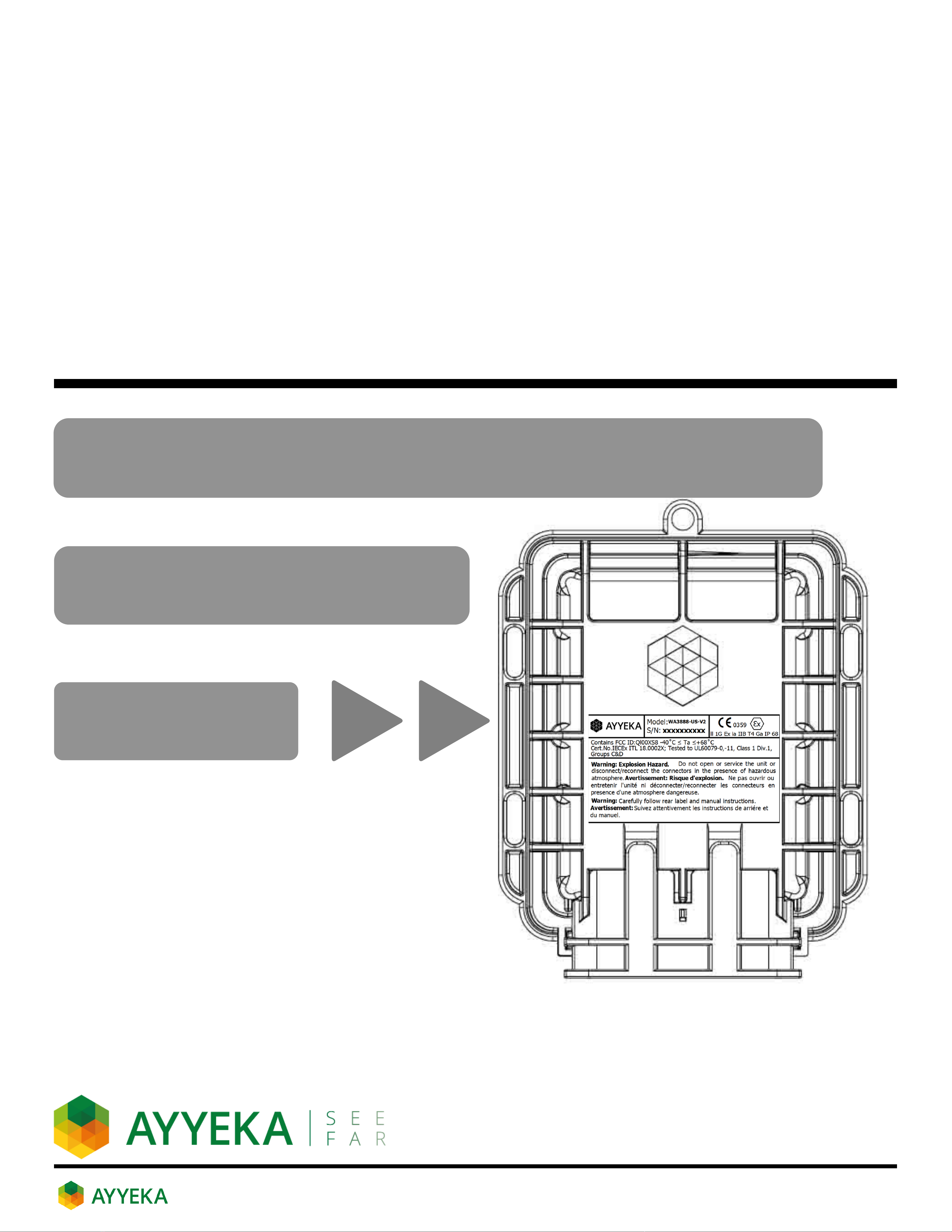
A polarized "Protector" guard, which is part of the Explosive Environ-
ment requirement, is installed over the unit's external connectors to
disable disconnection after the equipment is installed in the Explo-
sive Environment.
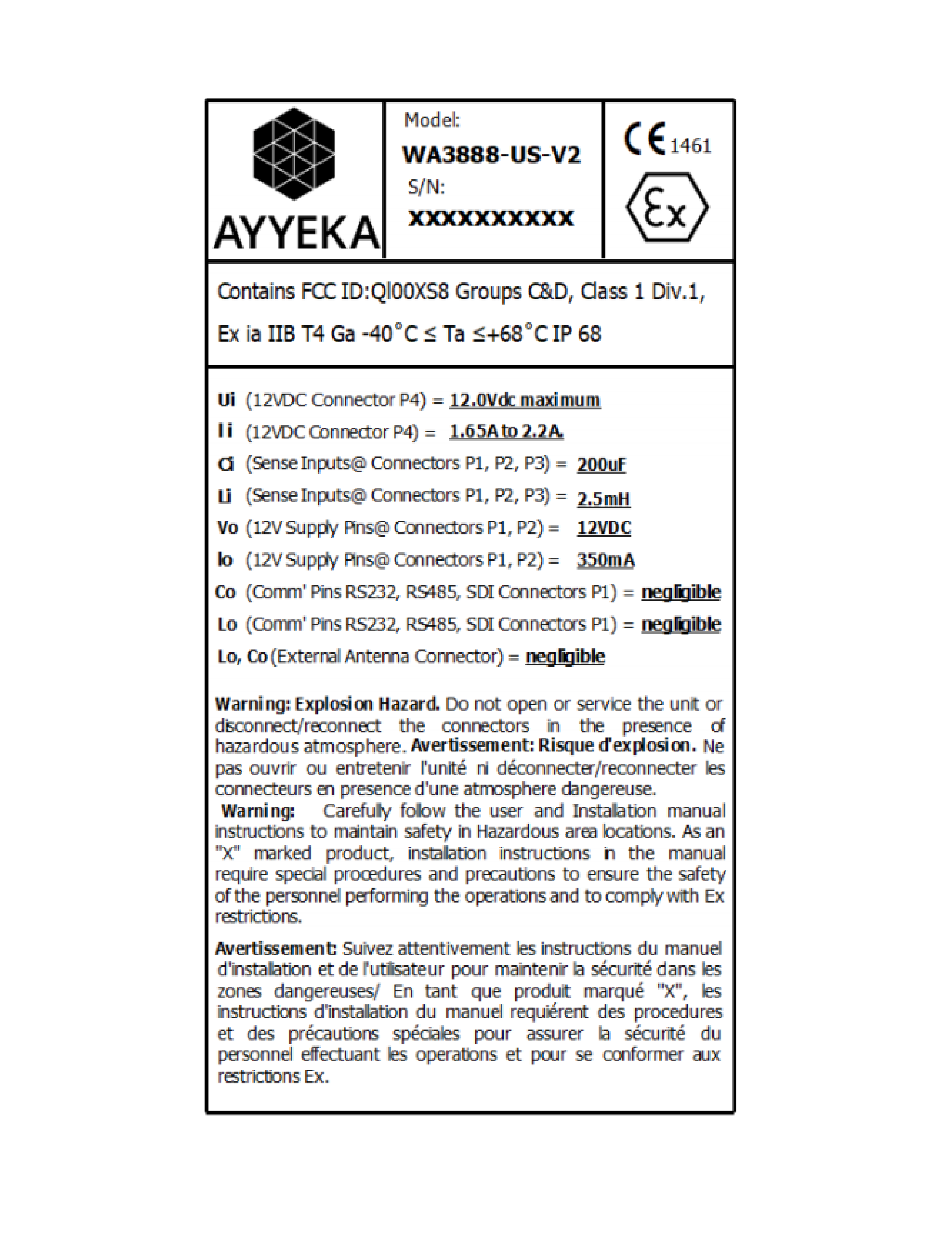
The following WARNING is to be marked on the equipment in a
visible area, and the Instruction Manual must include explanations
of these instructions:
Explosion Hazard. Do not open or service the unit or disconnect/
reconnect the connectors in the presence of hazardous atmos-
phere.
WARNING
8

INTRINSIC SAFETY
Intrinsic Safety (IS) is an approach to the design of electronic equipment
going into hazardous areas that ensures there are no conditions under
which the equipment can operate that could cause a release of energy
sufficient to ignite a hazardous gas vapor or dust mixture. Devices that
meet the low power, current-limited design criteria are deemed
Intrinsically Safe (IS).
The Wavelet has been certified and tested to worldwide IECEx
(International Electrotechnical Commission Explosive) standards. The
IECEx scheme allows demonstrated compliance for use in Zone 0
(equivalent to Class 1, Division 1 in North America) aeas in the following
countries:
United States India Slovenia Denmark
Germany Russia Croatia Netherlands
Poland Canada Korea Switzerland
Australia Italy South Africa Finland
Hungary Singapore Czech Republic New Zealand
Romania China Malaysia Turkey
Brazil Japan Sweden
9

CONTROL DRAWING
The control drawing Assembly No. 0100591 depicted below provides the
recommended electrical layout for the installation.
Use the equipment only as specified in this manual and according to the
intrinsic safety control drawing. Failure to do so may impair the protection
provided by the equipment.
10

Magnetic activator key
FRONT
BOTTOM
IP 68/ NEMA 6P Wavelet
Ex mechanical enclosure
Slots for zip ties and/or
bolts for mounting
Panel connectors
protector
Sensor port #3
Cellular antenna
port
Sensor port #2
External power
port
Sensor port #1
SCHEMATIC
13.3 cm
(5.2 in)
17.4 cm
(6.9 in)
7.3 cm
(2.8 in)
11

Military-grade, potted lithium
battery pack (field replaceable,
non-rechargeable)
Interface board ON/OFF switch
Indicator LEDs
GSM antenna
NOTE: Potted
GPS antenna
SIM card slot #1
SIM card slot #2
Memory card
Cellular modem
INTERNAL
UPPER ENCLOSURE
INTERNAL
LOWER ENCLOSURE
SCHEMATIC
12

Magnet Activator Key
Panel connectors protector and
and security screw
1x
1x
3x
M8 female field attachable
power connector
M12 8-pin female field
attachable
sensor connectors
(optional; ordered separately)
Wavelet Ex Device
COMPONENTS
13

Zip ties, screws, and anchors
2x 4x 4x
COMPONENTS
Cellular antenna and
mounting bracket
(REQUIRED and sold separately)
14

SENSOR CONNECTION
Connection of sensor(s) to the device must be done in an unclassi-
fied zone. Failure to perform this action in an unclassified zone may
cause dangerous conditions.
Connect the sensor cable(s) assembly with the field attachable
connector to the mating panel connector on the device. Turn the
adjustable stainless-steel end piece to secure the field attachable
connector to the device.
1
IMPORTANT: Use the DEVICE PINOUT sheet at the end of this Guide to
know which device port to plug the sensor into. All device ports look
identical, but their internal wiring is different. Consequently, the sensor
will not work if it is plugged into the wrong port.
CAUTION: Do not turn the black
plastic hood of the connector.
Turning the black hood may cause
the wires to disconnect, break,
and/or damage the connector pins.
WARNING
TURN HERE
DO NOT
TURN HERE
15

EXTERNAL ANTENNA CONNECTION
Connect the Cellular antenna to the antenna port (ANT1).
The antenna does not appear in the remaining depictions
in this guide, but it must remain connected after it is properly
secured to the appropriate panel connectors.
Place the magnetic Wavelet Activator on the embossed Wavelet logo on the
front of the Wavelet enclosure.
The Wavelet will initiate a 15-minute test mode of sampling and send a few
transmissions of data. The device will then return to its default configura-
tion.
Wavelet Activator 16
2

Place the magnetic device activator key on the embossed logo on the
front of the device enclosure. Device will initiate a 15-minute test
mode of high frequency sampling and transmission. The device will
then return to its default configuration.
DEVICE ACTIVATION
The device should first be tested in an unclassified zone.
Failure to perform this initial testing action in an unclassified zone
may cause dangerous conditions.
WARNING
3
17

DEVICE ACTIVATION
The LED light on the back cover of the device indicates the device status.
All LEDs are off
Not connected to network. The LED lights
do not blink when the device is sampling.
Note: Device may be powered down (power
switch is in the OFF position), in Hibernate
mode, or have insufficient battery strength.
Device is activated using the magnetic
activator key.
Attempting to connect to GSM network.
Transmission of data is in progress via GSM.
The LED will turn off when the transmission
is complete.
GSM communication error. The device
failed to transmit.
Green-Red-Blue-Red-
Green LEDs blink
sequentially 5x
Green LED is blinking
Green LED remains on
Green-Red LEDs blink 5x
Function Description
Access the user interface at https://home.ayyeka.com using your
credentials. Expect data to appear within 15 minutes after the test
mode is initiated.
4
18

DEVICE ACTIVATION
The screen display should resemble the following:
If the device transmits
properly, you have completed the
installation successfully and can
begin collecting and viewing your
data!
If data does not
transmit properly, change the
device installation location and
activate again.
If the problem persists, contact
the Ayyeka Support Team for
help:
+1 (310) 876-8040 (US)
+31-40-209-1001 (EMEA)
+972-2-624-3732 (IL)
19
This manual suits for next models
4
Table of contents