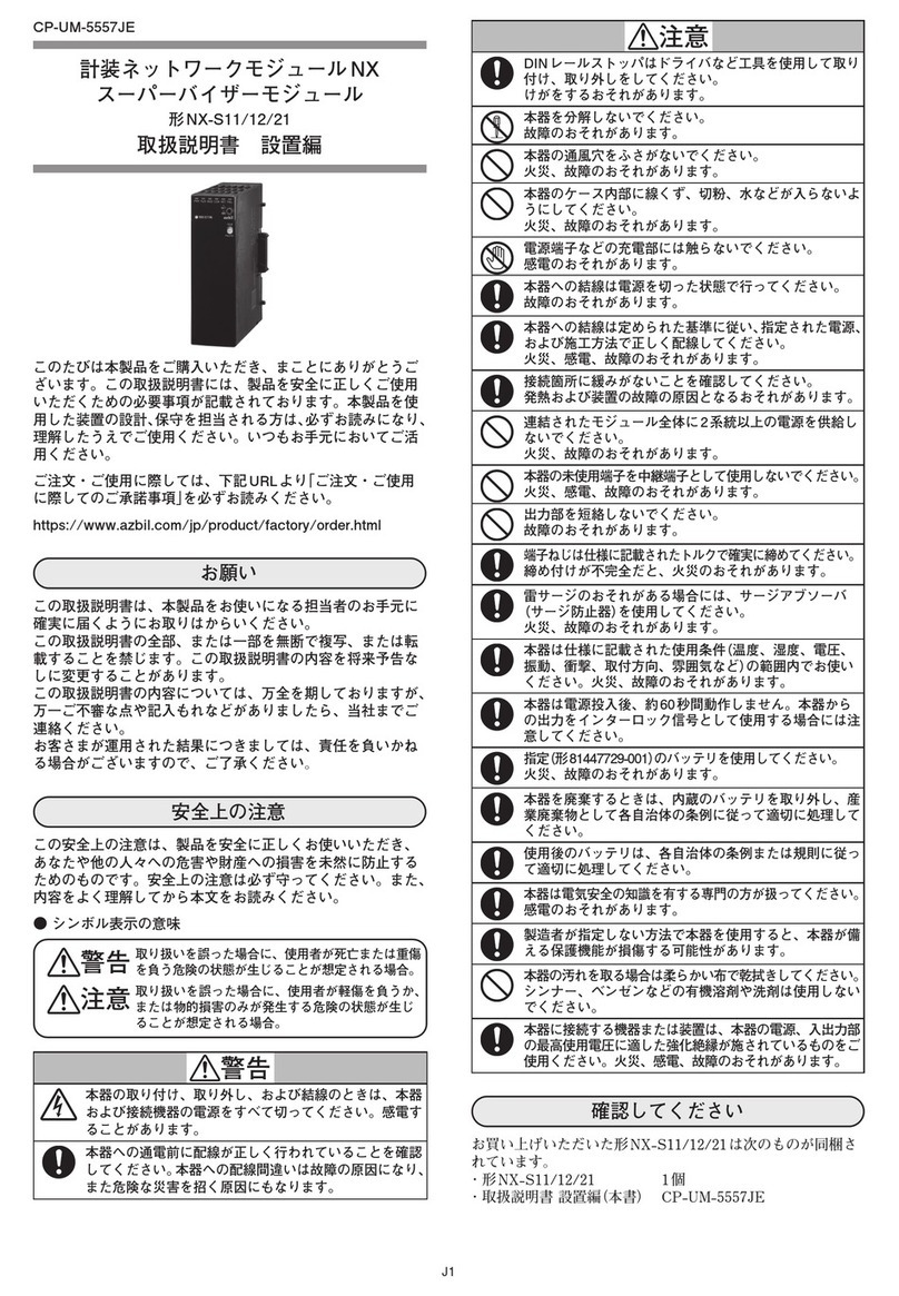
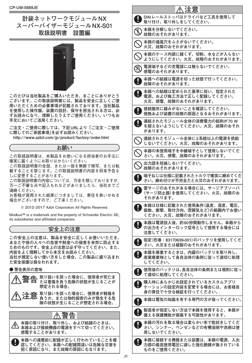
Azbil NX-CB2 User manual

J1
CP-UM-5715JE
計装ネットワークモジュール NX
コミュニケーションボックス NX-CB2
取扱説明書 設置編
このたびは当社製品をご購入いただき、まことにありがとうご
ざいます。この取扱説明書には、製品を安全に正しくご使用い
ただくための必要事項が記載されております。当社製品を使用
した操作盤、装置の設計、保守を担当される方は、必ずお読み
になり、理解したうえでご使用ください。いつもお手元におい
てご活用ください。
ご注文・ご使用に際しては、下記URLより「ご注文・ご使用に
際してのご承諾事項」を必ずお読みください。
http://www.azbil.com/jp/product/factory/order.html
お願い
この取扱説明書は、本製品をお使いになる担当者のお手元に確
実に届くようにお取りはからいください。
この取扱説明書の全部、または一部を無断で複写、または転載
することを禁じます。この取扱説明書の内容を将来予告なしに
変更することがあります。
この取扱説明書の内容については、万全を期しておりますが、
万一ご不審な点や記入もれなどがありましたら、当社までご連
絡ください。
お客様が運用された結果につきましては、責任を負いかねる場
合がございますので、ご了承ください。
© 2013–2017 Azbil Corporation All Rights Reserved.
安全上の注意
この安全上の注意は、製品を安全に正しくお使いいただき、あ
なたや他の人々への危害や財産への損害を未然に防止するため
のものです。安全上の注意は必ず守ってください。また、内容
をよく理解してから本文をお読みください。
当社が規定しない使い方をした場合、この製品に盛り込まれた
安全保護は損なわれます。
● 警告表示の意味
警告 取り扱いを誤った場合に、使用者が死亡ま
たは重傷を負う危険の状態が生じることが
想定される場合。
注意 取り扱いを誤った場合に、使用者が軽傷を
負うか、または物的損害のみが発生する危
険の状態が生じることが想定される場合。
警告
本器の取り付け、取り外し、および結線のときは、本器
および接続機器の電源をすべて切ってください。感電す
ることがあります。
本器への通電前に配線が正しく行われていることを確認
してください。本器への配線間違いは故障の原因になり、
また危険な災害を招く原因にもなります。
注意
DINレールストッパはドライバなど工具を使用して取り
付け、取り外しをしてください。
本器を分解しないでください。
故障のおそれがあります。
注意
本器の通風穴をふさがないでください。
火災、故障のおそれがあります。
本器のケース内部に線くず、切粉、水などが入らないよ
うにしてください。火災、故障のおそれがあります。
電源端子などの充電部には触らないでください。
感電のおそれがあります。
本器への結線はネットワークケーブルを除き電源を切った
状態で行ってください。故障のおそれがあります。
本器への結線は定められた基準に従い、指定された電源、
および施工方法で正しく配線してください。
火災、感電、故障のおそれがあります。
接続箇所に緩みがないことを確認してください。発熱お
よび装置の故障の原因となるおそれがあります。
連結されたモジュール全体の消費電力の総和が70 Wを超
えないようにしてください。火災、故障のおそれがあります。
連結されたモジュール全体に2系統以上の電源を供給しな
いでください。火災、故障のおそれがあります。
本器の未使用端子を中継端子として使用しないでくださ
い。火災、感電、故障のおそれがあります。
端子ねじは仕様に記載されたトルクで確実に締めてくださ
い。締め付けが不完全だと火災のおそれがあります。
雷サージのおそれがある場合には、サージアブソーバ
(サージ防止器)を使用してください。火災、故障のおそ
れがあります。
本器は仕様に記載された使用条件(温度、湿度、電圧、振動、
衝撃、取付方向、雰囲気など)の範囲内でお使いください。
火災、故障のおそれがあります。
本器を廃棄するときは、産業廃棄物として各自治体の条
例に従って適切に処理してください。
本器は電気の知識を有する専門の方が扱ってください。
製造者が指定しない方法で本器を使用すると、本器が備
える保護機能が損傷する可能性があります。
本器の汚れを取る場合は柔らかい布で乾拭きしてくださ
い。シンナー、ベンゼンなどの有機溶剤や洗剤は使用し
ないでください。
本器に接続する機器または装置は、本器の電源、入出力
部の最高使用電圧に適した強化絶縁が施されているもの
をご使用ください。
概 要
計装ネットワークモジュール NXは、イーサネットの標準採用に
より「分散計装」、「高速通信」、「省配線」、「省エンジニアリング」を
実現し、お客様に環境・品質・生産性向上という価値をご提供い
たします。
コミュニケーションボックス NX-CB2は、イーサネット同士を
接続するためのスイッチングハブです。
オプションで光ファイバーに接続する機種を選択できます。
形番構成
基本
形番 タイプ リング 接 続 ポ ート
数
オプ
ション
追加
処理 内容
1 2
NX- 計装ネットワークモジュール NX
CB2 4 ポートスイッチングハブ
(ステータス出力付き)
Nチェーン接続(サイドコネクタ)
ノンリング通信
Rチェーン接続(サイドコネクタ)リング通信
Nチェーン間接続(前面ポート)
ノンリング通信
Rチェーン間接続(前面ポート)リング通信
04 4ポート
0 RJ-45×4
1 RJ-45×3、2心LC×1
0 なし
D 検査成績書付き
T 熱帯処理品
K 硫化対策処理品
B 熱帯処理+検査成績書付き
L 硫化対策処理+検査成績書付き

J2
各部の名称
■ 本 体
メンテナンスジャック
(
メーカ ーメン テナンス 用 )
当社社内用です
スマートロ ーダパッケージ
SL P-NXには接 続できません
イーサネットポート1~4
L I N K /A C T 動 作 ランプ
イーサネットポート1~4
イー サネットケーブルを
接 続 す るポ ートで す
チェーン間接続は
イ ー サ ネ ッ ト ポ ー ト 3 、4
を使 用してくだ さ い
LED動作ランプ
PWR/RUN/MOD/
COM/NST/FAIL
イ ー サ ネ ッ ト ポ ー ト 3 、4
N S T 動 作ランプ
■ ベース
DIN
レールストッパ:
DINレールに
固定するときに
使用します
サイドコネクタ:
モジュールを連結する
ときに使用します
電 源 端 子:
1:DC24 V(+)
2:DC24 V(-)
ステータス 出 力 端 子 *:
4: DO2
チェーン間の接続先との
間が正常な場合にON
5: DOC
出 力コモン 端 子
6: DO1
チェーン間 接 続リング
通信が正常な場合にON
*NX-CB2 □ R だけ有効です
取り扱い上の注意
•
本器にはRS-485通信端子はありません。
取り付け
■ 取付場所
屋内に取り付けてください。図の数値は最低限必要な間隔
です。
50 mm
正面
50 mm
配 線 ダ クト な ど
配 線 ダ クト な ど
配 線 ダ クト な ど
NX
50 mm
配 線 ダ クト な ど
50 mm
配 線 ダ クト な ど
配 線 ダ クト な ど
50 mm
80 mm
50 mm NXNX
オプション 1 の場合、正面クリアランスは使用する光ファ
イバーケーブルの許容曲げ半径を考慮する必要があります。
次のようなところには取り付けないでください。
• 仕様の範囲を超えた高温、低温、高湿度、低湿度にな
るところ
• 硫化ガスなど腐食性ガスのあるところ
• 粉じん、油煙などのあるところ
• 直射日光、風雨が当たるところ
• 仕様の範囲を超えた機械的振動、衝撃のあるところ
• 高圧線の下、溶接機および電気的ノイズの発生源の近く
• ボイラなどの高圧点火装置から15m以内
• 電磁界の影響のあるところ
• 可燃性の液体や蒸気のあるところ
• 屋外
• 入出力のコモンモード電圧:対大地間の電圧が 30Vrms
以上、42.4Vピーク以上、DC60V以上のところ
■ モジュールの連結
本器はベース右のコネクタで別のモジュールと連結でき
ます。モジュールの連結はDINレールへ取り付ける前に
作業してください。連結することで、各モジュールの電源
および通信が接続され、配線を省くことができます。
■ 取付方法
本器はDINレールに取り付けて使用します。
DINレールを固定したあと、DINレールストッパを十分引
き出してからベースをレールに引っかけてください。
次にDINレールストッパを上方にカチッと音がするまで
押し込んでください。
取り扱い上の注意
•
本器は垂直な面にDINレールストッパを下側にして取り
付けてください。
■ 本体をベースに取り付ける
①本体下部のフックをベースに引っかけてください。
②本体上部のレバーがカチッと音がするまではめ込んで
ください。
①
フック
②レバー
取り扱い上の注意
•
同梱されているベースと本体の組み合わせは対にして使
用してください。
•
最初に本体下部のフックをベースに引っ掛けてくださ
い。フックが破損することがあります。
■ 本体をベースから取り外す
①本体を奥に向かって押さえつけてください。
②本体を押さえつけたまま本体上部のレバー先端を押し
てください。
③レバー先端を押したまま、本体を上部から手前に引き、
回転するように取り外してください。
①②③
取り扱い上の注意
• レバー先端を2 mm 以上押し込まないでください。レバーが折
れる可能性があります。
ここを押す〇
×この範囲は押さない

J3
結 線
■ 結線上の注意
• 配線については、内線規定、電気設備技術基準に従っ
て施工してください。
• 屋外配線はしないでください。落雷時破損することが
あります。
• 電源線の端末は絶縁被覆付きの圧着端子を使用してく
ださい。
• 結線は計器形番と端子番号を本体側面の配線図で確認
してから行ってください。
• 電源端子、ステータス出力端子の接続にはM3のねじに
適合する圧着端子を使ってください。
• 圧着端子などが隣の端子と接触しないように注意して
ください。
• 本器の信号線や電源線は、他の動力線や他の電源線か
ら60cm以上離してください。また、同一の配線管や
ダクト内を通さないでください。
• 他の計器と並列接続する場合は、他の計器の条件をよ
く調べてから計装してください。
• 本器は電源投入後、安定のため約3秒間は機能しない
ようになっています。
• 結線が終わったら、通電前に配線間違いのないことを
確認してください。
■ チェーン間接続(イーサネットポート3、4)
チェーン間接続をする場合は
イーサネットポート3、4に
接続してください。
■ 電源の接続
電源端子は次のように接続してください。
1 2
電源 DC24 V
4 5 6
+-
ULクラス2 電源を使用してください。
取り扱い上の注意
•
連結しているモジュール間は、電源が相互に接続されて
いるので、連結しているモジュールのどれか1つに電源
を供給してください。
•
電源は、連結しているモジュールの消費電力の総和を十
分にまかなえるものを選定してください。
•
電源に複数の配線をする場合、配線が困難な場合には中
継端子を設けるなどしてください。
■ ステータス出力の接続
チェーン間接続リング通信ステータス出力は次のように
接続してください。
DO2 DOC DO1
12
DC24V
+ -
4 5 6
電源 DC24 V
+/-または-/+
負荷 負荷
ステータス DO1 DO2
チェーン間接続でリング
通信が正常 ON ON
リング通信がどこかで異
常だが、自ノードと接続
先ノード間が正常
OFF ON
自ノードと近隣ノード間
に異常がある場合 OFF OFF
イーサネット
ポート3、4
取り扱い上の注意
•
RS-485通信ケーブルは接続しないでください。
•
NX-CB2□R だけ機能します。
■ ステータス出力回路
6DO1
4
5
DO2
DOC
■ 入出力間アイソレーション
実線は他のものとアイソレーションされていることを示
しています。
電源(サイドコネクタを含む)
*
ロジック回路
メンテナンスジャック
表示部(LED)
イーサネットポート1
イーサネットポート2
イーサネットポート3
イーサネットポート4
ステータス出力
サイドコネクタイーサネット通信*
* 電源、ステータス出力、サイドコネクタイーサネット通信は
絶縁関係を保持したままサイドコネクタに接続されています。
廃棄について
本器を廃棄するときは、各自治体の条例に従い、産業廃棄物
として適切に処理してください。
仕 様
■ 仕 様
● 基準条件
周囲温度 :23 ± 2℃
周囲湿度 :60 ± 5%RH(結露なきこと)
定格電源電圧 :DC24V
振 動 :0m/s2
衝 撃 :0m/s2
取付角度 :基準面± 3°
● 動作条件
周囲温度 :0 〜 50℃
(設置した状態での本器下面側にて)
周囲湿度 :10 〜 90%RH(結露なきこと)
動作許容電源電圧:DC21.6 〜 26.4V
振 動 :0 〜 3.2m/s2
(10 〜 150Hz XYZ各方向 2h)
衝 撃 :0 〜 9.8m/s2
取付角度 :基準面± 3°
じん埃 :0.3mg/m3以下
腐食性ガス :なきこと
高 度 :2000m 以下
汚染度(Pollutiondegree)
:2(通常のオフィス環境と同等)
● 輸送保管条件
周囲温度 :− 20 〜+ 70℃
周囲湿度 :5 〜 95%RH(結露なきこと)
振 動 :0 〜 9.8m/s2
(10 〜 150Hz XYZ各方向 2h)
衝 撃 :0 〜 300m/s2
(DINレール取付状態、上下方向 3 回)
包装落下試験 :落下高さ60cm
(1角 3 陵 6 面の自由落下法による)

J4
〔ご注意〕 この資料の記載内容は、お断りなく変更する場合もありますので
ご了承ください。 (26)
本 社 〒100-6419 東京都千代田区丸の内 2-7-3 東京ビル
北海道支店
東北支店
北関東支店
東京支社
中部支社
関西支社
中国支店
九州支社
☎(011)211 ー 1136
☎(022)290 ー 1400
☎(048)621 ー 5070
☎(03)6432 ー 5142
☎(052)324 ー 9772
☎(06)6881 ー 3383~ 4
☎(082)554 ー 0750
☎(093)285 ー 3530
〈COMPO CLUB〉 http://www.compoclub.com
〈アズビル株式会社〉 http://www.azbil.com/jp/
製品のお問い合わせは…
コール センター : 0466-20-2143
2013年 3月 初版発行(V)
2017 年 11 月 改訂 6版(F)
● ステータス出力端子
外部許容電源電圧:DC20.4 〜 27.6V(24V± 15%)
出力許容電流 :DC100mA 以下
OFF時リーク電流 :100 μA以下
NX-CB2□ R だけ使用できます。
● その他
絶縁抵抗 :DC500V、20MΩ以上(電源端子①②
と、電源端子と絶縁されたI/O端子間)
耐電圧 :AC500V、1min(電源端子①②と、電
源端子と絶縁されたI/O 端子間)
消費電力 :
4W以下(オプション 0 動作条件にて)
5W以下(オプション 1 動作条件にて)
電源投入時突入電流
:10A 以下(動作条件にて)
電源投入時の動作:リセット時間約3s(通常動作を行うま
での時間、基準条件にて)
ケース材質、色 :変性 PPO 樹脂、黒
取付方法 :DIN レール取り付け
端子ねじ適正締付トルク
:0.6 ± 0.1N·m
質 量 :300g 以下
適合規格 :CE(EN61326-1、Foruseinindustrial
locations)、cUL(UL61010-1)
● 通信仕様
ポート数 :4
伝送路形式 :•イーサネットポート1、2
IEEE802.3/IEEE802.3u10BASE-
T/100BASE-TX(オートネゴシエー
ション、AutoMDI/MDI-X機能あり)
•
イーサネットポート3、4(オプション 0)、
イーサネットポート3(オプション1)
IEEE802.3u100BASE-TX
(FullDuplex、AutoMDI/MDI-X機能
あり。コミュニケーションボックス間
を接続する場合以外は、接続する機器
はオートネゴシエーション機能が有効
であること)
•イーサネットポート4(オプション 1)
IEEE802.3u100BASE-FX
(FullDuplex、波長1300nm)
コネクタ :•100BASE-TXコネクタ RJ-45
•100BASE-FX コネクタ 2 心 LC
ケーブル :•100BASE-TXケーブル
UTPケーブル(4P)Cat5e 以上
(ストレート)(両端ANSI/TIA/EIA-
568B)最長 100m
•100BASE-FX ケーブル
マルチモード・グレーテッドインデッ
クスタイプ(屈折率分布型)
光ファイバーケーブルGI-50/125
またはGI-62.5/125(2 心)最長 2km
注 光ファイバーケーブルの取り扱いに
ついては光ファイバーメーカーの注
意事項をご覧ください
● コミュニケーションアダプタ
(別売 形番:NX-CL1□□□□□□、NX-CR1 □□□□□□)
ポート数 :1
伝送路形式 :IEEE802.3u100BASE-TX
(FullDuplex、AutoMDI/MDI-X機能
あり。接続する機器はオートネゴシ
エーション機能が有効であること)
コネクタ :RJ-45
ケーブル :UTP ケーブル(4P)
Cat5e以上(ストレート)
(両端ANSI/TIA/EIA-568-B)
NX-CB2の左側面にはコネクタがありません。
NX-CL1□□□□□□は連結できません。
● ターミナルアダプタ
(別売 形番:NX-TL1□□□□□□、NX-TR1 □□□□□□)
チェーン接続リング通信端(ベース内イーサネット通信
経路)として使用するためのアダプタです。
NX-CB2の左側面にはコネクタがありません。
NX-TL1□□□□□□は連結できません。
● コネクタキャップ(別売 形番 80700224-010)
サイドコネクタを保護するためのキャップです。
個数 :10
■ 外形寸法図
単位:mm
100
5
(10)
45 8
(20)
85
32.3

E1
CP-UM-5715JE
Network Instrumentation Module
NX-CB2 Communication Box
User’s Manual for Installation
Thank you for purchasing an Azbil Corporation product.
This manual contains information for ensuring the correct use of
this product.
This manual should be read by those who design and maintain
equipment that uses this product.
Be sure to keep this manual nearby for handy reference.
Please read “Terms and Conditions”from the following URL be-
fore ordering and use.
http://www.azbil.com/products/factory/order.html
NOTICE
Be sure that the user receives this manual before the product is used.
Copying or duplicating this user’s manual in part or in whole is
forbidden. The information and specifications in this manual are
subject to change without notice.
Considerable effort has been made to ensure that this manual is
free from inaccuracies and omissions. If you should find an error or
omission, please contact the azbil Group.
In no event is Azbil Corporation liable to anyone for any indirect,
special or consequential damages as a result of using this product.
© 2013–2017 Azbil Corporation All Rights Reserved.
SAFETY PRECAUTIONS
Safety precautions are for ensuring safe and correct use of this
product, and for preventing injury to the operator and other
people or damage to property. You must observe these safety
precautions. Also, be sure to read and understand the contents of
this user’s manual.
If this equipment is used in a manner not specified by the manu-
facturer, the built-in protection provided by the equipment will
be impaired.
zKey to symbols
WARNING
Warnings are indicated when mishandling this prod-
uct might result in death or serious injury to the user.
CAUTION
Cautions are indicated when mishandling this product
might result in minor injury to the user, or only physi-
cal damage to this product.
WARNING
Before removing, mounting, or wiring this device, be sure to turn off
the power to the device and any connected devices. Failure to do so
might cause electric shock.
Before starting transmission to the NX-CB1, be sure to verify that it
is wired properly. A wiring mistake can cause faulty operation or a
dangerous accident.
CAUTION
Use a tool such as a screwdriver to mount and remove the DIN rail
locking tab.
CAUTION
Do not disassemble the NX-CB2. Doing so might cause device failure.
Do not block ventilation holes. Doing so might cause fire or device
failure.
Do not allow wire clippings, metal shavings or water to enter the
controller case. They might cause fire or device failure.
Do not touch electrically charged parts such as the power terminals.
Doing so might cause electric shock.
Before wiring the NX-CB2 except network cables, be sure to turn the
power OFF. Failure to do so might cause device failure.
Wire the NX-CB2 properly using the specified types of wire and
following recognized installation methods. Failure to do so might
cause electric shock, fire or device failure.
Make sure that there are no loose connections. Failure to do so
might cause overheating or device failure.
Ensure the total power consumption of all linked modules does not
exceed 70 W. Failure to do so might cause fire or faulty operation.
Supply power to all linked modules from the same power source.
Using two or more power sources can cause fire or faulty operation.
Do not use unused terminals on the NX-CB2 as relay terminals.
Doing so might cause electric shock, fire or device failure.
Firmly tighten the terminal screws to the torque listed in the speci-
fications. Insufficient tightening of terminal screws might cause
electric shock or fire.
If there is a risk of a power surge caused by lightning, use a surge
absorber (surge protector). Failure to do so may cause fire or device
failure.
Use the NX-CB2 within the operating ranges recommended in the
specifications (temperature, humidity, voltage, vibration, shock,
mounting direction, atmosphere, etc.). Failure to do so might cause
fire or device failure.
When disposing of the NX-CB2, dispose of it appropriately as indus-
trial waste in accordance with local regulations.
The NX-CB2 should be handled by a specialist with expertise in elec-
trical circuits.
If the NX-CB2 is used in a manner not specified by the manufacturer,
the protection provided by the device may be impaired.
If the NX-CB2 is dirty, wipe it with a soft dry cloth. Never use an or-
ganic solvent like benzene or thinner.
Make sure that devices and equipment connected to the NX-CB2
have reinforced insulation suitable for the maximum operating volt-
age of its power supply, inputs, and outputs.
OVERVIEW
Linked by Ethernet, Network Instrumentation Modules make distributed
instrumentation, high-speed communications, and easy installation all
possible at the same time. The module also creates value for customers
by offering reduced environmental impact, superior product quality, and
higher productivity.
The NX-CB2 communication box is a switching hub that connects
Ethernet peer networks.
As an optional extra, models compatible with fiber-optic cable are
available.
MODEL SELECTION TABLE
Basic
model
No.
Type
Ring
connection
Ports Option Addition Specification
1 2
NX- Network Instrumentation Module
CB2 4-port switching hub (with status output)
NChain (side connector) non-ring connection
communications
RChain (side connector) ring connection
communications
NInter-chain (front port) non-ring connection
communications
RInter-chain (front port) ring connection
communications
04 4 ports
0 RJ-45×4
1 RJ-45×3, 2-core LC×1
0 None
D With inspection report
T Tropicalization treatment
K Anti-sulfuration treatment
B Tropicalization treatment + inspection report
L Anti-sulfuration treatment + inspection report

E2
NAMES OF PARTS
Body
LED operation indicators
PWR/RUN/MOD/
COM/NST/FAIL LINK/ACT indicator for
Ethernet ports 1 to 4
Ethernet ports 1 to 4:
Used for connecting an
Ethernet cable.
Use Ethernet ports 3 and 4
for a connection between
two chains.
Maintenance jack
(for Azbil Corporation use only):
Cannot be connected to
SLP-NX smart loader
package.
NST indicator for
Ethernet ports 3 and 4
Base
Power supply terminal:
1: 24 V DC (+)
2: 24 V DC (−)
Side connector:
Used for connecting modules.
Status output terminals*:
DIN rail locking tab:
Used for locking on a DIN rail.
4: DO2
In a connection
between chains,
output to adjoining
modules is ON if
status is normal.
5: DOC
Output common
terminal
6: DO1
In a ring communi-
cation connection
between chains,
output is ON when
status normal.
*Operative on NX-CB2_R only.
Handling Precautions
• The NX-CB2 has no RS-485 terminal.
INSTALLATION
Installation location
Install modules indoors. Numbers in the figure are minimum
clearances.
Wiring duct, etc.
NX NX
50 mm
Wiring duct, etc.
50 mm50 mm
Wiring duct, etc.
80 mm
From the front
Wiring duct, etc.
50 mm 50 mm
50 mm
Wiring duct, etc.
Wiring duct, etc.
In the case of option 1, when determining clearance for the front
panel, be sure to take the minimum bend radius of the fiber optic
cable into account.
Install the controller in a location that meets the following criteria:
• No high/low temperature/humidity.
• Free from sulfide gas or corrosive gas.
• Not dusty or sooty.
• Protected from direct sunlight, wind, and rain.
• Little mechanical vibration or shock.
• Not close to high voltage line, welding machine or other elec-
trical noise generating source.
• At least 15meters away from the high voltage ignition device
for a boiler.
• No strong magnetic fields.
• No flammable liquid or gas.
• Indoors
• I/O common mode voltages: voltage to ground is 30Vrms
min., 42.4V peak min., and 60VDC min.
Linking modules
The NX-CB2 can be linked to other modules using the connector
on the right of the base. Modules must be linked before the NX-
CB2 is mounted on the DIN rail. When linked, modules share the
power supply and RS-485 connection, eliminating the need for
wiring.
Mounting procedure
The NX-CB2 is used while mounted on a DIN rail.
After mounting the DIN rail and pulling the locking tab com-
pletely off, hook the base onto the DIN rail. Then, push the DIN
rail locking tab upwards firmly until it clicks into place.
Handling Precautions
• Mount the module on a vertical surface with the DIN locking
tab facing downward.
Attaching the body to the base
(1) Fit the hook on the main unit into the base.
(2) Push the main unit onto the base until the lever clicks.
(1)
Hook
(2) Lever
Handling Precautions
• The included base and main unit must be used as a pair.
• Be sure to fit the hook on the main unit into the base first. If
this is not done, the hook might be broken during mounting.
Removing the main unit from the base
(1) Grasp the main unit near the front and push it in toward the
base.
(2) While pushing, press the tip of the lever on the top of the
main unit.
(3) While pressing the tip of the lever, rotate the main unit down
to remove it.
(1) (2) (3)
Handling Precautions
• Press the tip of the lever. Do not press it down excessively
(2mm or more). Doing so may break the lever.
Press here.
Do not press in this area.

E3
WIRING
Wiring Precautions
• All wiring must comply with applicable codes and ordinances.
• Do not run wires outside. The equipment could be damaged in
the event of lightning.
• When connecting wires to the power terminals, use crimp ter-
minals with insulating sleeves.
• Before wiring, check the model number and terminal numbers
with the circuit drawing on the side of the device.
• For connections to power and the status output terminals, use
crimp terminals that are the correct size for M3 screws.
• Be careful not to allow any crimp-type terminal lugs to touch
adjacent terminals.
• The signal wires and power wires of the module should be at
least 60cm away from other power wires or power sources.
Also, do not pass these wires through the same conduit or wir-
ing duct.
• Before connecting the NX-CB2 to other devices in parallel,
check their connection conditions carefully.
• To ensure stable operation, the NX-CB2 is designed not to op-
erate for three seconds after the power is turned ON.
• After wiring, check that there are no mistakes before turning
the power ON.
Connection between chains (Ethernet ports 3
and 4)
Use Ethernet ports 3 and 4 for a
connection between chains.
Connecting the power supply
Connect the power terminals as shown below.
12
Instrument power supply 24 V DC
4 5 6
+ −
The power supply unit must be a UL Class 2 power supply unit.
Handling Precautions
• Since linked modules supply power to each other, supply
power to only one of a group of linked modules.
• Use a power supply that can supply the total power
requirement of the linked modules.
• If there are multiple wires to the power supply and wiring is
difficult, add a relay terminal or the like.
Wiring for status outputs
Connect the status outputs for a ring communication connection
between chains as follows.
DO2 DOC DO1
12
24 V DC
+−
4 5 6
+/− or −/+
Load Load
Power supply
(24 V DC)
Status DO1 DO2
Ring communication is normal
for a connection between
chains.
ON ON
There is a problem somewhere
with ring communication, but
this node's connections to
adjacent nodes are normal.
OFF ON
There is a problem with the
connection between this node
and a neighboring node.
OFF OFF
Ethernet
port 3, 4
Handling Precautions
• Do not connect an RS-485 cable.
• This function available on the NX-CB2_R only.
Status output circuit
DO1
Logic circuit
DO2
DOC
6
4
5
I/O isolation
Items surrounded by solid lines are isolated from other signals.
Power supply (including side connector)*
Logic circuits
Maintenance jack
Displays (LED)
Ethernet port 1
Ethernet port 2
Ethernet port 3
Ethernet port 4
Status output
Ethernet communications through side connector*
* Power, status output, and side-connector Ethernet communications
are isolated from each other.
DISPOSAL
When discarding the NX-CB2, dispose of it as industrial waste, fol-
lowing local regulations.
SPECIFICATIONS
Specifications
zStandard conditions
Ambient temperature: 23 ±2°C
Ambient humidity: 60 ±5%RH (without condensation)
Rated power voltage: 24VDC
Vibration resistance: 0m/s2
Shock resistance: 0m/s2
Mounting angle: Reference plane ±3°
zOperating conditions
Ambient temperature: 0 to 50°C (below the installed module)
Ambient humidity: 10 to 90%RH (without condensation)
Allowable power supply voltage for operation:
21.6 to 26.4VDC
Vibration resistance: 0 to 3.2 m/s2(10 to 150Hz for 2h each in X,
Y, and Z directions)
Shock resistance: 0 to 9.8 m/s2
Mounting angle: Reference plane ±3°
Dust: 0.3 mg/m3max.
Corrosive gas: None
Altitude: 2000m max.
Pollution degree: 2 (equivalent to normal office environments)
zTransportation conditions
Ambient temperature: −20 to +70°C
Ambient humidity: 5 to 95%RH (without condensation)
Vibration resistance: 0 to 9.8 m/s2(10 to 150Hz for 2h each in X,
Y, and Z directions)
Shock resistance: 0 to 300 m/s2(vertically shaken three times
while mounted on DIN rail)
Package drop test: Drop height 60cm (free fall on 1 corner, 3
sides, 6 planes)

E4
1-12-2 Kawana, Fujisawa
Kanagawa 251-8522 Japan
URL
: http://www.azbil.com
(09)
Specifications are subject to change without notice.
1st edition: Mar. 2013 (V)
6th edition: Nov. 2017 (F)
zStatus output terminal
External power source allowable voltage:
20.4 to 27.6V DC (24V ±15%)
Allowable output current:
100mA DC max.
OFF-state leakage current:
100μA max. Available on NX-CB2_R only.
zOther specifications
Insulation resistance: 500V DC, 20MΩ min. (between power
supply terminal and I/O terminals insulated
from the power supply terminal 1, 2)
Dielectric strength: 500V AC, 1min (between power supply ter-
minal and I/O terminals insulated from the
power supply terminal 1, 2)
Power consumption: 4W max. (option 0 under operating condi-
tions), 5W max. (option 1 under operating
conditions)
Power ON inrush current:
10A max. (under operating conditions)
Power ON behavior: Requires approx. 3s before normal operation
begins (under standard conditions)
Case material/color: Modified PPO resin, black
Mounting procedure: DIN rail
Terminal screw tightening torque:
0.6 ±0.1N·m
Mass: 300g max.
Standards compliance:
CE (EN61326-1, For use in industrial loca-
tions), cUL (UL61010-1)
zCommunication specifications
Ports: 4
Communication path type:
• Ethernet port 1 and 2
IEEE 802.3/IEEE 802.3u 10BASE-T/
100BASE-TX (with Auto Negotiation and
Auto MDI/MDI-X functions)
• Ethernet ports 3 and 4 (option 0), Ethernet
port 3 (option 1)
IEEE802.3u 100BASE-TX (full duplex,
with auto-MDI/MDI-X. The auto-negotia-
tion function on a connected device should
be enabled except when the device is con-
nected between communication boxes.)
• Ethernet port 4 (option 1)
IEEE802.3u 100BASE-FX (full duplex,
wavelength 1300nm)
Connector: • 100BASE-TX connector: RJ-45
• 100BASE-FX connector: 2-core LC
Cable: • 100BASE-TX cable
UTP cable (4P), Cat 5e min. (straight)
(both ends, ANSI/TIA/EIA-568-B), 100 m
max.
• 100BASE-FX cable
Multi-mode graded index optical fiber, GI-
50/125 or GI-62.5/125 (2-cores), 2km max.
Note: For handling of optical fiber, see the
manufacturer’s instructions.
zCommunication adaptor (sold separately, model Nos. NX-
CL1_ _ _ _ _ _ , NX-CR1_ _ _ _ _ _ )
No. of ports: 1
Communication path type:
IEEE 802.3u 100BASE-TX (with full duplex
and Auto MDI/MDI-X functions. The auto-
negotiation function on a connected device
should be enabled.)
Connector : RJ-45
Cable : UTP cable (4P) Cat 5e min. (straight) (both
ends, ANSI/TIA/EIA-568-B)
NX-CB2 cannot be connected with NX-CL1_ _ _ _ _ _, because
there is no connector on a left side of NX-CB2.
zTerminal adaptor (sold separately, model Nos.
NX-TL1_ _ _ _ _ _ , NX-TR1_ _ _ _ _ _ )
An adaptor used as a chain connection ring communications
terminal (Ethernet path in the base)
NX-CB2 cannot be connected with NX-TL1_ _ _ _ _ _, because
there is no connector on a left side of NX-CB2.
zConnector cap (sold separately, model No.80700224-010)
Used to protect the side connectors.
Quantity: 10
External Dimensions Unit: mm
100
5
(10)
45 8
(20)
85
32.3
CP-UM-5715JE-1
Table of contents
Other Azbil Network Hardware manuals