3
AB-7484-U
Safety Precautions
Please read instructions carefully and use the
product as specified in this manual. Be sure to keep
this manual nearby for quick reference.
Restrictions on Use
This product was developed, designed, and
manufactured for general air conditioning use.
Do not use the product in a situation where human
life may be at risk or for nuclear applications in
radiation controlled areas. If you wish to use the
product in a radiation controlled area, please
contact Azbil Corporation.
Particularly when the product is used in the
following applications where safety is required,
implementation of fail-safe design, redundant
design, regular maintenance, etc., should be
considered in order to use the product safely and
reliably.
• Safety devices for protecting the human body
• Start/stop control devices for transportation
machines
• Aeronautical/aerospace machines
For system design, application design, instructions
for use, or product applications, please contact
Azbil Corporation.
Azbil Corporation bears no responsibility for any
result, or lack of result, deriving from the
customer’s use of the product.
Recommended Design Life
It is recommended that this product be used within
the recommended design life.
The recommended design life is the period during
which you can use the product safely and reliably
based on the design specifications.
If the product is used beyond this period, its failure
ratio may increase due to time-related
deterioration of parts, etc.
The recommended design life during which the
product can operate reliably with the lowest failure
ratio and least deterioration over time is estimated
scientifically based on acceleration tests,
endurance tests, etc., taking into consideration the
operating environment, conditions, and frequency
of use as basic parameters.
The recommended design life of this product is 10
years.
The recommended design life assumes that
maintenance, such as replacement of the limited
life parts, is carried out properly.
Refer to the section on maintenance in this manual.
Warnings and Cautions
WARNING
Alerts users that improper handling
may cause death or serious injury.
CAUTION
Alerts users that improper handling
may cause minor injury or material
loss.
Signs
Notifies users that specific actions are
prohibited to prevent possible danger. The
symbol inside graphically indicates the
prohibited action. (For example, the sign on
the left means that disassembly is
prohibited.)
Instructs users to carry out a specific
obligatory action to prevent possible danger.
The symbol inside graphically indicates the
actual action to be carried out. (For example,
the sign on the left indicates general
instructions.)
CAUTION
Do not freeze this product.
Doing so may damage the valve body and
cause leakage.
When piping this product, be sure there is no
foreign matter in the pipes.
If foreign matter remains in the pipes, the
product may break down.
Install and use this product under the
conditions specified by this manual.
Failure to do so may cause device failure.
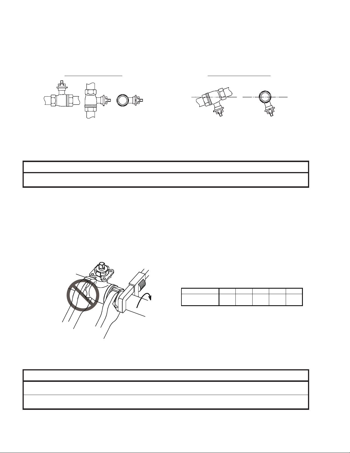
Do not screw a pipe excessively far into this
product.
Doing so may damage the inside of the valve
and cause leakage outside of the valve, or
may cause malfunction.
After installation, make sure no fluid leaks
from the valve-pipe connections.
Improper piping may cause fluid leakage
outside of the valve.
Do not put a load or weight on this product.
Doing so may damage the product.
Do not carelessly touch this product when it is
used to control hot water.
Doing so may result in burns, because the
product reaches a high temperature.