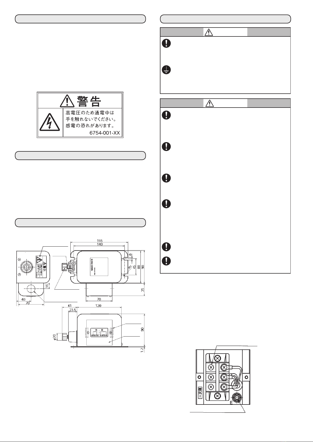
Azbil ATN110A-1 User manual

E1
CP-SP-1340E
ATN110A-1
IGNITION TRANSFORMER
User’s Manual
Thank you for purchasing an Azbil Corporation product.
This manual contains information for ensuring correct use of
the this product. It also provides necessary information for in-
stallation, maintenance, and troubleshooting.
This manual should be read by those who design and maintain
devices that use the this product.
Be sure to keep this manual nearby for handy reference.
Please read the“Terms and Conditions”from the following URL
before ordering or use:
http://www.azbil.com/products/bi/order.html
NOTICE
Be sure that the user receives this manual before the product
is used.
Copying or duplicating this user’s manual in part or in whole is
forbidden. The information and specifications in this manual are
subject to change without notice.
Considerable effort has been made to ensure that this manual is
free from inaccuracies and omissions. If you should find an error
or omission, please contact the azbil Group.
In no event is Azbil Corporation liable to anyone for any indi-
rect, special or consequential damages as a result of using this
product.
© 2011-2013 Azbil Corporation All Rights Reserved.
SAFETY PRECAUTIONS
Safety precautions are for ensuring safe and correct use of this
product, and for preventing injury to the operator and other
people or damage to property. You must observe these safety
precautions. Also, be sure to read and understand the contents
of this user’s manual.
WARNING
Warnings are indicated when mishandling this prod-
uct might result in death or serious injury to the user.
CAUTION
Cautions are indicated when mishandling this prod-
uct might result in minor injury to the user, or only
physical damage to this product.
WARNING
High-voltage currents run through the secondary-side
terminals. Never touch them while the circuit is ener-
gized. There is a risk of electric shock.
Before removing, mounting, or wiring the
ATN110A-1, be sure to turn off the power to the
ATN110A-1 and all connected devices. Failure to do
so might cause electric shock.
Connect the ground terminal to a D-class ground
(resistance of 100 Ω or less) or better. Electric noise
may infrequently occur, adversely influencing other
equipment, or an electrical leak may occur, creating
an electric shock hazard.
CAUTION
Adjust the gap between the discharge electrodes and
also the air velocity between the electrodes so that
they are within the recommended values. Exceeding
the recommended values will raise the secondary
voltage, possibly burning out the transformer.
On the secondary side of this transformer, use the
specified type of wire with a length of no more than
1.5m. A wire exceeding this length on the secondary
side will raise the internal temperature of the ignition
transformer, possibly causing it to malfunction.
Keep the wiring for this transformer separate from
other wiring and piping. Contact or mixing of the
wiring of this transformer with other wiring may gen-
erate inductive noise, causing other equipment to
malfunction.
Only an experienced specialist who has knowledge
and expertise regarding combustion equipment and
combustion safety equipment should install, wire, in-
spect, adjust, and service this transformer.
Periodically clean the secondary-side insulators of
this transformer and the insulators of the spark rods
to keep them clean. Accumulation of soot or dust, or
condensation of moisture, may prevent normal dis-
charge, resulting in ignition failure of the burner.

E2
UNPACKING
When you unpack the product package, check that you have all the
items listed below. In the unlikely event that there is a problem, re-
port it immediately to your dealer.
■Accessories
•Grommets for conduit (2)
•Instruction manual (this booklet)
■Label
Affixed to the transformer
OVERVIEW
■Feature
•A transformer used for ignition of gas burners. Changing the
position of the internal lead on the primary side makes this
transformer compatible with either 100Vac or 200Vac.
•Wiring terminals are provided on both the primary and second-
ary sides.
•A drip-proof case is available.
EXTERNAL DIMENSIONS
unit : mm
2-22Φ Knock-Out Holes
Grommet (2)
Terminal
Cover
(accessory)
Secondary Side
Terminal, M5
WARNING :
RISK OF
ELECTRIC SHOCK
Plain Washers
M5 (2)
MOUNTING/WIRING
WARNING
Before removing, mounting, or wiring the
ATN110A-1, be sure to turn off the power to the
ATN110A-1 and all connected devices. Failure to do
so might cause electric shock.
Connect the ground terminal to a D-class ground
(resistance of 100 Ω or less) or better. Electric noise
may infrequently occur, adversely influencing other
equipment, or an electrical leak may occur, creating
an electric shock hazard.
CAUTION
On the secondary side of this transformer, use the
specified type of wire with a length of no more than
1.5 m. A wire exceeding this length on the secondary
side will raise the internal temperature of the ignition
transformer, possibly causing it to malfunction.
Keep the wiring for this transformer separate from
other wiring and piping. Contact or mixing of the
wiring of this transformer with other wiring may gen-
erate inductive noise, causing other equipment to
malfunction.
Only an experienced specialist who has knowledge
and expertise regarding combustion equipment and
combustion safety equipment should install, wire, in-
spect, adjust, and service this transformer.
Be sure to install this transformer in close contact
with the mounting plate, and be sure that the ground
terminal of this transformer is connected electrically
to other equipment. If this transformer is not firmly
attached to the mounting plate, high-frequency
noise will be generated, causing other equipment to
malfunction.
Connect wiring in accordance with the provided spec-
ifications and criteria.
Connect the power source to the equipment as the
last step. Otherwise there is a risk of electric shock or
equipment damage.
■Mounting
●Standard installation direction
Install this transformer with the label facing upward.
●Connection of the ground terminal
Make a good electrical connection between the ground termi-
nal of this transformer and the combustion equipment.
Primary Side Terminal, M4
Ground Terminal, M5×20
DETAIL : TERMINAL BOX
(with terminal cover removed)
Wiring when shipped from factory (for 200 V) Refer to note 1.

E3
■Wiring
•The primary-side wiring of this transformer is factory-con-
figured for use at 200Vac. To use this transformer at 100Vac,
reconnect the wiring as shown in the figure below.
AC100 V
Primary Side
Terminal
Primary Side
Terminal Secondary Side
Terminal
Secondary Side
Terminal
Lead Wire (Red)
(Black)
(Yellow)
Lead Wire (Red)
(Black)
(Yellow)
(Blue)
(Blue)
100 V 6000 V
Ground
AC200 V (when shipped from factory)
200 V 6000 V
Ground
•The use of a high-voltage cable made for neon tubes or automo-
biles (JIS C 3405) is recommended. If there is a problem with
radio noise, use a cable designed for noise prevention.
ADJUSTMENT
CAUTION
Adjust the gap between the discharge electrodes and
also the air velocity between the electrodes so that
they are within the recommended values. Exceeding
the recommended values will raise the secondary
voltage, possibly burning out the transformer.
■Points to check before use
•Check that this transformer is compatible with the supply
voltage.
•Check that this transformer’s discharge gap is the recommended
value of 2mm and that the air velocity between the electrodes is
the recommended value of 5 m/s or less. Note particularly that
an appropriate discharge cannot be obtained if the gap is either
too small or too large.
MAINTENANCE/INSPECTION
CAUTION
On the secondary side of this transformer, use the
specified type of wire with a length of no more than
1.5 m. A wire exceeding this length on the secondary
side will raise the internal temperature of the ignition
transformer, possibly causing it to malfunction.
Only an experienced specialist who has knowledge
and expertise regarding combustion equipment and
combustion safety equipment should install, wire,
inspect, adjust, and service this transformer.
■Periodic inspection
Periodic maintenance, including cleaning and replacement, is re-
quired to maintain normal sparking.
•Check that the gap and air velocity between the electrodes of
the spark rod of this transformer are the recommended values.
Sparking causes the gap between the electrodes to grow gradu-
ally larger.
•Check that the wiring connections are not loose.
•Clean the spark rod. If there is soot or the like on its tip, the
spark rod may fail to spark.
•Clean the transformer, insulators, etc., to prevent carbon
tracking.
•Check secondary high-voltage cables for deterioration.
Insulation breakdown may be caused by moisture (hydrolysis)
and other factors.

E4
1-12-2 Kawana, Fujisawa
Kanagawa 251-8522 Japan
URL
: http://www.azbil.com
(09)
Specications are subject to change without notice.
1st edition: Feb. 2011 (V)
3rd edition: Dec. 2013 (F)
SPECIFICATIONS
Primary-
pressure
Rated power supply
voltage
100/200Vac, 50–60Hz
(selectable by wiring change)
Allowable voltage 85 to 110% of rated voltage
Secondary-
pressure
Rated power supply
voltage
6000V
Allowable voltage
difference
6000V ±10%
(when secondary is open)
Short-circuit current 21mA at 50Hz, 16mA at 60Hz
Grounding system One-end grounding
Power consumption 155VA at 50Hz, 120VA at 60Hz
Operating time rating 50% duty (cycle of max. 60min pow-
ered up, 60min power off)
Recommended discharge gap 2mm
Recommended air velocity be-
tween electrodes
5m/s max.
Secondary high voltage cable
length
1.5m max.
Insulation resistance 50MΩ or more between the primary
winding and ground terminal with a
500Vdc megger
Dielectric strength 1500Vac for 1min or 1800Vac for 1s
between the primary winding and
ground terminal.
Induced voltage strength With the secondary open, 1.5times
the rated voltage of 100 or 200Vac for
1min on the primary side
Ambient temperature −20 to +55°C *
Ambient humidity 95%RH max.
Color Black, semigloss
Mass Approx. 3.45kg
Installation Four u-shaped notches for M6 screws
Accessories Two grommets for conduit
*If the transformer is continuously energized for 60minutes or longer, the
maximum allowable ambient temperature is 40°C.