Unit Type: Interface Board Version:
Unit Serial No.: Over Voltage Version:
Delivery Date: Circuit Breaker:
Installation Date: OPTO Relay:
Voltage: Oxygen Valve:
Mother Board Version: Drain Valve:
PLC Board Version: Vacuum Valve:
Driver Board Version: Internal Pump Type:
In addition to normal safety rules which should be observed with stationary
Ozone Generators and equipment, the following safety directions and pre-
cautions are of special importance.
When operating this unit, the operator must employ safe working practices
and observe all related local work safety requirements and ordinances.
The owner is responsible for maintaining the unit in a safe operating condi-
tion. Parts and accessories shall be replaced if unsuitable for safe operation.
Installation, operation, maintenance and repair shall only be performed by
authorized, trained, and competent personnel.
Normal ratings, pressures, temperatures, time settings, etc., Shall be dili-
gently adhered to.
Any modifi cation to the Ozone Generator, and/or related equipment, shall
only be performed in agreement with Azco Industries Limited and under
supervision of authorized, competent personnel.
If any statement in this book, especially with regard to safety, does not
comply with local legislation, the stricter of the two shall apply.
These precautions are general and cover several machine types and
equipment; hence some statements may not apply to the unit(s) de-
scribed in this book.
INSTALLATION
1. The Ozone equipment should only be lifted with adequate equipment in
conformity with local safety rules. Wear a safety helmet when working in
the area of overhead or lifting equipment.
2. Place the unit where the ambient air is as cool and clean as possible. If
necessary, install a suction duct. Never obstruct the air inlets. Care should
be taken to minimize the entry of moisture into the air inlet.
3. The unit shall be installed in such a way that an adequate fl ow of cooling air
is available.
4. Ensure that the rear exhaust vents are not in contact with or near to fl am-
mable materials.
5. All Azco products are designed to operate under vacuum. DO NOT operate
under pressure.
6. Install the equipment on a solid fl oor suitable for the weight, this applies to
all other equipment as well e.g. SPT’s and Foam Fractionator’s. If ground
is not level or can be subject to variable inclination, consult Azco Industries
Limited.
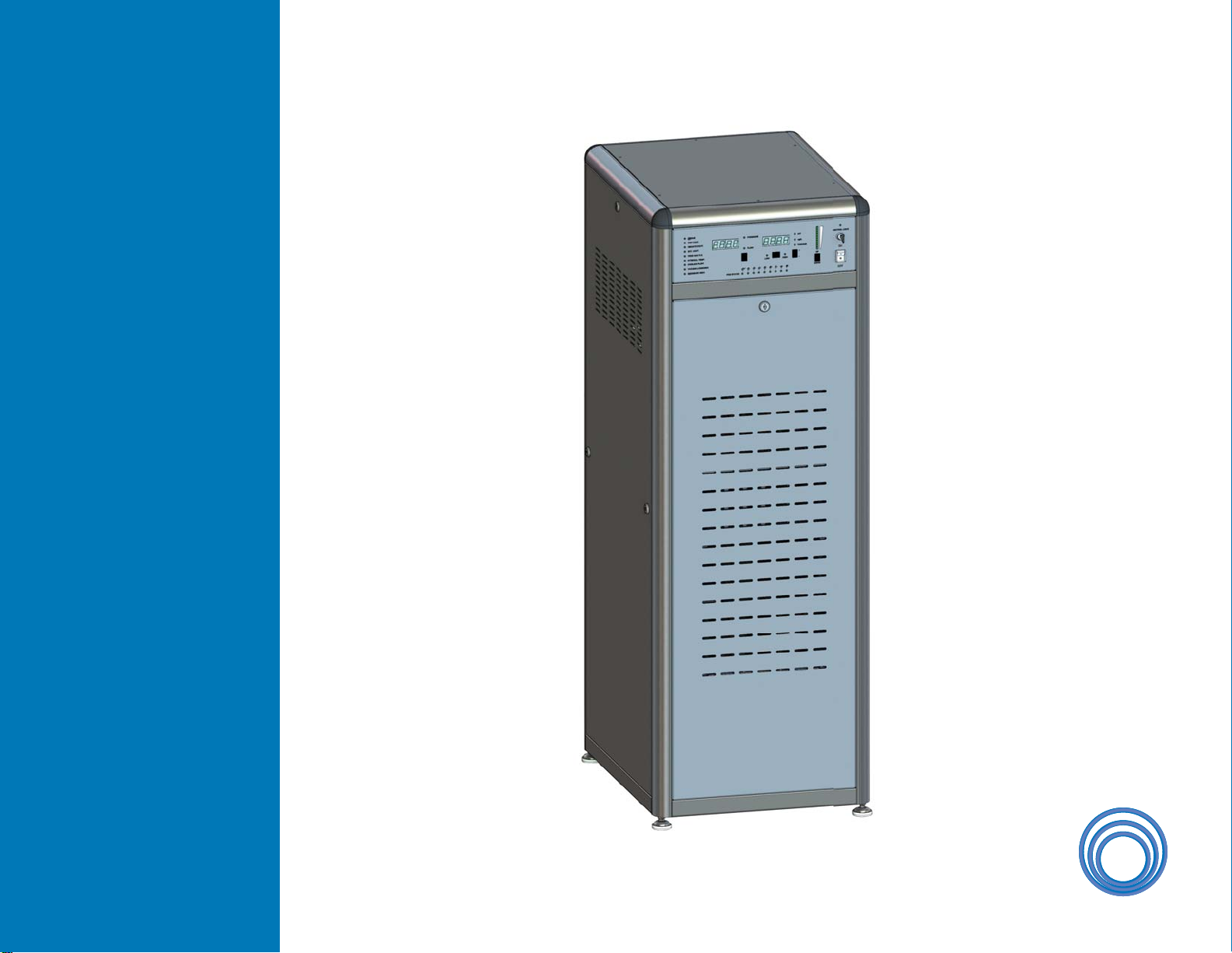
RM900
OWNERSHIP DATA
SAFETY PRECAUTIONS