IQ Switch R
ProxFusion R
Series
The number of available inductive sensor channels that can be used depends on the inductive sensing
mode used. Table 2 shows the available channels for the different sensor modes.
Table 2: IQS269A sensors capabilities for biased configuration
Sensing Mode Available
Channels
Number of
CTx pins
Number of
CRx pins
Bias pin
(CX1)
Total pins
required
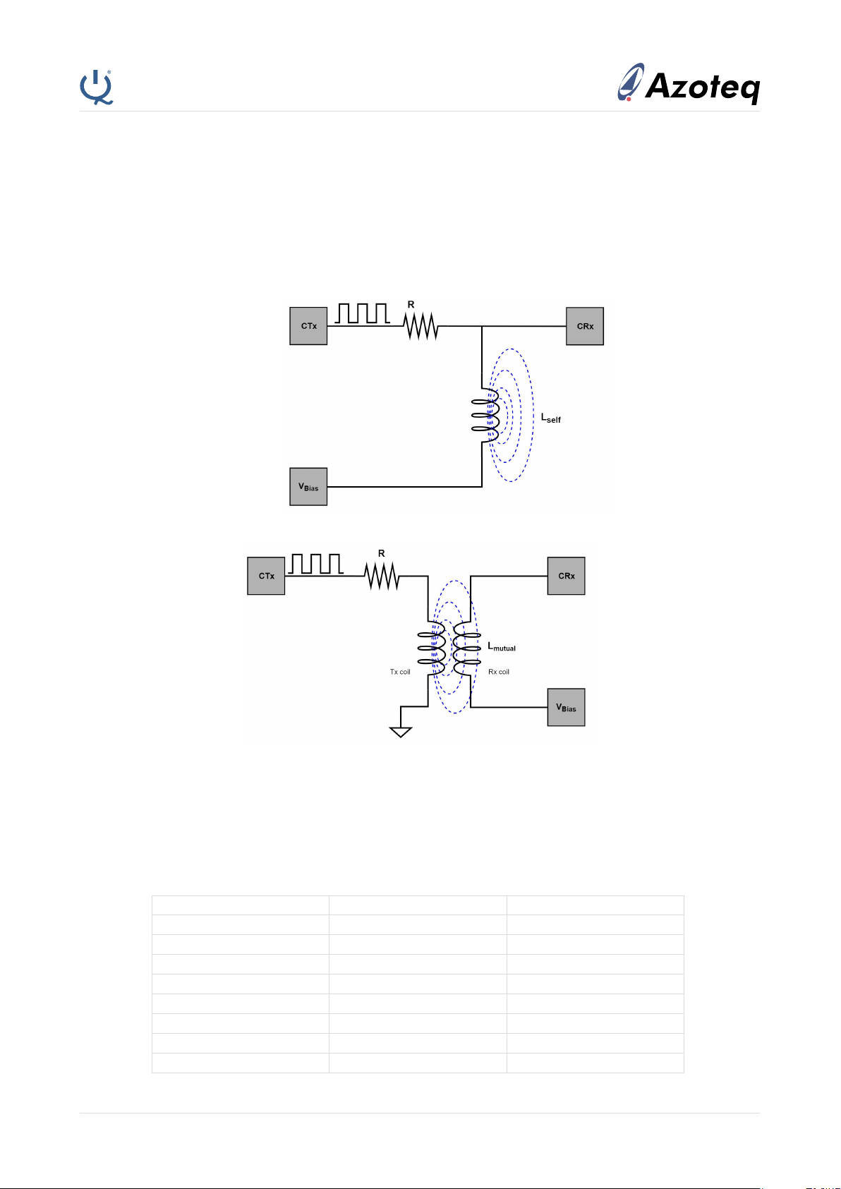
Mutual Inductance
(Biased) 6(2)1 6 Yes 8
Self Inductance
(Biased) 3 3 3 Yes 7
For mutual inductance mode with multiple RX sensors, the change in inductance of one sensor by a metal
target affects the inductance value of the other RX sensors since all the coils are mutual coupled to the
same EM field. Due to the coupling, proximity events over a given sensor should be registered as a relative
change in the inductance. For the self inductance mode, the sensors are not coupled and thus a proximity
event over a sensor can be registered as the absolute change in inductance.
Design choice between mutual and self mode is primarily dependant on the inductive sensing application.
Multiple sensors in the self inductance mode should be used for applications that require absolute read-
ings. Such applications include, encoded event triggers that require a given high-low sequence across the
sensors to register a particular event. Multiple sensors in the mutual inductance mode should be used for
applications that do not require absolute readings. Such applications include, linear position sliders that
indicate the position of a metal target over multiple sensors.
2 Design procedure
•Depending on the inductive sensing application, select either the mutual or the self inductance sens-
ing mode. Refer to Table 2 for the available sensor channels in each mode.
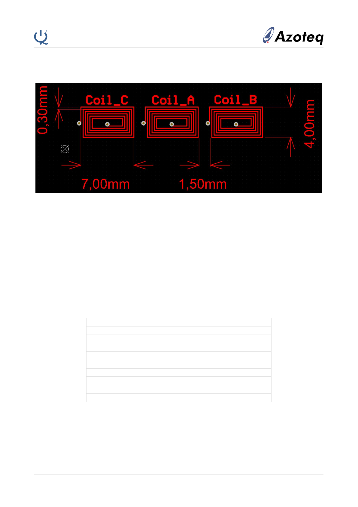
•Determine maximum sensing distance hand design sensor coils with smallest outer diameter Dout
such that Dout ≥2h.
•Select number of turns on each coil such that each coil has the recommended inductance value of
at least 0.5µH. Sensing can be achieved with smaller inductance values, however careful tuning of
the tank circuit and device setting is required. A larger inductance value has little significance on the
sensing range but provides better noise performance.
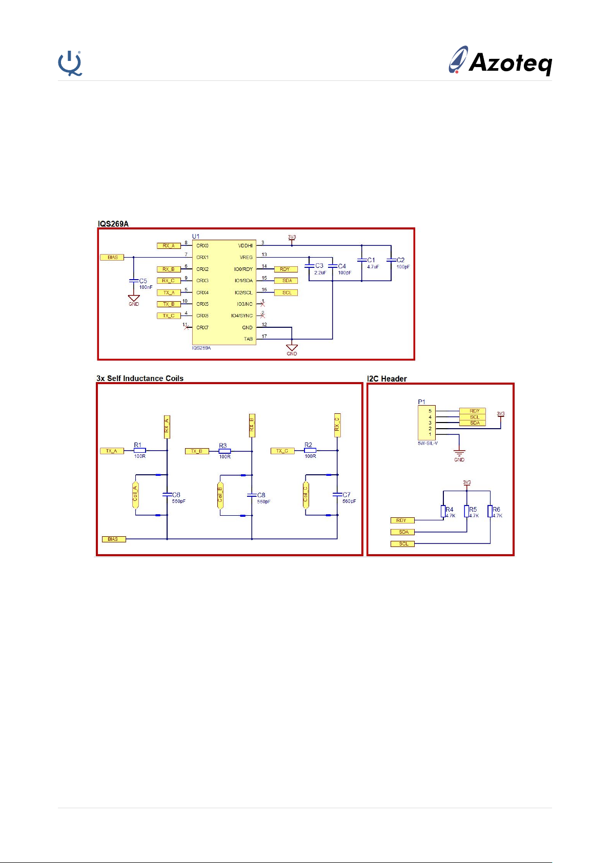
•Implement parallel LC tank circuit with resonant frequency fres.
fres =
1
2π√LC (1)
For the mutual inductance mode, the LC tank can either be implemented on only the Tx coil or on
both the Tx and Rx coils for greater sensitivity.
•Select capacitor value Csuch that fres and the coil excitation frequency ftx satisfy the response
condition
fres ≥ftx (2)
1CRX1 pin is configured as the bias voltage in inductive sensing mode
27 channels if CTx signal is provided externally (E.g. PWM from an MCU)
Copyright c
Azoteq (Pty) Ltd 2019.
All Rights Reserved.
IQS269A Inductive Sensing Quickstart Guide
Revision 1.0
Page 3 of 15
October 2019