Azoteq IQ Switch ProxSens Series User manual

IQ Switch
®
ProxSens
®
Series
Copyright © Azoteq (Pty) Ltd 2012. IQS243 GUI User Manual Page 1 of 5
All Rights Reserved. Revision 1.0 June 2012
IQS243 GUI User Manual
IQ Switch
®
- ProxSense
®
Series
Table of Contents
IQS243 GUI USER MANUAL ......................................................................................................................................... 1
TABLE OF CONTENTS .................................................................................................................................................. 1
1
INTRODUCTION ............................................................................................................................................. 1
2
SETUP ........................................................................................................................................................... 1
3
GUI OPERATION ............................................................................................................................................ 2
1 Introduction
This user manual describes the basic
operation of the IQS243 Graphical User
Interface software. The GUI provides a
platform for rapid prototyping by enabling
application and development engineers to
visualise the real time data stream from the
IQS243 Proximity and Touch Sensor.
2 Setup
.
The IQS243 Software GUI can be downloaded from the following link:
http://www.azoteq.com/images/stories/software/azoteq_iqs243_setup.zip
Plug in the IQS243 module into the IQS243EV02 Mainboard or wire into specific application
Connect the Mainboard to the Azoteq CTxxx or DSxxxDataStreamer
Run the IQS243 Software GUI
The GUI display is illustrated in Figure 2.1. The “Hints and Tips” Pop-up window in the centre of
the screen contains important information relevant to the software GUI and IC, please take the
time to read though all of the information. The scroll buttons can be used to flip through the hints
and tips and are marked in Figure 2.1.
After closing the Hints & Tips window in the centre of the screen, data streaming can be started
by clicking on the “Start” button, as also depicted in Figure 2.1

IQ Switch
®
ProxSense
®
Series
Copyright © Azoteq (Pty) Ltd 2012. IQS243 GUI User Manual Page 2 of 5
All Rights Reserved. Revision 1.0 June 2012
Figure 2.1 IQS243 GUI Startup Screen
3 GUI operation
After data streaming has commenced, the display will appear as illustrated in Figure 3.1. The
channel data is indicated by bar graphs in the centre of the GUI:
Figure 3.1 Data streaming started
Please note the “Event Mode” settings on the right hand side of the IQS243 GUI. When the
IQS243 IC is configured in Event Mode, communication will only commence when the IC registers
Bar Graphs
Event Mode
settings
Scroll Buttons

IQ Switch
®
ProxSense
®
Series
Copyright © Azoteq (Pty) Ltd 2012. IQS243 GUI User Manual Page 3 of 5
All Rights Reserved. Revision 1.0 June 2012
an event, such as a proximity or touch detection event. By default the IC starts up in Event Mode,
however the GUI reconfigures the IC upon GUI start-up, to run in continuous streaming mode.
This provides a fluent and continuous stream of data for prototyping and visualisation. Please see
the IQS243 datasheet for further information regarding Event Mode operation.
The proximity and touch detection levels (thresholds), as well as the overall sensitivity can be
adjusted individually for each channel, in the “Compensation / Multiplier / Thresholds” section of
the GUI, as illustrated in Figure 3.2 below:
Figure 3.2 GUI Settings
The threshold settings will adjust the proximity and touch detection levels, whereas the Multiplier
and Compensation settings will adjust the counts, and thus the overall sensitivity of the device. By
default the ATI algorithm will adjust these values to the optimum settings to reach a target count of
approximately 1000 counts. ATI can be turned off and the settings selected manually. The ATI
settings can be found in the ATI section of the software GUI, as illustrated in the upper right corner
of Figure 3.2.
After the appropriate adjustments have been made to the IC, the settings can be saved to a file for
future use, by making use of the Save/Load function as displayed in the left hand side of Figure
3.2. This enables settings to be loaded from the file, instead of re-adjusting all settings from
scratch.
Proximity and Touch events are indicated in the GUI, by the channel light underneath the
corresponding bar graph. A blue light indicates proximity detection, whilst a red light indicates
touch detection, as illustrated in Figure 3.3.
Threshold
settings
Multiplier and
Compensation
settings
ATI settings
Save/Load settings

IQ Switch
®
ProxSense
®
Series
Copyright © Azoteq (Pty) Ltd 2012. IQS243 GUI User Manual Page 4 of 5
All Rights Reserved. Revision 1.0 June 2012
Figure 3.3 Proximity and Touch indications
To visualise detailed changes in data with respect to time (discrete samples), the “Scope View” can
be enabled by clicking on the “Scope” button, as illustrated in Figure 3.4.
Figure 3.4 Scope View
Each channel’s visibility and colour can be adjusted along with the scale of the scope view, in the
scope view settings section, on the right hand side of the scope view window.
Touch Detection
Proximity Detection
Scope View Enable Channel Data
Scope View settings

IQ Switch
®
ProxSense
®
Series
Copyright © Azoteq (Pty) Ltd 2012. IQS243 GUI User Manual Page 5 of 5
All Rights Reserved. Revision 1.0 June 2012
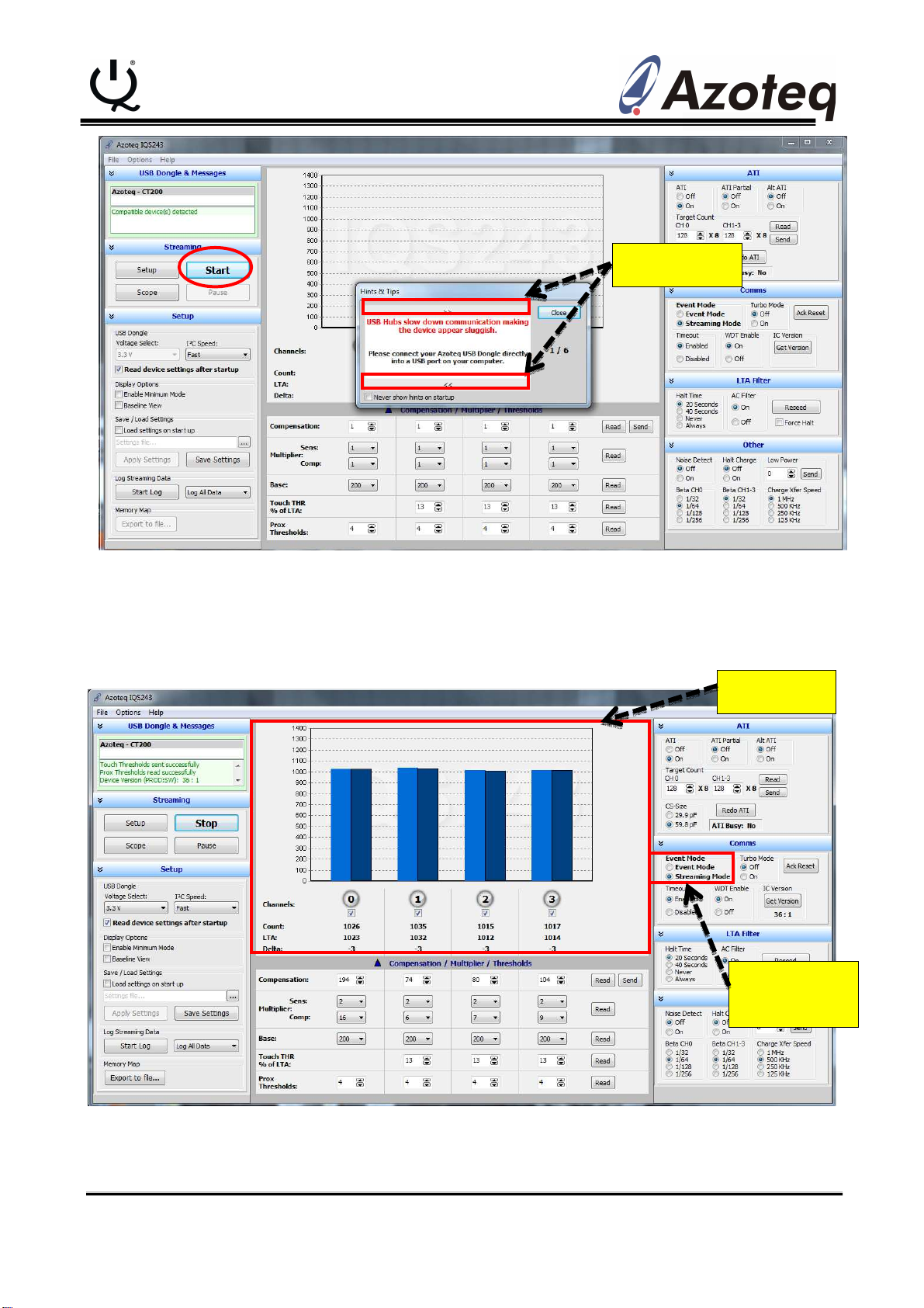
To return to the Bar graph view, simply close out of the scope view window. This can be done by
clicking on the X in the upper right hand corner of the window, or by clicking the “Bar Graph” button
in the lower right hand corner of scope view settings section of the scope view window.
The following patents relate to the device or usage of the device: US 6,249,089 B1, US 6,621,225
B2, US 6,650,066 B2, US 6,952,084 B2, US 6,984,900 B1, US 7,084,526 B2, US 7,084,531 B2,
US 7,119,459 B2, US 7,265,494 B2, US 7,291,940 B2, US 7,329,970 B2, US 7,336,037 B2, US
7,443,101 B2, US 7,466,040 B2, US 7,498,749 B2, US 7,528,508 B2, US 7,755,219 B2, US
7,772,781, US 7,781,980 B2, US 7,915,765 B2, EP 1 120 018 B1, EP 1 206 168 B1, EP 1 308 913
B1, EP 1 530 178 B1, ZL 99 8 14357.X, AUS 761094
IQ Switch
®
, ProxSense
®
, LightSense™, AirButton
®
and the logo are
trademarks of Azoteq.
The information in this Datasheet is believed to be accurate at the time of publication. Azoteq
assumes no liability arising from the use of the information or the product. The applications
mentioned herein are used solely for the purpose ofillustration and Azoteq makes no warranty
or representation that such applications will besuitable without further modification, nor
recommends the use of its products for applicationthat may present a risk to human life due to
malfunction or otherwise. Azoteq products are notauthorized for use as critical components in
life support devices or systems. No licenses topatents are granted, implicitly or otherwise,
under any intellectual property rights. Azoteqreserves the right to alter its products without
prior notification. For the most up-to-dateinformation, please refer to www.azoteq.com.
WWW.AZOTEQ.COM
ProxSenseSuppo[email protected]
This manual suits for next models
1
Table of contents
Other Azoteq Accessories manuals