CeYeKo LUDP User manual

CYK Tech
ULTRASONIC LEVEL SENSOR
User’s Manual
LUDP / LUDR
Copyright © CeYeKo Technology 2021 LUDx_M_V0.0
CYK Tech
www.ceyeko.com
Page 2
Thank you for purchasin ultrasonics level transmitter. Please read this manual
carefully before operating and using it correctly to avoid unnecessary losses
caused by false operation.
Note :
Modification of this manual’s contents will not be notified as a result of some
factors, such as function upgrading.
We try our best to guarantee that the manual content is accurate, if you find
something wrong or incorrect, please contact us.
This product is forbidden to use in explosion-proof occasions.
Versions :
LUDP Compact Version
LUDR Remote Version
P r e f a c e
After opening the box, please confirm the package contents before starting the
operation. If you find that the model and quantity are incorrect or there is physi-
cal damage in appearance, please contact us.
D i s c l a i m e r
No. Name Quantity Note
1Ultrasonic Level
Transmitter 1
2Manual 1
3Certificate 1

CYK Tech
I n s t r u c t i o n s
www.ceyeko.com
Page 3
Notes: as the product is renewed continuously, it cannot be ensured that the
product manual and installation manual are in line with the latest product. The
Company cannot inform every client of the change (if any) in product itself and
its operation instructions. Please directly contact the corporate sales personnel
for any needs. The change includes but is not limited to the following:
Product blind area, performance parameters, functions, structure, shape, co-
lor, etc.
Software functions, structure, display mode, operating habit, etc.
Any operation on the hardware must be conducted after power off. Failures,
like short circuit, caused by power-on operation are beyond the range of
warranty.
The uncapping operations must be conducted after power off and no liquid is
allowed to enter in the meter. Any failure caused by the entering in of liquid
is beyond the range of warranty.
Illustration Description:
This is an important reminder, please read it carefully and follow the require-
ments strictly.
This is a general reminder, please read it carefully so as not to cause trouble
in use

CYK Tech
www.ceyeko.com
Page 4
C o n t e n t s
Preface ……………………………………………………………………………………………………….. 2
Disclaimer ……………………………………………………………………………………………………….. 2
Instructions ……………………………………………………………………………………………… 3
Chapter 1: Product Introduction ………………………………………………………………… 5
Chapter 2: Operating Instructions for Simple Settings ………………………... 5
2.1 Enter the Menu …………………………………………………………………………… 6
2.2 Select Measuring Mode ………………………………………………………………… 7
2.3 Input probe height Value ………………………………………………………………… 7
2.4 Diagram of distance and material level measurement ………………… 7
2.5 Anti-interference Measures ……………………………………………………… 8
Chapter 3: Main Technical Parameter ……………………………………………………… 9
Power Consumption …………………………………………………………………………… 10
Chapter 4: Installation Guide ………………………………………………………………... 11
4.1 Installation Dimension of Level Meter …………………………………… 11
4.1.1 Standard Remote Type Ultrasonic Level Meter ……………… 11
4.1.2 Enhanced Compact Type Ultrasonic Level Meter ………………… 11
4.2 Installation Guide ………………………………………………………………………... 13
4.2.1 Understand Terminology ……………………………………………………... 13
4.2.2 Select Measuring Range ……………………………………………………... 14
4.2.3 Installation of Thread at the Bottom …………………………………… 16
4.2.4 Top Thread Installation-Hoisting Installation ………………………… 17
4.2.5 Liquid Measurement ………………………………………………………………… 17
4.3 Solid Measurement ………………………………………………………………… 22
4.3.1 Flange Installation ………………………………………………………………… 22
4.3.2 Installation via Nipple Joint ……………………………………………………… 23
4.3.3 Doorframe Installation ……………………………………………………… 23
4.3.4 How to Extend the Connecting Pipe for Measurement ……… 24
4.3.5 Installation Should Avoid False Echo …………………………………… 27
4.4 Electric Wiring Diagram ………………………………………………………………… 32
4.4.1 Electric Wiring Diagram Single-Probe Remote-Type ………………… 33
4.4.2 Wiring Diagram of Compact Type ……………………………………………… 35
Chapter 5: Settings …………………………………………………………………………………… 37
5.1 Introduction of Interface of Operation Mode ………………………… 37
Chapter 6: Menu Interface & Operating Instructions …………………………………… 38
Chapter 7: Trobleshooting …………………………………………………………………………… 47
Chapter 8: Fault Causes at Site According to Echo Pattern ………………………… 48
8.1 Resonance …………………………………………………………………………………… 48
8.2 Liquid Enters the Blind Area of Ultrasonic Level Gauge ………………… 49
8.3 Electromagnetic Interference ……………………………………………………… 50
8.4 Effects of Connecting Pipe to Measurement …………………………………… 52
Chapter 9: Modbus Communication Protocol V1.4 Version ………………………… 53

CYK Tech
C h a p t e r 1 : P r o d u c t I n t r o d u c t i o n
www.ceyeko.com
Page 5
Ultrasonic level meter (for material and liquid level measurement) is a non-
contact highly reliable and cost-effective material level measuring instrument
which is easily installed and maintained. It can meet most of the material level
measurement requirements without touching the medium. It is a new generation
ultrasonic level meter with fully independent property rights developed by the
company via years of hard work.
Chapter 2: Operating Instructions for Simple Settings
As the meter installation site environment is different, the basic information of
measurement to be done must be learnt before the operation of the ultrasonic le-
vel meter, such as the measuring range, zero point, full scale and site conditions.
Therefore, the meter must be set before measurement.
Others: please do not modify probe selection, parameter correction and algo-
rithm selection without permission.
Normally the ultrasonic level meter produced by us shall be installed as per the
installation requirements of the manual and after that, the equipment can be nor-
mally used only after the following several parameters are set.
There are three buttons on the panel, via which the meter can be adjusted. The
measured values are displayed on the LCD screen after the adjustment.
SET
Enter Menu Item Exit Menu Item Confirm Parameter Modification
Move Cursor Modify Parameter Choose Menu Item

CYK Tech
www.ceyeko.com
Page 6
2.1 Enter the Menu
After power-on display of the meter, long press the set button (SET) for 2s to
enter in the main menu.
The menu modes include expert setting mode and simply setting mode.
The menu query table of simple setting mode is as shown in the below.
The menu query table of expert setting mode is shown in “VI. Menu Interface &
Operating Instructions: ”.
CYK Tech
www.ceyeko.com
Page 7
2.2 Select Measuring Mode:
Measuring modes are divided into distance measuring mode and material level
measuring mode. And the factory default is material level measurement.
2.3 Input probe height Value :
Input probe height value to “reference zero point” (probe height is the distance from
probe emitting surface to tank bottom or pool bottom).
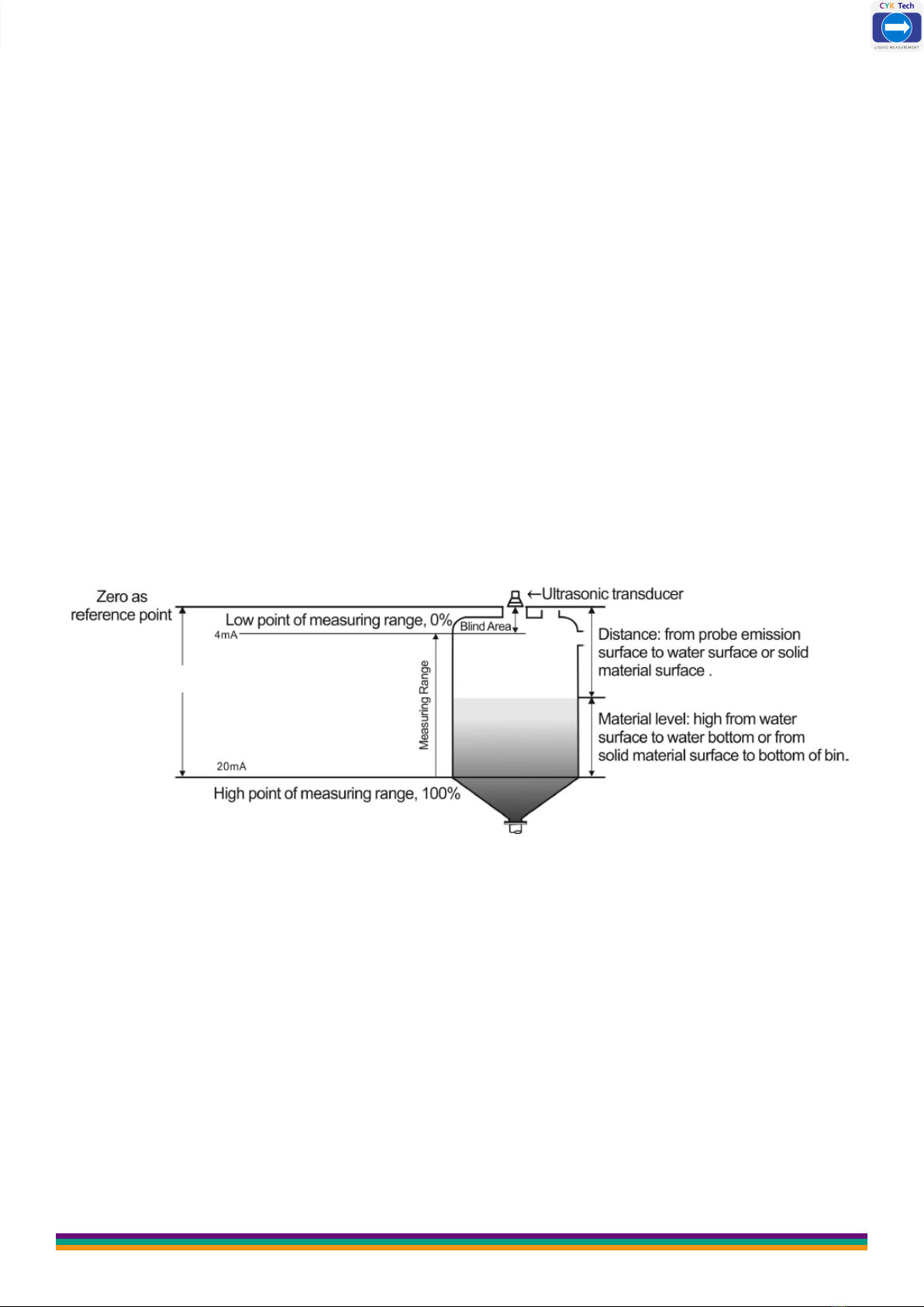
2.4 Diagram of distance and material level measurement
❶ Under distance measuring mode, setting of reference zero point is meaningless
and the positions of maximum of measuring range and minimum of measuring range
are as shown in Fig. 1.1
Distance Measurement Mode; measure the distance from probe emision surface to
water surface, output 4-20 mA corresponds to the variation of distance.
Fig. 1.1 Diagram of Distance Measurement
CYK Tech
www.ceyeko.com
Page 8
After the equipment is installed, it must be grounded separately, don’t use the com-
mon ground of the electrical box or instrument box.
Suggestion: When the ultrasonic level meter is connected to the frequency conver-
ter, PLC and other devices that have interference, an isolation transformer should
be added to the power supply part, and a signal isolator should be added to the sig-
nal part, and reliable grounding should be done.
The signal line must not be installed in the same slot with the power line and
the power line. It must be installed separately through a metal pipe, or instal-
led away from the power line and power line. Under the premise of not being
installed through the pipe, the distance from the power line and power line at
least 1 meter
2.5 Anti-interference Measures:
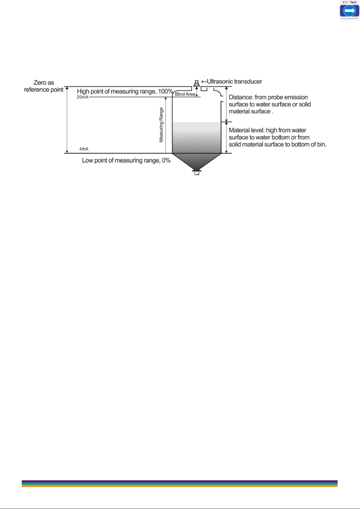
❷ Under material level measuring mode, the positions of reference zero point,
maximum of measuring range and minimum of measuring range are as shown in
Fig. 1.2
Level Measurement Mode; measure the distance from water surface to water bot-
Fig. 1.2 Diagram of Material Measurement Level
Low Point: the distance from the reference plane to this position. When the low
point of the range is higher than the reference plane, the value is positive, and
when it is lower than the reference plane, the value is negative. When the liquid
level is at this position, 4mA current is output.
High Point: the distance from the reference plane to this position. The value is
positive when the range high point is higher than the reference plane, and negative
when it is lower than the reference plane. When the liquid level is at this position,
20mA current is output.
CYK Tech
www.ceyeko.com
Page 9
C h a p t e r 3 : M a i n T e c h n i c a l P a r a m e t e r
Function Compact Type Remote Type
Measuring Range 5m, 10m, 15m, 20m, 30m,
40m, 50m, 60m
5m, 10m, 15m, 20m, 30m,
40m, 50m, 60m, 70m
Measurement
Accuracy 0.5%-1.0%
Resolution Ratio 3mm or 0.1% (whichever is greater)
Display English LCD
Analog Output
4-wire system, 4~20mA/ 510Ω
load
2-wire system, 4~20mA/ 250Ω
4~20mA/ 510Ω load
Relay Output
2 groups (i.e. AC 250V/ 8A or
DC 30V/ 5A) optional, state
programmable
2 groups for single channel and
4 groups for double channels
(optional) AC 250V/ 8A or DC
30V/ 5A, state programmable
Power Supply
Standard configuration: 24VDC
Optional: 220V AC+15% 50Hz
Customized: 12VDC
Standard configuration: 220V
AC+15% 50Hz
Optional: 24VDC 120mA
Customized: 12VDC
Ambient
Temperature
Display instrument: -20~+60ºC
Probe: -20~+80ºC
Communication RS485, RS232 communication (optional)
Ingress Protection Display Instrument: IP65, Probe: IP68
Probe Cable None 100m available, standard
configuration: 10m
Probe
Installation
Select type based on
measuring range and probe
CYK Tech
www.ceyeko.com
Page 10
Power
Consumption
(Remote Type )
The power supply of Remote type is 24V power and the electri-
city consumed for such type is 100mA without relay,
150mA with 2 relays, 200mA with 4 relays.
Specific power consumed is shown in below:
24V×100mA=2.4W for remote type without relay;
24V×150mA=3.6W for remote type with 2 relays;
24V×200mA=4.8W for remote type with 4 relays;
Power
Consumption
(Compact Type)
The integrated type with four-wire system is powered by 24V
power supply and its electricity consumed is 80mA without relay,
105mA with a relay and 150mA with 2 relays.
Specific power consumed is shown in below:
24V×80mA=1.92W for integrated type without relay;
24V×150mA=3.6W for integrated type with 2 relays;
Power
Consumption
(Compact Type)
The integrated type with two-wire system is powered by 24V
power supply. It cannot be equipped with relay and its electricity
consumed is 20mA.
Specific power consumed is shown in below:
24×20mA=0.48W for integrated type without relay;
Power Consumption
CYK Tech
www.ceyeko.com
Page 11
C h a p t e r 4 : I n s t a l l a t i o n G u i d e
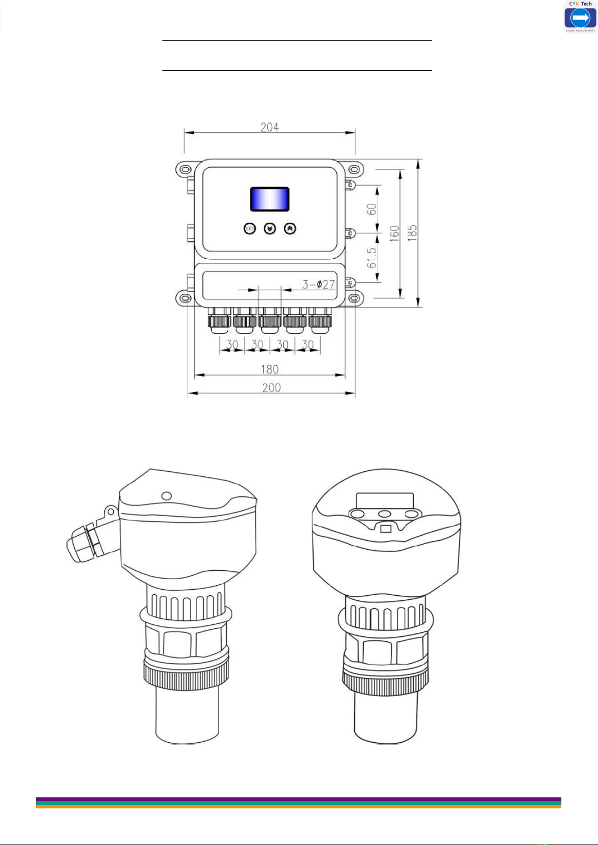
4.1 Installation Dimension of Level Meter
4.1.1 Standard Remote Type Ultrasonic Level Meter:
Structural Drawing
4.1.2 Enhanced Compact Type Ultrasonic Level Meter:
Side Picture Front Picture

CYK Tech
www.ceyeko.com
Page 12

CYK Tech
www.ceyeko.com
Page 13
4.2 Installation Guide
4.2.1 Understand Terminology :
❶ Measuring Range: The meaning of measuring range is very important for
meter type selection. Please refer to the diagrams below.
❷ Emitting Angle and False Echo
Ultrasonic wave beam is gathered by the probe. The emitting of impulse wave beam
is like the light beam of flashlight. The further it is from the probe, the greater the
diffusion area is.
Any objects within the launch angle, such as pipes, brackets, welds, stiffeners, stir-
ring propellers, and wall-mounted objects, will cause strong false echoes, especially
objects closer to the probe within the launch angle.
For example: the false echo caused by a pipe at a distance of 6 meters from the
probe is 9 times stronger than the false echo caused by the same pipe at a distance
of 18 meters from the probe.
Try to make the axis of the sensor perpendicular to the surface of the medium,
and avoid any other objects within the emission angle. Such as: pipes and brac-
kets.
CYK Tech
www.ceyeko.com
Page 14
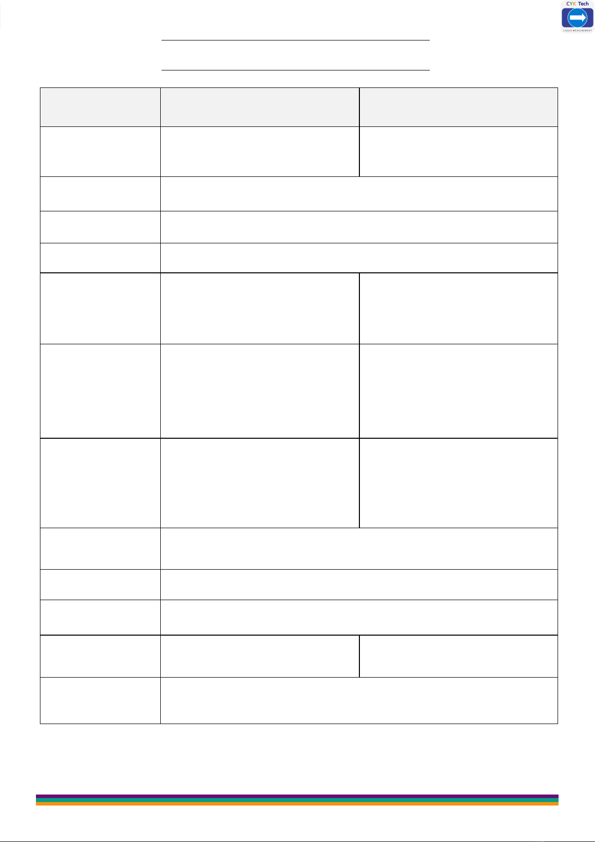
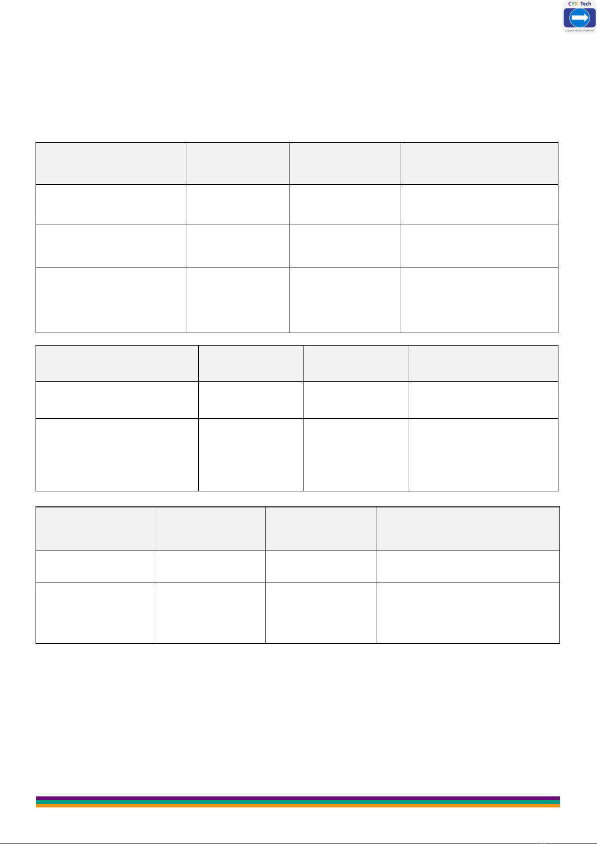
4.2.2 Select Measuring Range:
Measuring range is decided by the range of ultrasonic probe which is subject to the
site working environment, object to be measured and temperature, etc. Decide the
measuring range needed based on the table below.
Liquid Surface Attenuation
Multiple
Attenuation
Percentage
Magnification of
Measuring Range
Stable 0dB 0% Magnification is
unnecessary
Ripple 5...10dB 50~67% 1 times of the
measuring range
Major fluctuation (for
example, there is
mixing blade)
10...20dB 90% 3 times of the
measuring range
Solid Material Surface Attenuation
Multiple
Attenuation
Percentage
Magnification of
Measuring Range
Hard, rough (such as gra-
nular rubber) 40dB 99% 10 times of the
measuring range
Soft (such as pulverized
coal, cement and coal
ash)
40...60dB 99~99.9% Use not
recommended
With Dust Attenuation
Multiple
Attenuation
Percentage
Magnification of
Measuring Range
None 0dB 0% Magnification is unnecessary
Little 5dB 50% 1 times of the
measuring range
CYK Tech
www.ceyeko.com
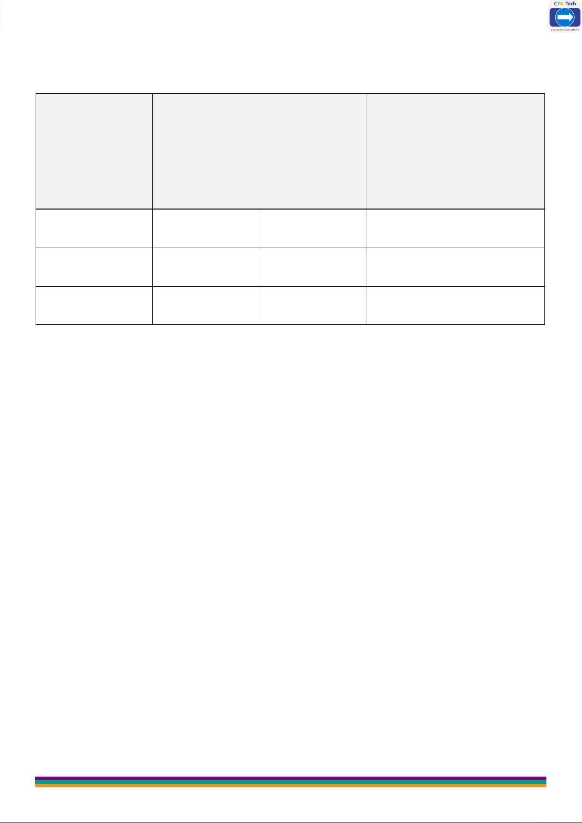
Page 15
Temperature Diffe-
rence Between
Probe and Medium
Surface
Attenuation
Multiple
Attenuation
Percentage
Magnification of
Measuring Range
≤20°C 0dB 0% Magnification is unnecessary
≤40°C 5...10dB 50~67% 1 times of the
measuring range
≤80°C 10…20dB 67~90% 2 times of the
measuring range
The calculation method of signal attenuation is to add all signal attenuation amounts
if there are several conditions on site.
With little feedstock 5...10dB
With little steam 5...20dB
Temperature difference between probe and medium surface ≤40ºC
5...10dB
Total minimum: 15dB
maximum: 40dB
Under such circumstances, if the actual maximum measuring range is 5m,
ultrasonic level meter with measuring range of 50m shall be selected for the
measurement.
CYK Tech
www.ceyeko.com
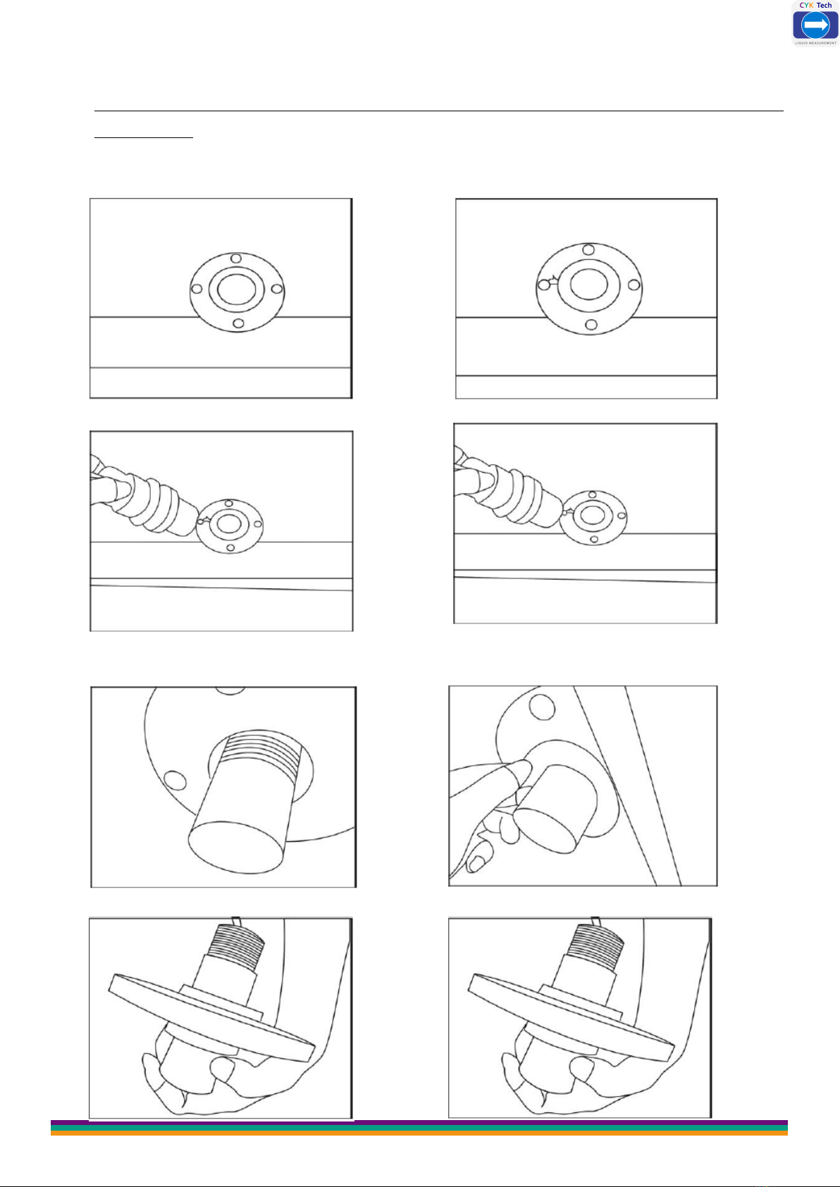
4.2.3 Installation of Thread at the Bottom :
It is recommended to use plastic flange to connect with the sensor during the
installation.
01.Install a flange on the object
to be measured
02.Place a spacer of the same in-
ner diameter on the flange
03.Align the transducer with flange hole 04.Place the transducer in flange hole
05.See from the flange bottom 06.Place a spacer of the same
inner diameter under the flange
Page 16
07.Tighten nuts to fix the transducer 08.Transducer installed

CYK Tech
Page 17
4.2.4 Top Thread Installation-Hoisting Installation:
Installation on the tank, pool, cover plate and support is basically the same as
above.
After probe installation, the probe emission surface must be exposed from the
cover plate or waveguide and it shall not be in the cover plate or waveguide.
02.Put a gasket on the flange
4.2.5 Liquid Measurement:
(1) Flat-Top Tank
Normally, the flat-top tank has a short connecting pipe whose datum plane is the un-
dersurface of flange. Under the premise that the connecting pipe length is ≤60mm,
inner diameter is ≥100mm and inner wall is smooth and free of burr and bulges, the
measurement can be carried out if the emitting surface of installed probe is 3cm be-
low the flange undersurface.
Flange installation in a short connecting pipe
www.ceyeko.com

CYK Tech
www.ceyeko.com
Page 18
The most ideal installation is to directly install the meter on the flat-top container
without using the connecting pipe and the round opening on the container is good
enough for the fixing of mounting flange or cardan joint. The probe emitting surface
is below the datum plane.
Similarly, the remote type sensor can be installed via top hoisting thread and the di-
mensions of hoisting thread include M30×1.5, M32×1.5 and M38×1.5.
Probe installation on nipple joint Hoisting thread connection at the remo-
te type probe top
In case of installation on nipple joint similar to a probe, the inner diameter of con-
necting pipe shall be identical to the external thread and the probe emitting surface
must be exposed for at least 1cm from the connecting pipe and it shall not be inside
the connecting pipe.
Flange-type (locking flange) installation
on the flat-top tank
Flange-type installation on the flat-top
tank without connecting pipe

CYK Tech
www.ceyeko.com
Page 19
Installation on nipple joint – arch tank
top
Installation on flange – arch tank top
(2) Arch Top Tank
For arch tank, it’s better not to install the meter in the middle of the tank top. Ins-
tead, the meter shall be installed at 1/2 or 2/3 of the tank top radius (under the pre-
mise that certain distance from the tank wall is met). The arch tank top is like con-
vex lens to the ultrasonic pulse. If the probe is installed at the focus of convex lens,
it will receive all the false echoes. Therefore, the sensor shall not be installed in the
middle of the arch tank top.
For most arch tanks, the length of connecting pipe plus flange on the top is 150-
180mm. But the part below the probe thread of ultrasonic level meter is not so long
(elongated probe is available for customization to make sure the probe emitting sur-
face is below the connecting pipe bottom). In this case, the proportional relation
between the diameter and length of connecting pipe shall be noted.
#Length of Con-
necting Pipe
Minimum In-
ner Diameter
of Connecting
Pipe
Remarks
1150mm 100mm The inner wall of connecting pipe is free of
burr and bulges and vertical and the weld
joint shall be polished.
The connection of connecting pipe and tank
top shall be outwards polished at an oblique
angle of 45º.
2200mm 150mm
3250mm 180mm
4300mm 220mm
5400mm 280mm

CYK Tech
www.ceyeko.com
Page 20
(3) Arch Top Tank
For open container, the support shall be used for installation. The bearing capacity of
support shall be noted and certain distance shall be kept between the sensor and
container wall. If the upper part and lower part of the open container or stock bin in-
ner wall are flat and free of hanging objects and any other objects, the distance
between the sensor and container wall is detailed as follows:
Maximum
Measuring
Range
Minimum
Distance to
Wall
Maximum
Measuring
Range
Minimum
Distance to
Wall
Maximum
Measuring
Range
Minimum
Distance to
Wall
5m 0.6m 10m 1.2m 15m 1.8m
20m 2.5m 30m 3.5m 40m 5m
50m 6m 60m 7m 70m 8m
Installation on open container –
with top against the support at
one side
As the open container has no focusing effect, the sensor can be installed in the
middle of the container.
Installation on open container –
with support at the top middle
part
This manual suits for next models
1
Table of contents


