Azoteq IQ Switch - ProxSense Series Owner's manual

Copyright © Azoteq (Pty) Ltd 2013
AZD070 –IQS5xx Programming and GUI
(data streaming) Guide
Page 1 of 18
All Rights Reserved
Revision 0.2
February 2014
IQ Switch®
ProxSense® Series
Application Note: AZD070
IQ Switch®- ProxSense®Series
IQS5xx Programming and GUI (data streaming) Guide
Contents
1OVERVIEW .....................................................................................................................................................2
1.1 PROXSENSE®IQS5XX SERIES –FEATURES...................................................................................................................2
1.2 IQS5XX SERIES DEVICES ..........................................................................................................................................2
2IQS5XX FIRMWARE PROGRAMMING .............................................................................................................3
2.1 IQS5XX FIRMWARE UPLOAD:................................................................................................................................... 3
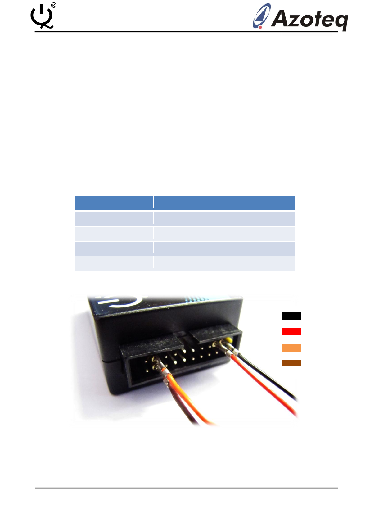
2.2 IQS5XX CONNECTION:............................................................................................................................................ 3
2.3 NRST PULL-UP ......................................................................................................................................................4
2.4 TROUBLESHOOT:....................................................................................................................................................5
3IQS5XX (I2C) COMMS SETUP...........................................................................................................................7
3.1 IQS5XX (I2C) SETUP............................................................................................................................................... 7
3.2 IQS5XX CONNECTION:............................................................................................................................................ 7
3.3 TROUBLESHOOT:....................................................................................................................................................8
4IQS5XX GUI SETUP: ........................................................................................................................................9
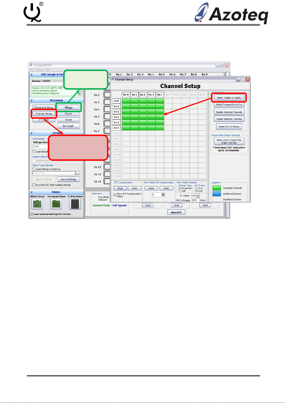
4.1 “START”AND “CHANNEL SETUP”..............................................................................................................................9
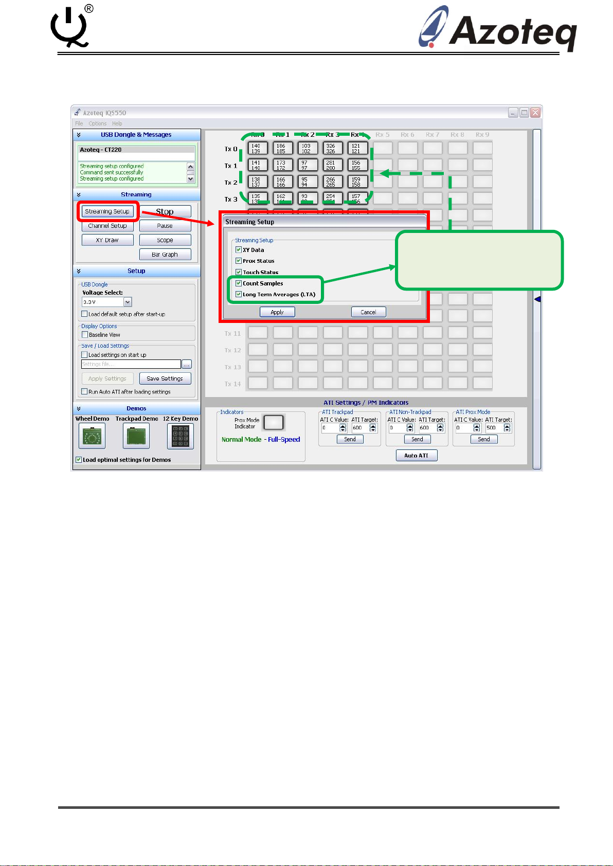
4.2 CHANNEL DATA (STREAMING SETUP)....................................................................................................................... 10
4.3 “ATI TARGET”&“ATI CVALUE”(BASE VALUE) .......................................................................................................11
4.4 PROXIMITY &TOUCH THRESHOLDS .........................................................................................................................12
4.5 PROX HARDWARE SETTINGS .................................................................................................................................13
4.6 TIMINGS,FILTERS &DEBOUNCE .............................................................................................................................14
4.7 SAVE SETTINGS &“AUTO ATI”...............................................................................................................................15
5IQS5XX GUI FEATURES .................................................................................................................................16
5.1 BAR GRAPH AND SCOPE VIEW ................................................................................................................................16
5.2 XY DRAW ...........................................................................................................................................................17

Copyright © Azoteq (Pty) Ltd 2011.
AZD070 –IQS5xx Programming and GUI
(data streaming) Guide
Page 2 of 18
All Rights Reserved.
Revision 0.2
February 2014
IQ Switch®
ProxSense® Series
1 Overview
1.1 ProxSense® IQS5xx series –Features
The IQS5xx Series ProxSense® devices are fully integrated capacitive touch and proximity sensors with
market leading sensitivity and automatic tuning on all the sense electrodes. The device is ready for use in a
large range of applications while the I2C compatible interface provides full control to a host. Active low-
power options are available with superior proximity sensing range for device wake up.
Main Features
Proximity, touch and snap on each channel
Swift report rates1
I2C™(400kHz) compatible communication interface
ATI: automatic tuning to optimum sensitivity
Supply Voltage 1.65V to 3.6V
Active low power operation (<10uA)2
Event-driven / Continuous data I2C™operation
Dedicated proximity channel for superior proximity sensing
Internal voltage regulator and reference capacitor (minimal external components required)
On-chip noise detection and suppression
1Report rates are dependent on the number of active channels etc. (Please refer to IQS5xx datasheet).
2 Current consumption is dependent on device configuration and selected power mode.
1.2 IQS5xx Series Devices
The ProxSense® IQS5xx series consist of the IQS512, IQS525, IQS572 and IQS550 devices.
DEVICE
FEATURES
IQS512
Projected Capacitive Sensor with up to 12-channels, X-Y Tracking,
Snap (Click).
IQS525
Projected Capacitive Sensor with up to 25-channels, X-Y Tracking,
Snap (Click).
IQS572
Projected Capacitive Sensor with up to 72-channels, X-Y Tracking,
Snap (Click).
IQS550
Projected Capacitive Sensor with up to 150-channels, X-Y Tracking,
Snap (Click).
IQS5xx Datasheets, Application Notes and other ProxSense®information available from:
www.azoteq.com

Copyright © Azoteq (Pty) Ltd 2011.
AZD070 –IQS5xx Programming and GUI
(data streaming) Guide
Page 3 of 18
All Rights Reserved.
Revision 0.2
February 2014
IQ Switch®
ProxSense® Series
2 IQS5xx Firmware Programming
2.1 IQS5xx Firmware Upload:
The following steps are required for programming the IQS5xx devices:
Connect the GND, VDDHI, NRST and PGM pins to the CT210 (or later) USB Dongle.
Connect the USB dongle to your PC or laptop computer.
Run the AZOTEQ FLASH PROGRAMMER software.
Load the “IQS5xx_firmware”.hex file.
Click the “Connect to Device” button.
Click the “Program” button to program the IQS5xx device.
2.2 IQS5xx Connection:
IQS5xx Pins
CT210 –or later (Azoteq Configuration Tool)
GND
CT210 –pin1
VDDHI
CT210 –pin3
NRST
CT210 - pin17
PGM
CT210 - pin18
GND
VDDHI
NRST
PGM

Copyright © Azoteq (Pty) Ltd 2011.
AZD070 –IQS5xx Programming and GUI
(data streaming) Guide
Page 4 of 18
All Rights Reserved.
Revision 0.2
February 2014
IQ Switch®
ProxSense® Series
2.3 NRST pull-up
If the application PCB has the suggested 100nF (or similar) capacitor populated on NRST, it might
be required to add a 1k pull-up resistor to the programming wires (between NRST and VDDHI).
On the latest CT210 programming tools the pull-up is populated, however on some older hardware
versions this pull-up is still required.
Alternatively you can populate the actual resistor on the CT210 PCB. You must populate R68 on
board AZT231A02 as shown in the pictures below. R68 is populated on the bottom side of the
PCB.

Copyright © Azoteq (Pty) Ltd 2011.
AZD070 –IQS5xx Programming and GUI
(data streaming) Guide
Page 5 of 18
All Rights Reserved.
Revision 0.2
February 2014
IQ Switch®
ProxSense® Series
2.4 Troubleshoot:
Connection error:
•No device connected
•Please check NRST and PGM line connections.
•Click “Program” again to program IQS5xx device.
•Repeat next step if error occurs again.
•Make sure you have a pull-up resistor modification if you have a large capacitor
on NRST, see Section 2.3.
•If problem persists, please contact ProxSense® support.

Copyright © Azoteq (Pty) Ltd 2011.
AZD070 –IQS5xx Programming and GUI
(data streaming) Guide
Page 6 of 18
All Rights Reserved.
Revision 0.2
February 2014
IQ Switch®
ProxSense® Series
Programming error:
•Error Code 4103 - Error while erasing device
•Please check NRST and PGM line connections.
•Click “Program” again to program IQS5xx device.
•Repeat previous step if error occurs again.
•If problem persists, please contact ProxSense® support.

Copyright © Azoteq (Pty) Ltd 2011.
AZD070 –IQS5xx Programming and GUI
(data streaming) Guide
Page 7 of 18
All Rights Reserved.
Revision 0.2
February 2014
IQ Switch®
ProxSense® Series
3 IQS5xx (I2C) Comms Setup
3.1 IQS5xx (I2C) Setup
The following steps are required for I2C data streaming on the IQS5xx devices:
Connect the GND, VDDHI, SDA, SCL and RDY pins to the DS100 or CT210 (or later) USB Dongle.
Connect the USB dongle to your PC or laptop computer.
Run the IQS5xx GUI software and click “Start”. (See Section 3.4)
Channel Setup (Select Active Channels)
Streaming Setup (Select Channel Data)
Select ATI C value (i.e. configure Base Value)
Select ATI Target Value.
Select Proximity and Touch Thresholds.
Setup PROX Hardware Settings
Setup Timings and Filters
Save your settings and click “Auto ATI”
Device is now operational
3.2 IQS5xx Connection:
IQS5xx Pins
DS100/CT210 (Azoteq Data Streamer /
Configuration Tool)
GND
CT210 –pin1
VDDHI
CT210 –pin3
SDA
CT210 –pin7
SCL
CT210 –pin9
RDY
CT210 –pin10
GND
VDDHI
SDA
SCL
RDY

Copyright © Azoteq (Pty) Ltd 2011.
AZD070 –IQS5xx Programming and GUI
(data streaming) Guide
Page 8 of 18
All Rights Reserved.
Revision 0.2
February 2014
IQ Switch®
ProxSense® Series
3.3 Troubleshoot:
Streaming error:
Warning: Unable to start device streaming!
Please check I2C communication line (SDA, SCL and RDY) connections.
Check pull-up resistors on I2C lines (typ. 10kΩ).
Click “Start” again to start IQS5xx data streaming.
If problem persists, please contact ProxSense® support.

Copyright © Azoteq (Pty) Ltd 2011.
AZD070 –IQS5xx Programming and GUI
(data streaming) Guide
Page 9 of 18
All Rights Reserved.
Revision 0.2
February 2014
IQ Switch®
ProxSense® Series
4 IQS5xx GUI setup:
4.1 “Start” and “Channel Setup”
Normal GUI use:
Click “Start”
You can touch the capacitive area after the Start button is clicked.
Running a Demo:
Click “Start”
Click the picture of the demo used, follow prompts in additional pop-up windows.
Setting up Channels
Select Total of Tx’s and Rx’s used for both the Trackpad and Additional sensors (if used).
If additional sensors are used outside the Trackpad area, the Trackpad area will also need to be
selected. Note that the Trackpad area will remain green, while the Additional sensor channels
are changed to a blue colour (see “Legend”).
To disable channels, first select the channels to disable then click the “Disable Selected
Channels”button.
If a Prox channel is needed, it can be setup in the “Prox Mode Channel” text box area. Please
refer to the IC specific datasheets to set up the channel(s).
1. START
2. Select Active
Channels
* Click and Drag to Select Channels

Copyright © Azoteq (Pty) Ltd 2011.
AZD070 –IQS5xx Programming and GUI
(data streaming) Guide
Page 10 of 18
All Rights Reserved.
Revision 0.2
February 2014
IQ Switch®
ProxSense® Series
4.2 Channel Data (Streaming Setup)
CS (Count) and LTA (Long-Term Average) values are used for debugging and tuning of the Trackpad
sensors.
Take note that the response rate will be affected so streaming of CS and LTA data should be
disabled when not needed.
Tick the desired boxes for
required channel data.

Copyright © Azoteq (Pty) Ltd 2011.
AZD070 –IQS5xx Programming and GUI
(data streaming) Guide
Page 11 of 18
All Rights Reserved.
Revision 0.2
February 2014
IQ Switch®
ProxSense® Series
4.3 “ATI Target” & “ATI C Value” (Base Value)
Tuning the Trackpad for the first time:
In the ATI Settings panel below the sensor display area, set the “ATI C” and “ATI Target”
values to 0 for “ATI Trackpad”, then Click Send and then Auto ATI.
Now an indication of the amount of parasitic capacitance present in the circuit can be
obtained by looking at the CS value (Base Value when: ATI C = 0, ATI Target = 0).
The sensors of a well designed trackpad will have a uniformly distributed CS count in a
range of 10-15% of each other. The higher the base count the more parasitic
capacitance there is present in the circuit.
Select an “ATI C” value to obtain a CS value equal to approximately ¼ of the target
value (Typical target for high sensitivity = 900-1000 counts).
Higher target values induce slower response rates and vice versa (depending of
number of active channels etc).
Adjust the ATI C and Target values to get the desired response rate and sensitivity.
*Note: The response rate of the IQS5xx devices are influenced by several factors, including
number of active channels, amount of streamed data, ATI Target Value, CS filtering
and other processing options. Please contact Azoteq for assistance or more
information at: ProxSenseSupport@azoteq.com
Select “ATI C value”(Base Value)
and “ATI Target Value”.

Copyright © Azoteq (Pty) Ltd 2011.
AZD070 –IQS5xx Programming and GUI
(data streaming) Guide
Page 12 of 18
All Rights Reserved.
Revision 0.2
February 2014
IQ Switch®
ProxSense® Series
4.4 Proximity & Touch Thresholds
Select the required Proximity and Touch Thresholds from the thresholds selection panel (the
Settings panel is “activated” by the arrow on the right hand side of the GUI window).
Proximity Thresholds are specified in Counts.
Touch Thresholds are calculated as a fraction of the Long-Term Average (LTA) value, using the
equation:
𝑻𝒐𝒖𝒄𝒉 𝑻𝒉𝒓𝒆𝒔𝒉𝒐𝒍𝒅 = (𝒙 𝟐𝒚)
×𝑳𝑻𝑨
For this example the Proximity Thresholds will be PTH = 10 counts, whereas the Touch Threshold will
be TTH = 5/128 * LTA ≈ 40 counts (x = 5; y = 7; LTA ≈ 1000).
Note there are different touch thresholds for different touch areas, such as Trackpad and Non-
Trackpad areas.
Select Required Proximity and
Touch Thresholds

Copyright © Azoteq (Pty) Ltd 2011.
AZD070 –IQS5xx Programming and GUI
(data streaming) Guide
Page 13 of 18
All Rights Reserved.
Revision 0.2
February 2014
IQ Switch®
ProxSense® Series
4.5 PROX Hardware Settings
PROX Hardware Settings may be adjusted to obtain the required Transmit (TX) signal, so as to
acquire sufficient charge transfer.
Please note that changing these settings is not advised without sufficient knowledge of the
device’s sensing mechanisms. Please contact Azoteq at ProxSenseSupport@azoteq.com
*Oscilloscope capture

Copyright © Azoteq (Pty) Ltd 2011.
AZD070 –IQS5xx Programming and GUI
(data streaming) Guide
Page 14 of 18
All Rights Reserved.
Revision 0.2
February 2014
IQ Switch®
ProxSense® Series
4.6 Timings, Filters & Debounce
Timing values may be set according to the requirements of the application.
Typical filtering of the CS count data is performed by the “NormalMode Count Filter” and “NM
Count” filter value.
Debouncing of Proximity and Touch events are configured by the number of “Set” and “Clear”
samples.
Please refer to device specific datasheets for more information on these settings.

Copyright © Azoteq (Pty) Ltd 2011.
AZD070 –IQS5xx Programming and GUI
(data streaming) Guide
Page 15 of 18
All Rights Reserved.
Revision 0.2
February 2014
IQ Switch®
ProxSense® Series
4.7 Save Settings & “Auto ATI”
The configured settings can be saved as a “.ini”file, which can be loaded on start-up.
Click the “Auto ATI” button to redo the ATI (Antenna Tuning Implementation) algorithm.
The device should now be fully set-up and ready for use.
2. Click “Auto ATI”
1. Save Settings

Copyright © Azoteq (Pty) Ltd 2011.
AZD070 –IQS5xx Programming and GUI
(data streaming) Guide
Page 16 of 18
All Rights Reserved.
Revision 0.2
February 2014
IQ Switch®
ProxSense® Series
5 IQS5xx GUI Features
5.1 Bar Graph and Scope View
In the Channel Setup Window, click “Select active Scope & Bar Graph channels”.
Hold “ctrl” key and click the desired channels to be viewed.
Click the “Bar Graph” or “Scope” buttons to view channel data in the respective formats.

Copyright © Azoteq (Pty) Ltd 2011.
AZD070 –IQS5xx Programming and GUI
(data streaming) Guide
Page 17 of 18
All Rights Reserved.
Revision 0.2
February 2014
IQ Switch®
ProxSense® Series
5.2 XY Draw
Click the “XY Draw” button to enable the XY Draw window.
Select the appropriate “Drawing” and “XY Options” in the panel on the right.
Multi-touch/-draw functionality allowed on most IQS5xx devices.

Copyright © Azoteq (Pty) Ltd 2011.
AZD070 –IQS5xx Programming and GUI
(data streaming) Guide
Page 18 of 18
All Rights Reserved.
Revision 0.2
February 2014
IQ Switch®
ProxSense® Series
For more information on ProxSense®IQS5xx Series devices, please contact
Azoteq or your local distributor of Azoteq ProxSense®devices.
The following patents relate to the device or usage of the device: US 6,249,089 B1, US 6,621,225 B2, US 6,650,066 B2, US
6,952,084 B2, US 6,984,900 B1, US 7,084,526 B2, US 7,084,531 B2, US 7,119,459 B2, US 7,265,494 B2, US 7,291,940 B2, US
7,329,970 B2, US 7,336,037 B2, US 7,443,101 B2, US 7,466,040 B2, US 7,498,749 B2, US 7,528,508 B2, US 7,755,219 B2, US
7,772,781, US 7,781,980 B2, US 7,915,765 B2, EP 1 120 018 B1, EP 1 206 168 B1, EP 1 308 913 B1, EP 1 530 178 B1, ZL 99
8 14357.X, AUS 761094
IQ Switch®, ProxSense®, LightSense™, SwipeSwitch™, AirButton® and the logo are trademarks of Azoteq.
The information in this Datasheet is believed to be accurate at the time of publication. Azoteq assumes no liability
arising from the use of the information or the product. The applications mentioned herein are used solely for the
purpose of illustration and Azoteq makes no warranty or representation that such applications will be suitable
without further modification, nor recommends the use of its products for application that may present a risk to
human life due to malfunction or otherwise. Azoteq products are not authorized for use as critical components in life
support devices or systems. No licenses to patents are granted, implicitly or otherwise, under any intellectual
property rights. Azoteq reserves the right to alter its products without prior notification. For the most up-to-date
information, please refer to www.azoteq.com.
WWW.AZOTEQ.COM
ProxSenseSupport@azoteq.com
Other manuals for IQ Switch - ProxSense Series
15
This manual suits for next models
5
Table of contents
Other Azoteq Accessories manuals