Azoteq AZBAT24100C User manual

Copyright © Azoteq (Pty) Ltd 2022
AZBAT24100C User Manual
Page 1 of 13
All Rights Reserved.
Revision 1.02
September 2022
Azoteq
PowerSense®Series
Lithium-Iron Phosphate Battery
AZBAT24100C
Product Manual
This product manual provides further detail on the AZBAT24100C LiFePO4 battery. Please
familiarise yourself with the operating instructions in this document before operating the battery.
Table of Contents
REVISION HISTORY................................................................................................................................. 2
DISCLAIMER ............................................................................................................................................ 2
OVERVIEW................................................................................................................................................ 2
PRODUCT INFORMATION....................................................................................................................... 4
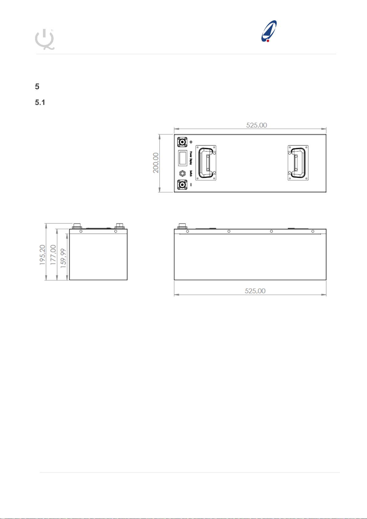
PRODUCTION DIMENSIONS.............................................................................................................4
PARAMETERS................................................................................................................................5
BATTERY INTERFACE.....................................................................................................................6
INSTALLATION ........................................................................................................................................ 7
HARDWARE REQUIRED...................................................................................................................7
INSTALLATION LOCATION ...............................................................................................................8
INSTALLATION PROCEDURE ...........................................................................................................8
PARALLEL CONNECTION.................................................................................................................8
SERIES CONNECTION.....................................................................................................................9
TROUBLESHOOTING .............................................................................................................................. 9
BATTERY PACK VOLTAGE IS LOW OR ZERO................................................................................... 10
INSUFFICIENT ENERGY CAPACITY................................................................................................ 10
PRECAUTIONS....................................................................................................................................... 11
STORAGE .................................................................................................................................. 11
SAFETY ..................................................................................................................................... 11
Before use ....................................................................................................................................11
During use ....................................................................................................................................11
Other.............................................................................................................................................12
EMERGENCY CONDITIONS.................................................................................................................. 12
LEAKING CELLS.......................................................................................................................... 12
FIRE.......................................................................................................................................... 12
OTHER ...................................................................................................................................... 12

Copyright © Azoteq (Pty) Ltd 2022
AZBAT24100C User Manual
Page 2 of 13
All Rights Reserved.
Revision 1.02
September 2022
Azoteq
PowerSense®Series
Revision History
Version
Release date
Change Notes
1.00
18 May 2022
Creation
1.01
04 August 2022
Troubleshooting, Installation and Parameters
1.02
10 August 2022
Website Warranty Link
Disclaimer
This product manual provides further detail on the AZBAT24100C LiFePO4 battery. Please read the
operating instructions in this document before using the battery. Also familiarise yourself with the
warranty conditions of this product to ensure it is operated within stipulated requirements.
Please complete the battery registration from the Azoteq website to activate your warranty.
(https://www.azoteq.com/warranty/)
Overview
The AZBAT24100C incorporates 8x3.2V 100Ah (8S1P configuration) Lithium-Iron Phosphate
(LiFePO4) cells with a recommended 0.3C charge and 0.5C discharge current rating. The battery
incorporates a battery management system (BMS) which provides the following functionality:
•Protection
oCell overcharge and discharge
oShort circuit
oOver and under temperature
oTotal over- and under-voltage
•Control
oCell balancing
The BMS has been tested with leading inverters, including Synapse, Voltronic and GroWatt and has
been UN38.3 and IEC 62619 certified.
The battery is mounted in a durable steel casing with spring loaded handles for easy handling. It
features a LCD display* with an display on/off button. The battery is fitted with M8 terminal
connections for sturdy connection to the battery cables.
*The SoC displayed on the LCD is only an estimation which is based on the battery pack voltage.
This will be most accurate when the battery is in steady-state no-load.

Copyright © Azoteq (Pty) Ltd 2022
AZBAT24100C User Manual
Page 3 of 13
All Rights Reserved.
Revision 1.02
September 2022
Azoteq
PowerSense®Series
Safety Precautions
The AZBAT24100C Lithium Ion battery operates at hazardous low DC voltage, please be aware of
potential arc and shock hazards and handle with caution. Please make use of a qualified installer
and have them familiarize themselves with this product manual.
Failure to do so or to disregard any of the instructions or warnings in this document can result in
electrical shock, serious injury, or death and might damage battery, potentially rendering it
inoperable.
Please follow the following safety precautions when dealing with the battery:
1. Do not operate the battery in temperatures outside the range of 0°C to 45°C.
2. Do not open the battery, disassemble, or attempt to repair it as this will void the warranty.
3. Do not remove or tamper with the QC sticker or any other labels on the battery as this will
void the warranty.
4. Do not connect the battery terminals directly to PV wiring.
5. Do not connect multiple batteries in series.
6. Do not use different battery make, models, manufacturers or products in parallel or series.
a. DO NOT mix Azoteq Battery models (AZBAT A, Bor C)
7. In the event of a fire, DO NOT use water to extinguish the fire.
8. Take precaution to prevent the battery terminals shorting due to unforeseen events.
9. The batteries should not be subjected to mechanical shock or vibration.
10. Batteries should be recharged within 12 hours after being fully discharged.
11. The supplier does not take any responsibility for direct or indirect damages caused by
incorrect use or negligence. Please refer to the terms and conditions of sale and the warranty
document.

Copyright © Azoteq (Pty) Ltd 2022
AZBAT24100C User Manual
Page 4 of 13
All Rights Reserved.
Revision 1.02
September 2022
Azoteq
PowerSense®Series
Product Information
Production dimensions
Figure 1: AZBAT24100C physical dimensions

Copyright © Azoteq (Pty) Ltd 2022
AZBAT24100C User Manual
Page 5 of 13
All Rights Reserved.
Revision 1.02
September 2022
Azoteq
PowerSense®Series
Parameters
Table 1: AZBAT24100C electrical and environmental parameters
GENERAL
Model
AZBAT24100C
Battery Type
LiFePO4
Nominal Voltage
24V
Nominal Battery Capacity
100Ah
Nominal Capacity
2.56kW
@ 100% DoD
Cycle life @ 80% DoD*
5 000
@ 25°C
Cycle life @ 100% DoD*
2000
@ 25°C
Recommended DoD
80%
Operating Temperature
0-45°C
Dimensions [mm]
220(W) x 500(L) x 237(H)
Weight
23.9kg
IP Rating
20
Storage conditions
-25°C to 60°C (less than 6
months)
0°C to 25°C (12 months)
25-85% relative humidity
CHARGE AND
DISCHARGE
Charge Voltage
28.8V –29.2V
Float / Sustain Voltage
27.2V
Standard Charge
30A (0.3C)
Maximum Charge
50A (0.5C)
Standard discharge
50A (0.5C)
Maximum Discharge
95A (0.95C)
Battery
Management
System
(BMS)
Communication interface
None
Parallel
4
Max
Series
2
Max
External Battery balancer
required
Protection –short circuit
Short circuit protection
delay
300µs
Short circuit recovery
condition
Protection - voltage
Low voltage shutdown
17.6V ±0.8V
Low voltage release /
restart
21.6V ±0.8V
Over-discharge protection
delay
5s ±1s
High voltage shutdown
30V ±0.4V
High voltage release /
restart
28.4V ±0.4V
Over charge protection
delay
1s ±1s

Copyright © Azoteq (Pty) Ltd 2022
AZBAT24100C User Manual
Page 6 of 13
All Rights Reserved.
Revision 1.02
September 2022
Azoteq
PowerSense®Series
Over discharge recovery
condition
Automatic
Protection –over current
Over-current protection
current
500A ±25A
Over discharge cut-off
current delay
0.5s ±1s
Over discharge recovery
condition
Manual:
Disconnect Load / Apply
charging Voltage
Protection - temperature
Charging over temperature
55°C ±5°C
Recovery of overcharge
temperature
45°C ±2°C
Charging under
temperature
-7°C ±3°C
Re-charge under
temperature recovery
0°C ±3°C
Discharge over
temperature
75°C ±5°C
Discharge over
temperature recovery
65°C ±2°C
Discharge under
temperature
-20°C
Discharge under
temperature recovery
-10°C
Balance
Voltage
>3.55V ±0.05V
(while charging)
CERTIFICATION
IEC 62619
UN38.3
Battery interface
This section details the front panel interface of the battery.

Copyright © Azoteq (Pty) Ltd 2022
AZBAT24100C User Manual
Page 7 of 13
All Rights Reserved.
Revision 1.02
September 2022
Azoteq
PowerSense®Series
Figure 2: AZBAT24100C front panel interface
Table 2 describes the front panel functional interface.
Table 2: AZBAT24100C Interface description
Index
Interface
Description
1
Negative battery
terminals
The battery has a single positive M8 terminal with a terminal cover for
external connections.
2
LCD Display
Displays the battery voltage and estimated State of Charge based on
the battery voltage with no load. Please refer to the Estimated SoC vs
Voltage sticker on the front of the battery to validate the state of
charge.
3
LCD Display Button
Switches power to the LCD display ON and OFF.
Note that this does not power down the battery terminals.
4
Positive battery
terminals
The battery has a single positive M8 terminal with a terminal cover for
external connections.
5
Specification Sticker
Battery specifications and limitations
6
Handle
Spring loaded aluminum handles for improved handling and transport.
Installation
Please read the installation manual of the inverter in conjunction with this installation manual. All
wiring, cable sizing and installation requirements must be in regulation with the specified installation
requirements as governed by the relevant authority in the country of installation. Please ensure that
a qualified installer familiar with the installation requirements is used for the installation.
The installation details must be sent to Azoteq for the warranty to apply along with an electrical
Certificate of Compliance (CoC). Please download and complete the warranty document from the
Azoteq website (https://www.azoteq.com/warranty/)
Hardware required
The following items are required to install the battery. Please note these items are not included with
the battery.
1. Positive (red) and Negative (black) power cables with M8 lugs on the battery side and as per
requirements on the inverter side.
a. Recommended cable thickness:
i. ≥35mm2for 3-5kW installations
ii. ≥50mm2for 8kW installations
2. DC overcurrent protection (fuse) and isolator for additional protection and compliance.
3. It is recommended to install the batteries in a cool and dry environment.
a. It is not recommended to place the batteries directly on the ground.
b. Do not operate the batteries in areas with temperatures outside the range of 0°C to
45°C

Copyright © Azoteq (Pty) Ltd 2022
AZBAT24100C User Manual
Page 8 of 13
All Rights Reserved.
Revision 1.02
September 2022
Azoteq
PowerSense®Series
Installation Location
Please note the requirements for the installation location:
1. The area needs to be dry.
2. Relative humidity < 85%.
3. Minimal dust.
4. Ambient temperature between 0-40°C, ideally ~25°C.
a. Frequent exposure to high temperatures will shorten the life of the battery.
5. No flammable or explosive materials may be near the batteries.
Installation Procedure
Note that the battery terminals are live by default and care should be taken when handling them.
The
1. Install the battery in the desired location, preferably inside a cabinet.
a. Please make sure the cabinet can support the weight of the battery / batteries.
2. Connect the power cables between the batteries (when using multiple batteries refer to
section 5.4)
a. Red and black cables as depicted in Figure 5.
b. Please ensure the power cables are properly torqued to minimum 10N.m for the M8
terminal.
3. Connect the cables to the inverter via the DC fuse and breaker.
a. Please ensure the polarity of the connection between the inverter and the batteries
are correct.
4. Once the above has been done, please verify all the connections to ensure everything is
as specified.
5. Follow the instructions as specified in the installer manual before switching the inverter ON.
a. The inverter should automatically detect the battery and start-up.
6. Configure the inverter settings as follows:
a. Charge Voltage : 29.2 Vmax
b. Float Voltage : 27.2 V
c. Charge Current : 30 A (per battery connected)
d. Equalization: Disabled
Parallel connection
The AZBAT24100C battery can be used in parallel with batteries of the same model, capacity, and
manufacturer.
1. DO NOT connect different batteries in parallel.
2. A maximum of 4 batteries connected in parallel is allowed.

Copyright © Azoteq (Pty) Ltd 2022
AZBAT24100C User Manual
Page 9 of 13
All Rights Reserved.
Revision 1.02
September 2022
Azoteq
PowerSense®Series
3. When using more than one battery, ensure that all battery voltages are fairly similar or within
0.2V of each other.
a. A large voltage difference will cause an over-current event due to the inrush current
flowing from one battery to the other.
4. Ensure that the batteries are wired in a diagonal fashion, as shown in Figure 3, with the
positive connection from the inverter first connected to the first battery and the negative
connection from the inverter connected first to the last battery
Figure 3: Parallel Battery Diagonal Wiring
Series connection
The AZBAT24100C battery can be used in series with batteries of the same model, capacity and
manufacturer.
1. Ensure that both batteries are fully charged and all cells are balanced before connecting
them in series.
1. DO NOT connect batteries in series without a battery balancer module.
a. This is due to the protection nature of the BMS used in Li-ion batteries.
b. If a single battery reaches full charge it will prevent the other battery that it is
connected to, in series, from continuing to charge.
c. If a single battery reaches full discharge it will prevent the other battery that it is
connected to, in series, from discharging further.
Troubleshooting
Battery start-up procedure
In some cases the battery will go into a safe mode in the event of a short circuit or over-discharge.
The Short Circuit Protection (SCP) circuit in the battery can potentially be activated when connected
to an inverter or parallel battery for the first time. Since some inverters have large input capacitors,

Copyright © Azoteq (Pty) Ltd 2022
AZBAT24100C User Manual
Page 10 of 13
All Rights Reserved.
Revision 1.02
September 2022
Azoteq
PowerSense®Series
there is a significant inrush current from the battery to the capacitors inside the inverter which
activates the SCP on the battery.
The BMS inside the battery switches off output voltage resulting in an open-circuit. This is visually
evident when the display on the battery does not switch on. This can be confirmed by connecting a
multi-meter on the terminals of the battery and measuring the voltage which should always be larger
than 24Vdc.
In the case of a shut-down the battery needs to be manually reset by following the procedure below:
1. Connect AC power to the inverter after following the procedures as recommended in the
inverter installation manual. With some inverters models the battery will automatically reset
once power is applied to the inverter.
2. If the battery did not switch ON, disconnect the AC power to the inverter.
3. Use an isolated power supply or a battery charger with an output voltage of 24-29V and a
current output larger 1A but less than 10A.
4. Apply the voltage to the terminals of the battery for a few seconds until the voltage on the
battery is >24V after which the external voltage source can be removed.
5. The input capacitors on the inverter will remain charged while the battery is connected to the
inverter
Battery pack voltage is low or zero
1. If the battery is fully charged it will open-circuit to prevent overcharging.
a. Applying a load will reset the protection feature.
2. If the battery has been in storage for a long period or over-discharged it will open-circuit to
prevent further discharging.
a. Follow the battery start-up procedure in Section 7.1 to re-energize the battery.
3. Unstable battery voltage or irregular charging.
a. Make sure that there is proper connections on the battery terminals.
4. Battery voltage between 0V and 16V.
a. The battery has been over-discharged and may have lost some capacity. Apply a
charging voltage with a maximum of 10A charging current to re-energize the battery
cells.
b. If the battery voltage reaches 24V, increase the charging current and continue to
charge to full capacity.
c. Otherwise, immediately stop charging the battery as it has failed and will no longer
hold charge. Continuing to charge such a battery will result in over-heating and
eventually cause a fire or cell combustion.
Insufficient Energy Capacity
Cycle the battery 4 –5 times by discharging to 80% DoD and then charging with a low
charging current between 2A to 10A.

Copyright © Azoteq (Pty) Ltd 2022
AZBAT24100C User Manual
Page 11 of 13
All Rights Reserved.
Revision 1.02
September 2022
Azoteq
PowerSense®Series
Precautions
Storage
6. If the battery is stored for more than 3 months, it should be stored under environmentally
controlled conditions:
a. Ambient temperature: 25 ±3°C
b. Humidity: 25-85% RH
c. Air pressure: 86kPa-106kPa
7. Do not store the battery in direct sunlight.
8. The battery should be charged and discharged every 6 months.
9. Battery storage SOC should be >50%
Safety
Before use
1. Inspect the battery to ensure that it is not damaged. If damaged, please inform the supplier.
2. Ensure that the installation is done by a qualified installer.
3. The installation needs to be done in compliance with the specified regulatory standards as
required by governmental and local authorities.
4. Keep in mind that the battery terminals are live.
5. Ensure that the inverter is not powered from AC mains while connecting the battery.
6. It is advised to use suitable protection between the battery and the inverter.
7. Make sure the polarity (positive and negative) connections between the batteries (parallel
use) and between the master/main battery and the inverter is correct.
8. Verify that the inverter parameters match that of the battery.
9. The battery should be kept away from heat, fire and water.
10. Double check all connections before switching the breaker/isolator switch to the ON position.
During use
1. In the event of altering or moving the installation, make sure that the breaker switch is in the
OFF position and the inverter is switched OFF.
2. Do not use this battery with that of another supplier or a different type of battery.
3. Do not use the batteries with a faulty or incompatible inverter.
4. Do not exceed the charging current and discharging current parameters of the battery.
5. Overcharging or over-discharging will shorten the life-span of the battery and may cause the
battery pack fail or overheat and catch fire.

Copyright © Azoteq (Pty) Ltd 2022
AZBAT24100C User Manual
Page 12 of 13
All Rights Reserved.
Revision 1.02
September 2022
Azoteq
PowerSense®Series
Other
12. Do not open the battery, disassemble, or attempt to repair it as this will void the warranty.
13. Do not remove or tamper with the QC sticker or any other labels on the battery as this will
void the warranty.
14. Take precaution to prevent the battery terminals shorting due to unforeseen events.
15. The batteries should not be subjected to mechanical shock or vibration.
16. Batteries should be recharged within 12 hours after being fully discharged.
17. The supplier does not take any responsibility for direct or indirect damages caused by
incorrect use or negligence. Please refer to the terms and conditions of sale and the warranty
document.
Emergency conditions
Please refer the material safety datasheet (MSDS) for the batteries on the Azoteq website.
Leaking cells
1. In the event of a cell leaking liquid or gas, take caution to prevent any contact with the skin
and eyes and inhaling the gas.
a. Inhalation: Evacuate the contaminated area immediately and seek medical attention.
b. Contact skin: Wash the affected area thoroughly with soap and water and seek
medical attention.
c. Contact with eyes: Rinse your eyes properly with water and seek medical attention.
Fire
2. In the unlikely event of a fire, a dry chemical type extinguisher such as CO2 extinguisher will
work effectively. Do not use water to extinguish the fire.
Other
3. Wet batteries
a. If the batteries are wet, please switch the energy storage system OFF immediately.
b. Please contact the supplier for further technical support.
4. Damaged batteries
a. If the batteries seem to be physically damaged, please do not switch them ON.
b. Damaged batteries can be dangerous and need to be handled with care.
c. Please contact the supplier for further technical support.

Copyright © Azoteq (Pty) Ltd 2022
AZBAT24100C User Manual
Page 13 of 13
All Rights Reserved.
Revision 1.02
September 2022
Azoteq
PowerSense®Series
Visit www.azoteq.com
for a list of distributors and worldwide representation.
USA
Asia
South Africa
Physical
Address
6507 Jester Blvd
Bldg 5, suite 510G
Austin
TX 78750
USA
Rm 1227, Glittery City
Shennan Rd
Futian District
Shenzhen, 518033
China
1 Bergsig Avenue
Paarl
7646
South Africa
Postal
Address
6507 Jester Blvd
Bldg 5, suite 510G
Austin
TX 78750
USA
Rm 1227, Glittery City
Shennan Rd
Futian District
Shenzhen, 518033
China
PO Box 3534
Paarl
7620
South Africa
Tel
+1 512 538 1995
+86 755 8303 5294
ext 808
+27 21 863 0033
Fax
+1 512 672 8442
+27 21 863 1512
Email
The following patents relate to the device or usage of the device: US 6,249,089; US 6,952,084; US 6,984,900; US 7,084,526; US
7,084,531; US 8,395,395; US 8,531,120; US 8,659,306; US 8,823,273; US 9,209,803; US 9,360,510; US 9,496,793; US 9,709,614;
EP 2,351,220; EP 2,559,164; EP 2,748,927; EP 2,846,465; HK 1,157,080; SA 2001/2151; SA 2006/05363; SA 2014/01541; SA
2015/023634; SA 2017/02224;
AirButton®, Azoteq®, Crystal Driver, IQ Switch®, ProxSense®, ProxFusion®, LightSense™, SwipeSwitch™, and the logo are
trademarks of Azoteq.
The information in this Datasheet is believed to be accurate at the time of publication. Azoteq uses reasonable effort to maintain the
information up-to-date and accurate, but does not warrant the accuracy, completeness or reliability of the information contained herein.
All content and information are provided on an “as is” basis only, without any representations or warranties, express or implied, of any
kind, including representations about the suitability of these products or information for any purpose. Azoteq disclaims all warranties
and conditions with regard to these products and information, including but not limited to all implied warranties and conditions of
merchantability, fitness for a particular purpose, title and non-infringement of any third party intellectual property rights. Azoteq assumes
no liability for any damages or injury arising from any use of the information or the product or caused by, without limitation, failure of
performance, error, omission, interruption, defect, delay in operationor transmission, even if Azoteq has been advised of the possibility
of such damages. The applications mentioned herein are used solely for the purpose of illustration and Azoteq makes no warranty or
representation that such applications will be suitable without further modification, nor recommends the use of its products for application
that may present a risk to human life due to malfunction or otherwise. Azoteq products are not authorized for use as critical components
in life support devices or systems. No licenses to patents are granted, implicitly, express or implied, by estoppel or otherwise, under
any intellectual property rights. In the event that any of the abovementioned limitations or exclusions does not apply, it is agreed that
Azoteq’s total liability for all losses, damages and causes of action (in contract, tort (including without limitation, negligence) or
otherwise) will not exceed the amount already paid by the customer for the products. Azoteq reserves the right to alter its products, to
make corrections, deletions, modifications, enhancements, improvements and other changes to the content and information, its
products, programs and services at any time or to move or discontinue any contents, products, programs or services without prior
notification. For the most up-to-date information and binding Terms and Conditions please refer to www.azoteq.com.
www.azoteq.com/patents-trademarks/
Table of contents
Other Azoteq Camera Accessories manuals
Popular Camera Accessories manuals by other brands

Westcott
Westcott 1821 Setup instructions

Olympus
Olympus PT-014 instruction manual

Fantasea Line
Fantasea Line NP-FW50 Cradle C instruction manual

Nauticam
Nauticam NA-XZ1 instruction manual

eltima electronic
eltima electronic joker2 instruction manual

MK Powered
MK Powered 8A Series Installation and operating instructions

Moog Videolarm
Moog Videolarm BMT10 SERIES Installation and operation instructions

Hugyfot
Hugyfot Vision Xs user manual

Nikon
Nikon AF-S DX NIKKOR 35mm f/1.8G user manual

Convergent Design
Convergent Design Odyssey7Q ProRes 422 (HQ) Setup guide

Artistic studio
Artistic studio Artristic Studio Easel user manual

Gesipa
Gesipa 17000454 operating manual