4
The information contained herein is the exclusive property of AzureWave and shall not be distributed, reproduced, or disclosed
in whole or in part without prior written permission of AzureWave.
1. Introduction
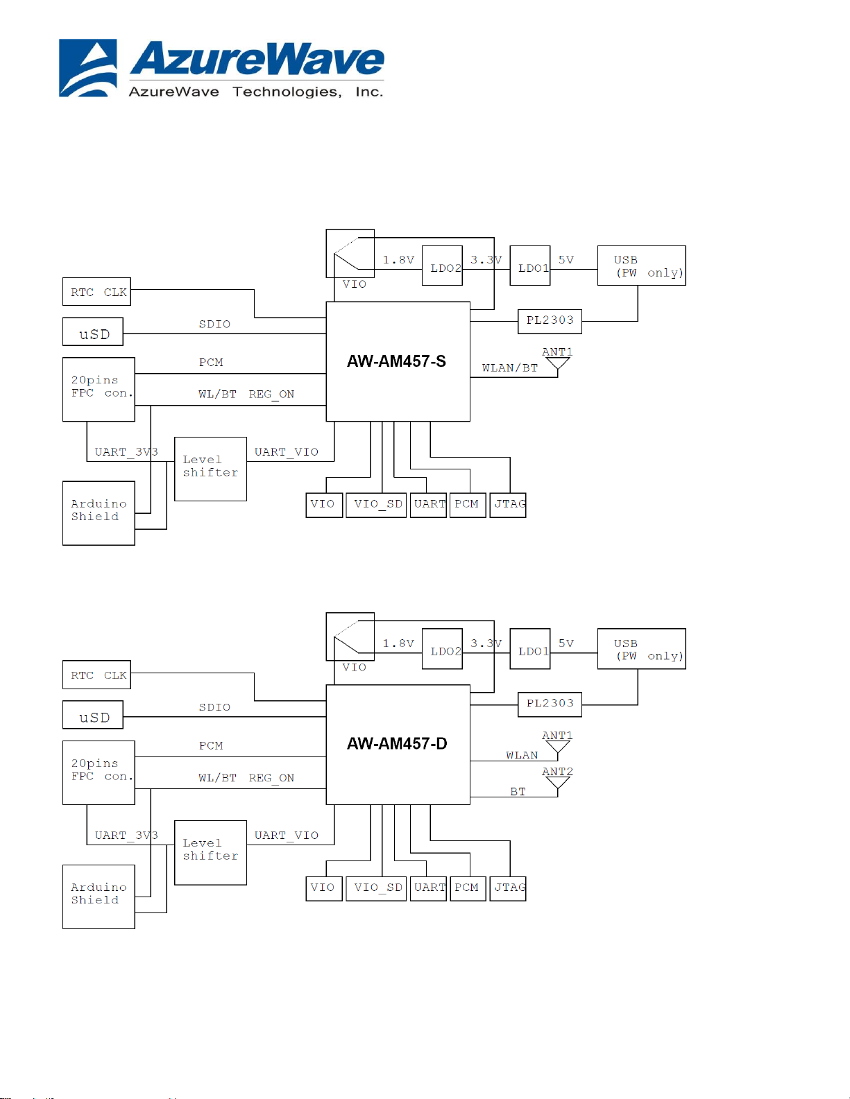
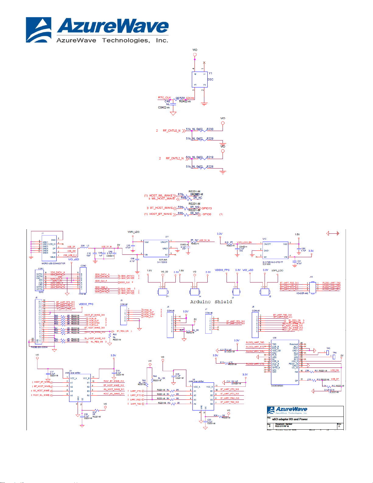
AzureWave provides uSD-15x15 adapter board with Wi-Fi/BT module solutions for NXP i.MX RT
and i.MX 6/7/8 Evaluation Kits. The uSD-15x15 adapter board supportsAW-AM457-S and AW-
AM457-D (w/ NXP W8978, Wi-Fi + BT solutions).
Wi-Fi through uSD interface
BT through UART interface
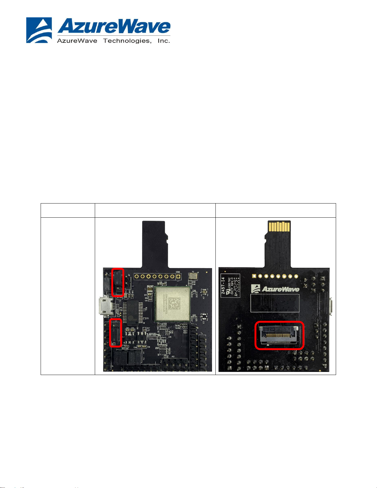
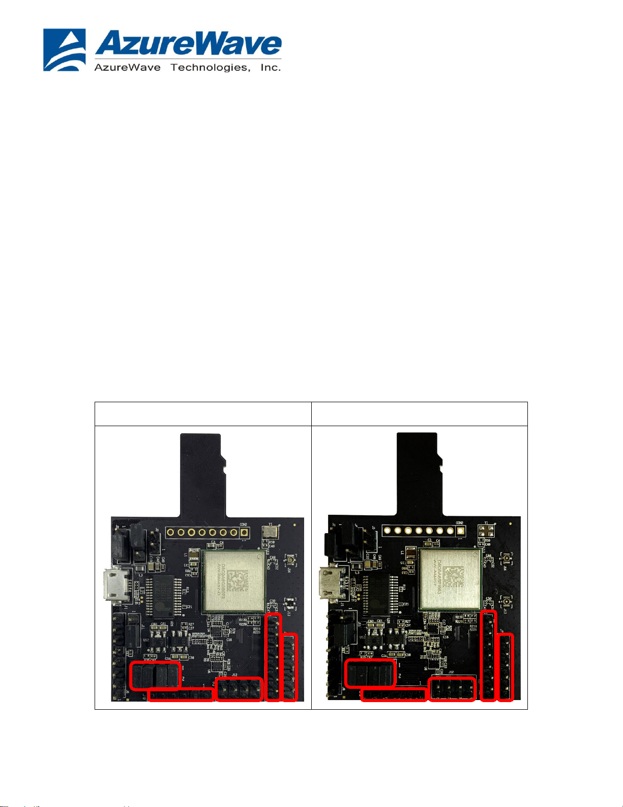
1.1 Supported I/O to host
Micro-SD (uSD) interface for Wi-Fi.
Arduino headers for Bluetooth through UART interface.
FFC connector for UART, PCM, and other control signal.
Embedded UART-to-USB IC as an option for UART.
Other debug and power interface.
1.2 Supported I/O signal level
1.3 Supported RF standards
*Connecting with i-pex gen 4 RF connector