5
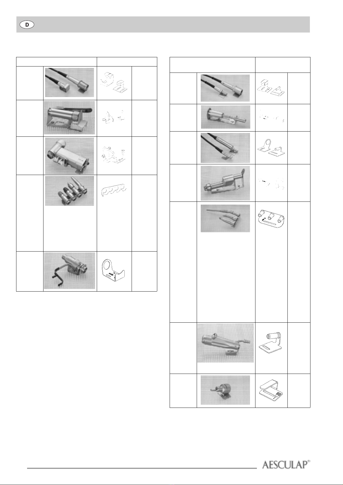
Lagerungssystem für maschinelle Motorenaufbereitung
2. Inhaltsverzeichnis
1. Übersicht der maschinell reinigbaren Maschinen und Zubehör. .2
2. Inhaltsverzeichnis . . . . . . . . . . . . . . . . . . . . . . . . . . . . . . . . . . . . . .5
3. Verwendungszweck . . . . . . . . . . . . . . . . . . . . . . . . . . . . . . . . . . . . .5
4. Funktionsweise. . . . . . . . . . . . . . . . . . . . . . . . . . . . . . . . . . . . . . . . .6
5. Bereitstellung. . . . . . . . . . . . . . . . . . . . . . . . . . . . . . . . . . . . . . . . . .6
6. Montage der Lagerungen . . . . . . . . . . . . . . . . . . . . . . . . . . . . . . . .7
7. Vorbereiten der Komponenten zur maschinellen Aufbereitung. .8
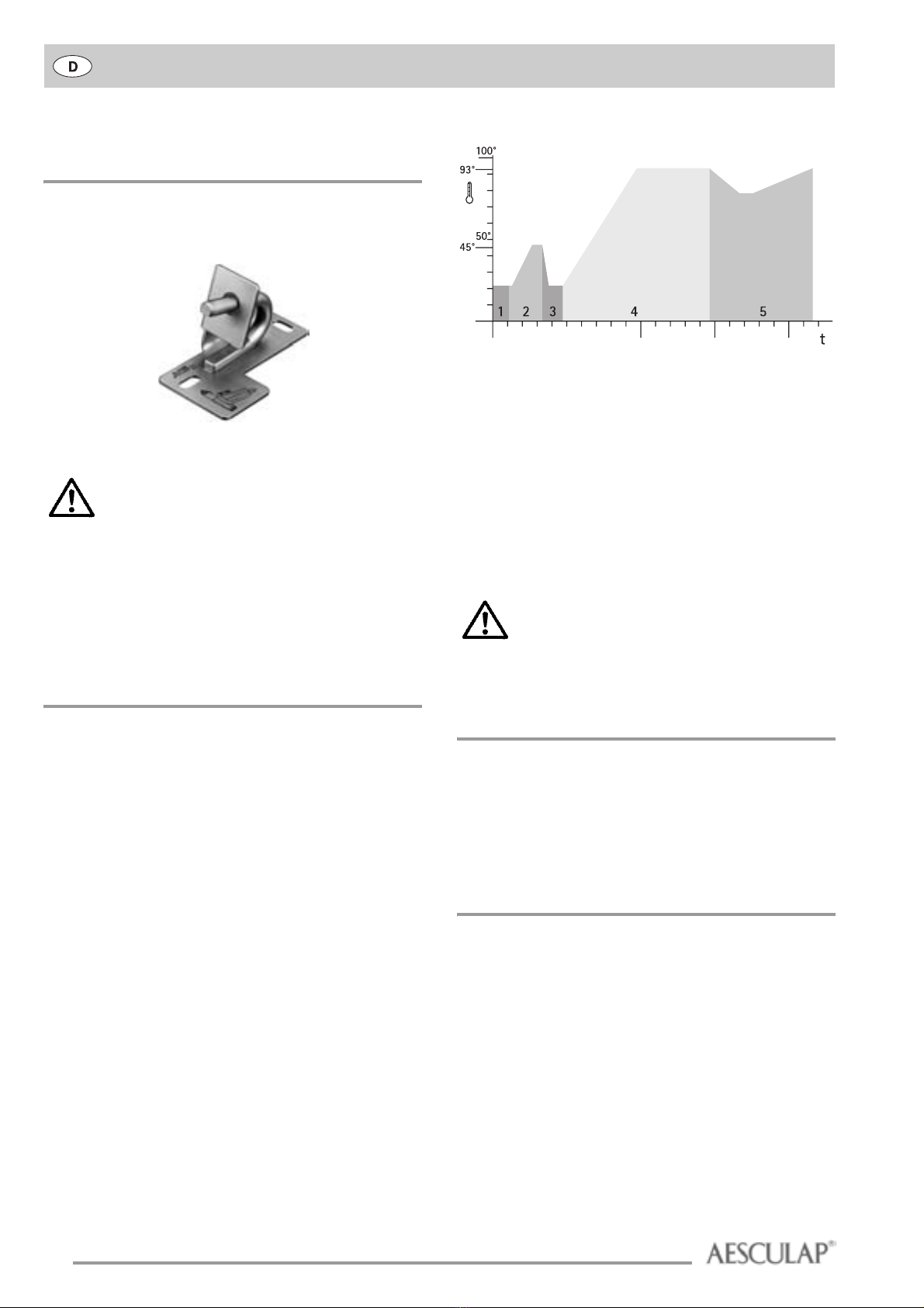
8. Reinigungsprogramm. . . . . . . . . . . . . . . . . . . . . . . . . . . . . . . . . . . .8
9. Pflege . . . . . . . . . . . . . . . . . . . . . . . . . . . . . . . . . . . . . . . . . . . . . . . .8
10. Sterilisation . . . . . . . . . . . . . . . . . . . . . . . . . . . . . . . . . . . . . . . . . . .8
11. Zubehör/Ersatzteile . . . . . . . . . . . . . . . . . . . . . . . . . . . . . . . . . . . . .9
12. Kreislauf bei der maschinellen Aufbereitung. . . . . . . . . . . . . . . . .9
13. Beispiele für Lagerungssets. . . . . . . . . . . . . . . . . . . . . . . . . . . . . . .9
3. Verwendungszweck
Die Lagerungen ermöglichen die maschinelle Reinigung, Desinfektion und
Sterilisation der Aesculap-COMFORT-Motorline, der ACCULAN-II-Serie,
des HiLAN-Motoren-Systems, der MiniLine und ausgewählter INTRA-
Motorenkomponenten.
Abb. 1
GB 221,
GB 222,
GB 223,
GB 224,
GB 225,
GB 226,
GB 227
GB 687 R
ØLesen Sie bitte vor der ersten maschinellen Aufbe-
reitung der Aesculap-Komponenten diese Ge-
brauchsanweisung sorgfältig durch. Sie vermeiden
dadurch Schäden, die durch unsachgemäßen Aufbau
oder Betrieb verursacht und damit nicht von der Ga-
rantie und Haftung abgedeckt werden.
ØDie maschinelle Reinigung der Aesculap-Komponen-
ten darf nur von qualifizierten Personen durchge-
führt werden.
ØWir behalten uns vor, Ausführungen und technische
Daten ohne vorherige Ankündigung zu ändern.
ØDie Aesculap-Komponenten dürfen nur maschinell
gereinigt werden, wenn die Vorgaben, die in dieser
Gebrauchsanweisung beschrieben sind, beachtet
werden. Bei Nichtbeachten der Vorgaben können die
Komponenten beschädigt werden. Außerdem erlischt
die Garantie der Teile.
Motorenkomponenten mit INTRA-
Kupplung Zugehörige Lagerung
ØVerwenden Sie nur ein Reinigungs- und Desinfekti-
onsprogramm wie unter Kapitel 8 beschrieben. Bei
Verwendung ungeeigneter Programme und Reini-
gungsmittel können die Komponenten beschädigt
werden.
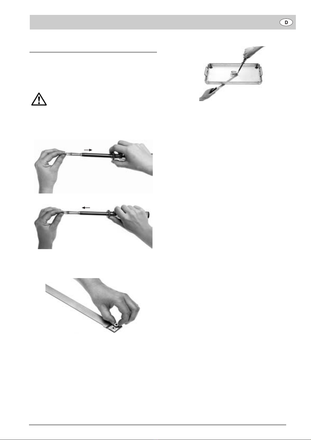
ØBeachten Sie, dass die Druckluftschläuche GA 460,
GA 464, GA 466, GA 505, GA 513 und GA 523 nur
maschinell gereinigt werden dürfen, wenn die Hül-
sen der Steckerseite mit Auslaufbohrungen versehen
sind (siehe Abb. 1). Druckluftschläuche ohne Aus-
laufbohrungen können Sie beim Technischen Service
von Aesculap umarbeiten lassen.
ØDie Biegewellen GB 400 und GB 401 sind erst ab der
Serien-Nr. 0200 maschinell zu reinigen. Biegewellen
mit älteren Seriennummern können Sie beim Tech-
nischen Service von Aesculap umarbeiten lassen.
ØDie ACCULAN-Bohrmaschine GA 620 darf nicht ma-
schinell gereinigt werden. Sie können diese aber
beim Technischen Service von Aesculap nachrüsten
lassen.