B.M. Tecnologie Industriali TTFM100-NG Series User manual

Mod.BM43
COM
Vers.1.0
16/11/2005
Page 1 of
110
ULTRASONIC TRANSIT TIME FLOWMETER
TTFM100-F18-NG
STATIONARY TYPE
INSTRUCTION MANUAL
Rev. 2.0

Mod.BM43
COM
Vers.1.0
16/11/2005
Page 2 of
110
1WORKING PRINCIPLE ......................................................................................................................................4
1.1 TYPICAL USE ..................................................................................................................................................5
1.2 PACKING LIST ................................................................................................................................................6
1.2.2
Connections
...............................................................................................................................................9
2INSTALLATION AND OPERATION...............................................................................................................11
2.1 MEASURING POINT.....................................................................................................................................11
2.2 REQUIRED INFORMATION .........................................................................................................................12
2.3 APRACTICAL EXAMPLE OF RAPID SETTINGS .........................................................................................13
2.3.1
Fluid & pipe’s features
...........................................................................................................................13
2.3.2
Data entry
................................................................................................................................................13
2.4 INSTRUCTIONS FOR CLAMP-ON SENSORS INSTALLATION..................................................................20
2.5 TRANSDUCERS MOUNTING METHODS ....................................................................................................29
2.5.1
Mounting Analysis
...................................................................................................................................36
2.5.2
Signal strength and quality M90
...........................................................................................................36
2.5.3
Total spreading time, time difference M93
.........................................................................................36
2.5.4
Relation between calculated and measured transit time
..................................................................37
3DISPLAY WINDOWS ........................................................................................................................................38
3.1 FLOW RATE- TOTALIZERS MENU..............................................................................................................38
3.2 INITIAL SETTING MENU.............................................................................................................................38
3.3 FLOWRATE UNITS MENU ...........................................................................................................................39
3.4 OPTIONAL SETTING MENU ........................................................................................................................39
3.5 INPUTS/ OUTPUTS MENU ..........................................................................................................................39
3.6 DIAGNOSTICS MENU ..................................................................................................................................41
3.7 OTHER DISPLAY MENU...............................................................................................................................41
3.8 FLOW RATE -TOTALIZERS MENU ANALYSIS ..........................................................................................41
3.9 INITIAL SETTINGS MENU ANALYSIS ........................................................................................................43
3.10 FLOWRATE UNITS MENU ANALYSIS.........................................................................................................50
3.10.1
Inputs/ Outputs Menu Analysis
........................................................................................................56
3.11 DIAGNOSTICS MENU ANALYSIS................................................................................................................73
3.12 OTHER DISPLAYS MENU ANALYSIS ..........................................................................................................74
4DIAGNOSTICS AND PROBLEM SOLVING..................................................................................................76
4.1 AUTOTEST DURING SWITCH ON AND POSSIBLE SOLUTIONS .............................................................76
4.2 ERROR CODES, CAUSES AND SOLUTIONS DURING FUNCTIONING ....................................................76
5APPENDIX 1........................................................................................................................................................77
5.1 SOUND SPEEDS IN SOLIDS........................................................................................................................77
5.2 SOUNDSPEEDS IN FLUIDS ........................................................................................................................80
5.3 SOUND SPEEDS IN WATER AT DEFINITE TEMPERATURES...................................................................94
5.4 PIPE SIZE DATA ...........................................................................................................................................96
6. APPENDIX 2 –MODBUS PROTOCOL ........................................................................................................100

Mod.BM43
COM
Vers.1.0
16/11/2005
Page 3 of
110
IMPORTANT NOTICE!
EACH DEVICE HAS TO BE CONNECTED TO THE SENSORS WITH THE SAME
SERIAL NUMBER OF THE DEVICE.
THE SERIAL NUMBER IS WRITTEN ON THE ID LABEL OF THE DEVICE AND
SENSORS.
INTRODUCTION
Thanks for buying an Ultrasonic Transit Time Flow meter TTFM100-NG series.
The device measures flow rate by calculating the spreading time of an ultrasonic wave in a
liquid, going upstream and downstream into a pipe. This flow meter is mostly used to
measure the flow rate of homogeneous fluids, with a very little percentage of suspended
solids and possibly without gas bubbles.
Its peculiar installation makes these devices suitable for measuring aggressive fluids
(acids, basic and dissolvent) or very soiling fluids (oil and fuels).
The measuring system is composed of a couple of ultrasonic transducers acoustically
coupled to the external pipe’s wall (it is also possible to use transducers in direct contact
with fluid to be measured) and a HOST unit elaborating the sent and received signals from
the transducers. The HOST unit has a DSP microprocessor; it gives signals to interfacing
with the process or the control systems.
Mod.BM43
COM
Vers.1.0
16/11/2005
Page 4 of
110
1WORKING PRINCIPLE
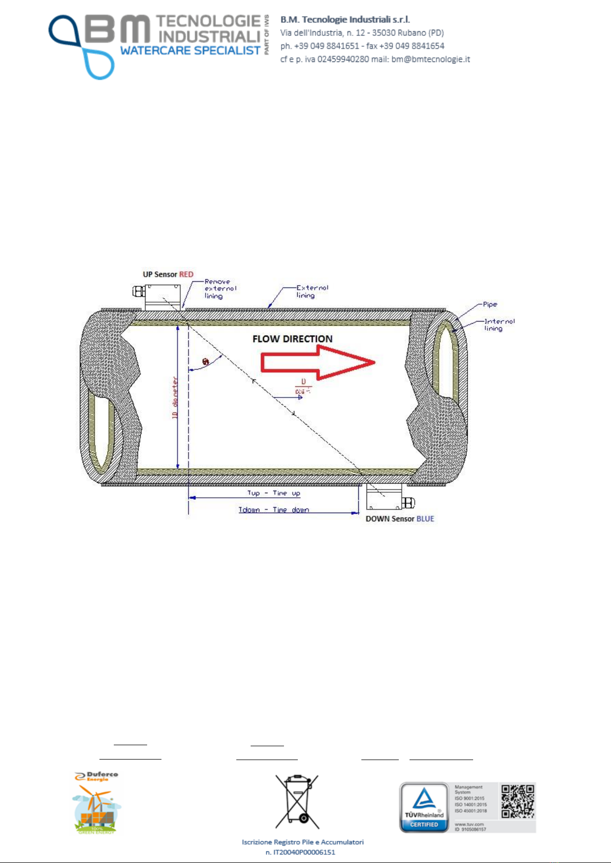
When the ultrasonic wave spreads in a liquid, the flow will cause a changing in the
spreading time depending on downstream or upstream current.
The ultrasonic wave going towards the same directions of the flow increases the spreading
speed, while the ultrasonic wave going towards the opposite side of the flow decreases
the spreading speed.
If the difference between the two spreading times is accurately measured, it would be
possible to calculate the flow speed (see the following picture).
The measures are taken by 2 sensors in direct contact with the pipe’s external surface.
The UP sensor (RED) is placed on the upper side of the pipe’s external surface, the DOWN
sensor (BLUE) is placed on the lower side of the pipe’s external surface.
The sensors positions could look like a “Z” or like a “V” or a “W”, if the pipe has a small
diameter (in the previous sketch, the sensors are “Z” mounted).
The sensors are alternatively used to receive the ultrasonic pulses sent through the way
pipe - fluid - pipe.
The difference between the transmitted and received signals upstream and downstream is
calculated as follows:
(1) (2) (3)
+
=VSINCoCOSDM
Tup
−
=VSINCoCOSDM
Tdown
TdownTup T
SIN DM
V*
*
2
*
=

Mod.BM43
COM
Vers.1.0
16/11/2005
Page 5 of
110
Typical timing signal
T1Downstream time
T2Upstream time
DT = T2-T1
Where:
M Spreading time
D Pipe’s internal diameter
ӨTransmission angle
Co Sound spread speed through the fluid in static conditions
Tup Positive spreading time
Tdown Negative spreading time
V Flow Velocity
The DT value is the difference of the spreading time into a homogenous fluid without gas
bubbles.
The equation (3) for calculating the average speed “V” could be used for all the types of
fluids in ideal conditions. The fluid speed measuring is in fact conditioned by different
factors which make the precision decrease: for example the dumps on the pipe are
internal walls: they change the measuring principle of the transit time flow meter.
TTFM100 series has are a lot of solutions trying to solve these problems, compensating
the temperature influence, the dumped internal walls and the asymmetry in the speed
distribution, in order to measure in critical conditions too.
It is possible to adjust the zero point of the device: if the fluid is in static conditions, this
operation makes the repeatability precision increase until reaching values near to 0.5%.
1.1
TYPICAL USE
•Water treatment, slurry and process water pumping;
•Oil and chemical industries;
•Hydro-electric, cooling, anti-fire stations;
•Extraction industries;
•Food, paper and pharmaceutical industries;
•Car industries;
•Flow balancing;

Mod.BM43
COM
Vers.1.0
16/11/2005
Page 6 of
110
•Heat measuring in central systems.
1.2
PACKING LIST
•Ultrasonic Transit Time Flow meter TTFM100-F18-NG 1pcs
•
Standard Clamp-on sensors TS2 2pcs
•
Standard Clamp-on sensors TM1 2pcs
•
Standard Clamp-on sensors TL1 2pcs
•Acoustic coupling gel 1pcs
•Sensors mounting kit (optional) 1pcs
•Quality certification 1pcs
•Test Certificate 1 copy
•Instruction Manual 1pcs
*DEPENDING FROM THE TYPE OF SENSORS ORDERED BY THE CUSTOMER.
TECHNICAL FEATURES
ITEM
PERFORMANCE
PIPE
Material
Internal Diameter
Pipe length
Steel, Stainless Steel, cast iron, plastic, with
smooth walls, with rough walls, with very thin
walls.
15 ~ 6000 mm.
Upstream: bigger than 10D and 30D far from
the pump, downstream: bigger than 5D.
FLUID
Type
Turbidity
Temperature
Potable water, sea water, other liquids with
few suspended solids.
Smaller than 10000ppm (mg/l) with a few air
bubbles.
-30°C ~ +90°C, without ice at low
temperatures.
SPEED
Speed
-16 m/s ~ +16 m/s
SENSORS
Type
0. Standard –TS2 DN15…..DN100 mm

Mod.BM43
COM
Vers.1.0
16/11/2005
Page 7 of
110
Cable lengths
1. Standard –TM1 DN50…..DN1000 mm
2. Standard –TL1 DN300…DN6000 mm
Temp. Range: -30°…+90°C
3. High Temperature TTS100-S1-NG-HT
DN15-150mm
4. High Temperature TTS100-M1-NG-HT
DN50-700mm
Temp. Range: -30…+160°C
5. Insertion type B > 50 mm < 2000 mm for
under charge applications. Min. temp. -20°C,
max temp. 160°C, max pressure 60 bars.
4. Sensors pre-mounted between flanges
BNG type from DN50 to DN1000, PN16 until
DN400, PN10 until DN1000, min. temp.
-40°C, max. Temp. 160°C.
Min. 5 m, max. 200 m.
SENSORS
Mounting methods
“V” Method: for pipes with small diameter,
until DN400 mm.
“Z” Method: for pipes with big diameters,
bigger than DN250.
“W” or “N” Method: suitable for very small
pipes, DN15….100.
FLOWMETER
Display & Keypad
Mounting
Input
Outputs
Dimensions
Alphanumeric 2 x 20 digits LCD back lighted.
DIN Rail Mounting.
5 current loop 4 - 20 mA, 0.1% accuracy.
Selection 4 - 20 mA or 0 - 20 mA current
loop, 0.1% accuracy.
Serial port RS485.
Programmable output frequency: 12…9999
Hz.
Output relays 1A/125VAC or 2A/30VDC for
volume pulses or alarms.
90 x 90 x 36 mm.
ENVIRONMENTAL
AND OPERATIONG
CONDITIONS
Temperature
Humidity
Device: -20°C…+40°C
Sensors: -20°C…+80°C
Device: 85% RH (40°C)
Sensors: 98% RH (40°C), possible
functioning in water less deep than 2 m.
MEASURING ACCURACY
+/- 1% (after calibration)

Mod.BM43
COM
Vers.1.0
16/11/2005
Page 8 of
110
Repeatability: +/-0.2%...0.5% at
0.6…16mt/s
Linearity: 0.5%
Min measuring cycle: 500 milliseconds
POWER SUPPLY
12…36VDC - 0,12A
Attention!: Negative connector common with
negative 0/4-20 mA output.
FUNCTIONING
Continuous
1.2.1 Wiring

Mod.BM43
COM
Vers.1.0
16/11/2005
Page 9 of
110
1.2.2
Connections
The kind of connection and the number of connections, both depend from the application
the flow meter is used for.

Mod.BM43
COM
Vers.1.0
16/11/2005
Page 10 of
110
The minimum necessary connections are:
•Electrical supply 12..36 VDC
•Ultrasonic UP and Down sensors
Warning!!!!!
The sensors must be connected to their clamps only after having momentarily short
circuited the white and brown cables in order to download the electrostatic fields
generated during the sensors movement.
The crystal inside the transducer acts as a converter and turns mechanical energy into
electrical during the mounting process.
When the sensors are connected to the clamp-house, the electrostatic fields into the
capacitor could damage seriously the measuring circuit of the device.
•4-20 ma output and/or frequency and/or pulses signals
•Temperature measure for calorimeter
•RS485 connection for data saving.

Mod.BM43
COM
Vers.1.0
16/11/2005
Page 11 of
110
2INSTALLATION AND OPERATION
The ultrasonic flow meter mounting is a quite simple method. It is only necessary to
determine the mounting point in the pipe and knowing some information about the pipe’s
dimension.
2.1
MEASURING POINT
It is very important to select the right measuring point. The fluid has to be a measurable
one and the pipe should be indicated among the ones that are suitable for this technology.
Please do not hesitate to contact B.M. TECNOLOGIE INDUSTRIALI for any further
clarification.
Please proceed as follows:
1) Select the measuring point on the pipe, in order to have a turbulence-free fluid.
2) The distance of the measurement point upstream should be 10D, downstream 5D.
If there are pumps or valves in the upstream part of the pipe, it is suggested to
increase the distance up to 30 D.
3) Actually, the device could be installed in pipes with lining, but it is suggested to
install insertion sensors and no clamp-on sensors, above all if the pipe is old or
damaged.
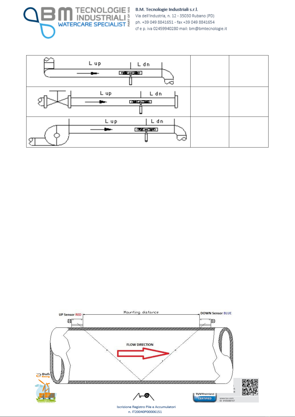
Possibile pipes configuration & possibile transducers position
Upstream
Dimensions
Downstream
Dimensions
L up x
Diameters
L dn x
Diameters
10D
5D
10D
5D
10D
5D
12D
5D
Mod.BM43
COM
Vers.1.0
16/11/2005
Page 12 of
110
20D
5D
20D
5D
30D
5D
2.2
REQUIRED INFORMATION
1) Pipe’s external diameter without liner.
2) Pipe’s internal diameter or thickness.
3) Pipe’s material or speed of sound through that material.
4) Internal liner (if existing), material or thickness or speed of sound through that
material.
5) Fluid type (or speed of sound through this fluid).
6) Transducers type.
7) Transducer mounting method (V, Z method or W, N for little pipes).
Now, in M25 menu it is be possible to see the right mounting distance between the
transducers.

Mod.BM43
COM
Vers.1.0
16/11/2005
Page 13 of
110
2.3 A PRACTICAL EXAMPLE OF RAPID SETTINGS
The following example shows an application with a DN 400 carbon steel pipe, no liner,
with “V” mounted sensors.
IMPORTANT NOTICE:
WHEN THE SET-UP IS COMPLETED, THE USER MUST GO BACK TO MENU 26 AND
SELECT OPTION 1. SOLIDIFY SETTINGS, AND THEN PRESS ENTER.
IN THIS WAY THE PARAMETERS WILL BE SAVED EVEN IF THE POWER SUPPLY
GOES OFF.
2.3.1
Fluid & pipe’s features
This is a zinc pipe, so its thickness is not a problem. It is also important to measure the
pipe’s circumference: it should be 1286 mm. The pipe is PN10 and it will measure potable
water.
2.3.2
Data entry
ATTENTION! The XXXXX values indicated in the following windows are only
examples. The value could vary and must not be taken as representative.
TTFM100-F18-NG –how access to menu items using the 4 keys
The MENU items are the same of all the TTFM series meters; the only difference is the
way to access them.
•Example:
We want to change the “Pipe Outer Perimeter” - MENU 10.

Mod.BM43
COM
Vers.1.0
16/11/2005
Page 14 of
110
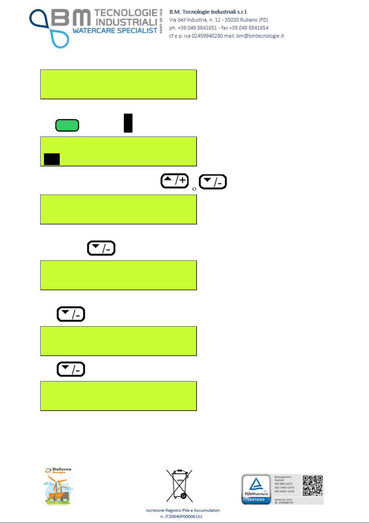
Simply press the key and the display will be, for example:
F l o w 0 , 0 0 0 0 m 3 / h *R
W i n d o w N o . =
The unit is waiting your input, by pressing the key, the first digit after equal
sign (=) will be
F l o w 0 , 0 0 0 0 m 3 / h *R
W i n d o w N o . =1
Now, pressing the key the display will be:
F l o w 0 , 0 0 0 0 m 3 / h *R
W i n d o w N o . =10
By pressing the key we will access MENU 10, Pipe Outer Perimeter:
P i p e O u t e r P e r i m e t e r
x x x x . x x x m m
Now we want to enter 725 mm to set up our application:
Press the key and the display will show:
P i p e O u t e r P e r i m e t e r
> _ mm
Using the and keys you can change the display value.
Press 7 times and the unit will display:
P i p e O u t e r P e r i m e t e r
> 7_ mm
Press 1 time and the unit will display:

Mod.BM43
COM
Vers.1.0
16/11/2005
Page 15 of
110
P i p e O u t e r P e r i m e t e r
> 70_ mm
Press 2 times:
P i p e O u t e r P e r i m e t e r
> 72_ mm
Press 1 time and the unit will display:
P i p e O u t e r P e r i m e t e r
> 720_ mm
Press 5 times:
P i p e O u t e r P e r i m e t e r
> 725_ mm
Than press , now the unit will display:
P i p e O u t e r P e r i m e t e r
725 mm
Using the keys it’s possible to enter all
the digits you need to program the TTFM100-F18-NG.
The and keys are used to scroll the menu up or down.

Mod.BM43
COM
Vers.1.0
16/11/2005
Page 16 of
110
A practical Example:
Switch on the device and it will display:
V e r . XX.XX
S / N = X X X X X X X X
Then it will display, (it depends from the last switch off) for example:
F l o w 0 . 0 0 0 0 m 3 / h *I
N o S i g n a l D e t e c t e d
The transducers are not installed and their mounting distance will be displayed only after
the set-up. Actually the device detects no signals.
Press
MENU
and the device will display:
F l o w 0 . 0 0 0 0 m 3 / h *I
W i n d o w N o . =
Press
1
0
and the device will display window no. 10.
P i p e O ut e r P e r im e t e r
X X X X m m
Press
1
2
8
6
and
ENT
:

Mod.BM43
COM
Vers.1.0
16/11/2005
Page 17 of
110
P i p e O ut e r P er i m e t e r
1 2 8 6 m m
If you press a wrong digit, press to correct.
Press and the device will display:
P i p e O u t e r D i a m e t e r
XXX.XXX mm
Press and the device will display:
P i p e W a l l T h i c k n e s s
X . X m m
Press
6
,
.
,
5
+
ENT
and the it will display:
P i p e W a l l T h i c k n e s s
6 . 5 m m
Press and the device will display:
P i p e I n n e r D i a m e t e r
3 9 6 . 34 7 m m
The device calculates the value based on the entered settings.
It is possible to press again and the device will display the parameters it
calculated until now.
Press and the device will display:
Mod.BM43
COM
Vers.1.0
16/11/2005
Page 18 of
110
P i p e M a t e r i a l [ 1 4
1. S t a i n l e s s S t e e l
The pipe material depends from the material of the pipe.
Press
ENT
and “1” and is blinking.
P i p e M a t e r i a l [ 1 4
>1 . S t a i n l e s s S t e e l
Select the right material by using the
P i p e M a t e r i a l [ 1 4
> 0 . C a r b o n S t e e l
Press ENT and and the device will display:
L i n e r M a t e r i a l [ 1 6
0 . N o n e , N o L i n e r
In this case, the pipe has no internal lining, so “0” is correct.
Press and the device will display:
F l u i d T y p e [ 2 0
0. W a t e r ( G e n e r a l )
Press and the device will display:
T r a n s d u c e r T y p e [ 2 3
16. C l a m p - o n T M1
NOTE:
The standard sensors are Clamp-on TM1 type, for pipes from DN50 up to
DN1000.
It is possible to ask for different sensors, depending from the application.

Mod.BM43
COM
Vers.1.0
16/11/2005
Page 19 of
110
Press and the device will display:
T r a n s d u c e r M o u n t i n g
0. V
Press and the device will display:
T r a n s d u c e r S p a c i n g
3 8 5 . 26 8 m m
The displayed value id the sensors mounting distance, as shown in par. 2.2.
It is possible to install the transducers, as shown in the following par. 2.4.
Press and the device will display:
D e f a u l t s e t t i n g s [ 2 6
1 . S o l i d i f y s e t t i n g s
Press and the device will display:
S a v e / L o a d p a r a m e t e r s
>>
Press to go through the parameters:
S a v e / L o a d p a r a m e t e r s
>> T o B r o w s e
Press and the device will display:
S a v e / L o a d p a r a m e t e r s
0: 4 0 9 , 34 7 m m , C a rb o n
This setting refers to the example configuration: DN400 carbon steel pipe.

Mod.BM43
COM
Vers.1.0
16/11/2005
Page 20 of
110
Press and the device will display:
S a v e / L o a d p a r a m e t e r s
E n t r y t o S A V E
Press MENU, 1, ENT and the device will display:
F l o w 0 . 0 0 0 0 m 3 / h *I
N o S i g n a l D e t e c t e d
Now it is possible to install the transducers.
2.4 INSTRUCTIONS FOR CLAMP-ON SENSORS INSTALLATION
If you ordered Clamp-on sensors type TTS100-TS2-NG, TTS100-M1-NG,
TTS100-L1-NG,TTS100-S1-NG-HT, TTS100-M1-NG-HT the following instructions
are very important for a correct installation of the sensors:
1. In order to install the sensors, check if the pipe has features which could affect the
measure, i.e. rust, dirt…
This manual suits for next models
1
Table of contents
Other B.M. Tecnologie Industriali Measuring Instrument manuals

Popular Measuring Instrument manuals by other brands


Endress+Hauser
Endress+Hauser Tankvision Multi Scan NXA83 operating instructions

Kurth Electronic
Kurth Electronic KE8000 operating manual

Fluke Calibration
Fluke Calibration 525B user manual

Blaupunkt
Blaupunkt TPMS 3.0 Operating and installation instructions

TSI Instruments
TSI Instruments SidePak AM520 user guide

Toshiba
Toshiba LF232 product manual


