B.M. Tecnologie Industriali TTFM100B-HH-NG User manual

Mod.BM43
COM
Vers.1.0
16/11/2005
Page 1 of
95
B.M. Tecnologie Industriali
Via Praimbole 13
35010 LIMENA (PD)
VAT No. IT02459940280
Tel. +39 (0) 49 884.16.51
Fax +39 (0) 49 884.16.54
E-Mail [email protected]
Web www.bmtecnologie.it
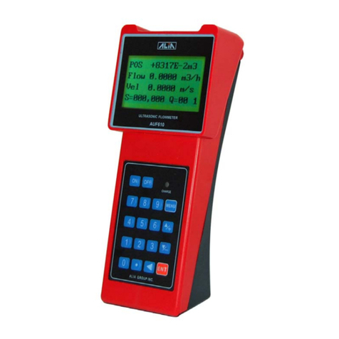
ULTRASONIC TRANSIT TIME FLOWMETER
TTFM100B-HH-NG
HAND-HELD TYPE
INSTRUCTION MANUAL – REV. 2.3.1

Mod.BM43
COM
Vers.1.0
16/11/2005
Page 2 of
95
B.M. Tecnologie Industriali
Via Praimbole 13
35010 LIMENA (PD)
VAT No. IT02459940280
Tel. +39 (0) 49 884.16.51
Fax +39 (0) 49 884.16.54
E-Mail [email protected]
Web www.bmtecnologie.it
INTRODUCTION 5
1. WORKING PRINCIPLE 6
1.1 TYPICAL USE 7
1.2 DESCRIPTION 8
1.3 PACKING LIST 8
1.4 INTEGRATED REAL TIME CLOCK (RTC) 9
1.5 PRODCUT ID 9
1.6 TECHNICAL FEATURES 9
2. INSTALLATION AND OPERATION 10
2.1 MEASURING POINT 10
2.2 REQUIRED CONDITIONS 11
2.3 A PRACTICAL EXAMPLE OF RAPID SETTINGS 12
2.3.1 FLUID AND PIPE’S FEATURES 12
2.3.2 DATA ENTRY 12
2.4 INSTRUCTIONS FOR CLAMP-ON SENSORS MOUNTING 17
2.5 TRANSDUCERS MOUNTING METHODS 25
2.5.1 “V” MOUNTING METHOD 27
2.5.2 “Z” MOUNTING METHOD 28
2.5.3 “W” and “N” MOUNTING METHODS 30
2.6 MOUNTING ANALYSIS 31
2.6.1 SIGNAL’S STREANGTH & QUALITY 31
2.6.2 TOTAL SPREADING TIME, TIME DIFFERENCE M93 32
2.6.3 RELATION BETWEEN CALCULATED AND MEASURED TRANSIT TIME
32
3. DISPLAY WINDOWS 33
3.1 FLOWRATE- TOTALIZERS MENU 33
3.2 INITIAL SETTINGS MENU 33
3.3 FLOWRATE UNITS MENU 34
3.4 OPTIONAL SETTING MENU 34
3.5 INPUTS/OUTPUTS MENU 34
3.6 DIAGNOSTICS MENU 35
3.7 OTHER DISPLAYS MENU 35
3.8 FLOWRATE- TOTALIZERS MENU ANALYSIS 36
3.9 INITIAL SETTING MENU ANALYSIS 39
3.10 FLOWRATE UNITS MENU ANALYSIS 46

Mod.BM43
COM
Vers.1.0
16/11/2005
Page 3 of
95
B.M. Tecnologie Industriali
Via Praimbole 13
35010 LIMENA (PD)
VAT No. IT02459940280
Tel. +39 (0) 49 884.16.51
Fax +39 (0) 49 884.16.54
E-Mail [email protected]
Web www.bmtecnologie.it
3.11 INPUTS/OUTPUTS MENU NALYSIS 52
3.12 DIAGNOSTICS MENU ANALYSIS 61
3.13 OTHER DISPLAYS MENU ANALYSIS 62
4. DIAGNOSTICS AND PROBLEM SOLVING 64
4.1 AUTOTEST DURING SWITCHING ON AND POSSIBLE SOLUTIONS 64
4.2 ERROR CODES, CAUSES AND SOLUTIONS DURING FUNCTIONING 64
4.3 OTHER PROBLEMS & SOLUTIONS 65
5. COMMUNICATION WITH A PC AND/ OR DATA LOGGING 66
5.1 REQUIRED HARDWARE 66
5.2 COMPLETE PI-OUT OF DB9 M DOOR 66
5.3 DIRECT CONTROL – COMMUNICATION PROTOCOL 67
5.4 USE OF THE PREFIX IN THE CONTROL 68
5.5 KEYPAD CODES 69
6. APPENDIX 70
6.1 SOUNS SPEEDS IN SOLIDS 70
6.2 SOUND SPEEDS IN FLUIDS 72
6.3 SOUND SPEEDS IN WATER AT SELECTED TEMPERATURES 86
6.4 PIPE SIZE DATA 88
7. EC- DECLARATION OF CONFORMITY 93

Mod.BM43
COM
Vers.1.0
16/11/2005
Page 4 of
95
B.M. Tecnologie Industriali
Via Praimbole 13
35010 LIMENA (PD)
VAT No. IT02459940280
Tel. +39 (0) 49 884.16.51
Fax +39 (0) 49 884.16.54
E-Mail [email protected]
Web www.bmtecnologie.it
IMPORTANT NOTICES:
1. EACH UNIT MUST BE CONNECTED TO ITS
OWN SENSORS.
THE SERIAL NUMBERS OF SENSORS AND
UNITS ARE WRITTEN IN THE ID LABELS
AND MUST CORRESPOND EACH OTHER.
2. THE DEVICE IS SUPPLIED WITH
UNCHARGED BATTERIES.
PLS CHARGE THE BATTERIES FOR 12
HOURS BEFORE USING THE DEVICE.

Mod.BM43
COM
Vers.1.0
16/11/2005
Page 5 of
95
B.M. Tecnologie Industriali
Via Praimbole 13
35010 LIMENA (PD)
VAT No. IT02459940280
Tel. +39 (0) 49 884.16.51
Fax +39 (0) 49 884.16.54
E-Mail [email protected]
Web www.bmtecnologie.it
INTRODUCTION
Thanks for buying an Ultrasonic Transit Time Flowmeter TTFM100-NG series.
The device measures flowrate by calculating the spreading time of an ultrasonic wave in a
liquid, going upstream and downstream into a pipe. This flowmeter is mostly used to
measured the flowrate of homogeneous fluids , with a very little percentage of suspended
solids and possibly without gas bubbles.
Its peculiar installation makes this devices suitable for measuring aggressive fluids (acids,
basic and dissolvents) or very soiling fluids(oil and fuels).
The measuring system is composed of a couple of ultrasonic transducers acoustically
coupled to the external pipe’s wall (it is also possible to use transducers in direct contact
with fluid to be measured) and a HOST unit elaborating the sent and received signals from
the transducers. The HOST unit has a DSP microprocessor, it gives signals to interfacing
with the process or the control systems.
The devices main features are:
•Clamp-on sensors: it is not necessary to stop the flow to install them.
•AC and DC supply: 230 VAC.
•The time difference during the measuring process could be 0.2 ns.
•RS232 output.
•All the measures could be driven to the RS232 in order to save data into a PC or a
serial printer.

Mod.BM43
COM
Vers.1.0
16/11/2005
Page 6 of
95
B.M. Tecnologie Industriali
Via Praimbole 13
35010 LIMENA (PD)
VAT No. IT02459940280
Tel. +39 (0) 49 884.16.51
Fax +39 (0) 49 884.16.54
E-Mail [email protected]
Web www.bmtecnologie.it
1. WORKING PRINCIPLE
When the ultrasonic wave spreads in a liquid, the flow will cause a changing in the
spreading time depending on downstream or upstream current.
The ultrasonic wave going towards the same directions of the flow increases the spreading
speed, while the ultrasonic wave going towards the opposite side of the flow decreases the
spreading speed.
If the difference between the two spreading times is accurately measured, it would be
possible to calculate the flow speed (see the following picture).
The measures are taken by 2 sensors in direct contact with the pipe’s external surface.
The UP sensor (RED) is placed on the upper side of the pipe’s external surface, the DOWN
sensor (BLUE) is placed on the lower side of the pipe’s external surface.
The sensors positions could look like a “Z” or like a “V” or a “W”, if the pipe has a small
diameter (in the previous sketch, the sensors are “Z” mounted).
The sensors are alternatively used to receive the ultrasonic pulses sent through the way
pipe - fluid - pipe.
The difference between the transmitted and received signals upstream and downstream is
calculated as follows:
(1) (2) (3)
Θ+
Θ
∗
=VSINCoCOSDM
Tup
Θ−
Θ
∗
=VSINCoCOSDM
Tdown
TdownTup T
SIN DM
V*
*
2
*∆
Θ
=

Mod.BM43
COM
Vers.1.0
16/11/2005
Page 7 of
95
B.M. Tecnologie Industriali
Via Praimbole 13
35010 LIMENA (PD)
VAT No. IT02459940280
Tel. +39 (0) 49 884.16.51
Fax +39 (0) 49 884.16.54
E-Mail [email protected]
Web www.bmtecnologie.it
Where:
M Spreading time
D Pipe’s internal diameter
ӨTransmission angle
Co Sound spread speed through the fluid in static conditions
Tup Positive spreading time
Tdown Negative spreading time
V Flow Velocity
The DT value is the difference of the spreading time into a homogenous fluid without gas
bubbles.
The equation (3) for calculating the average speed “V” could be used for all the types of
fluids in ideal conditions. The fluid speed measuring is in fact conditioned by different
factors which make the precision decrease: for example the dumps on the pipe are internal
walls: they change the measuring principle of the transit time flow meter.
TTFM100 series has are a lot of solutions trying to solve these problems, compensating the
temperature influence, the dumped internal walls and the asymmetry in the speed
distribution, in order to measure in critical conditions too.
It is possible to adjust the zero point of the device: if the fluid is in static conditions, this
operation makes the repeatability precision increase until reaching values near to 0.5%.
1.1 TYPICAL USE
•Water treatment, slurry and process water pumping;
•Oil and chemical industries;
•Hydro-electric, cooling, anti-fire stations;
•Extraction industries;
•Food, paper and pharmaceutical industries;
•Car industries;
•Flow balancing;
•Heat measuring in central systems.

Mod.BM43
COM
Vers.1.0
16/11/2005
Page 8 of
95
B.M. Tecnologie Industriali
Via Praimbole 13
35010 LIMENA (PD)
VAT No. IT02459940280
Tel. +39 (0) 49 884.16.51
Fax +39 (0) 49 884.16.54
E-Mail [email protected]
Web www.bmtecnologie.it
1.2 DESCRIPTION
Frontal View
Top View
Bottom View
1.3 PACKING LIST
•Portable ultrasonic transit time flowmeter 1 pc
•Serial cable DB9.F 1 pc
•Battery charger 12 VDC/ 0.5 A 1 pc
•Adaptor for serial connector/ battery charger 1 pc
•
Clamp-on sensors TS2 (small)* 2 pcs
•
Clamp-on sensors TM1 (medium)* 2 pcs
•
Clamp-on sensors TL1 (large)* 2 pcs
•Spiral cable, 5mt (optional 10 mt straight cable) 2 pcs
•Acoustic couplant (grease) 1 pc
•Sensors mounting kit 2 pcs
•EC certification 1 pc
•Instruction Manual 1 pc
* depending from the type of sensors ordered by the customer

Mod.BM43
COM
Vers.1.0
16/11/2005
Page 9 of
95
B.M. Tecnologie Industriali
Via Praimbole 13
35010 LIMENA (PD)
VAT No. IT02459940280
Tel. +39 (0) 49 884.16.51
Fax +39 (0) 49 884.16.54
E-Mail [email protected]
Web www.bmtecnologie.it
1.4 INTEGRATED REAL TIME CLOCK (RTC)
The user’s settings are saved into the device’s memory for at least 2100 years in case of
power failures. The device could be protected by a PASSWORD.
The RTC remains active until the battery discharge tension is 1.5 V.
Ref. to menu M60 for resetting current date and time in the format: yy, mm, dd.
1.5 PRODUCT ID
Each device has a serial number, generated during its production. It could not be changed,
it should be used in case of repair and it could be displayed by menu M61.
1.6 TECHNICAL FEATURES
FEATURE
SPECIFICATION
Linearity
0.5%
Repeatability
0.2%
Accuracy
+/- 1% of the reading value > = 0.2 m/s
Response time
From 0 to 999 seconds, set by the user.
Speed
+/- 32 m/s
Pipes diameter
From DN20 to DN 6000
Eng. Units
Meters, Feet, Cubic meters, Cubic feet, USA
Gallons, Imperial Gallons, USA Million
Gallons, set by the user.
Totalizers
7 digit for positive, negative and net
flowrate.
Measurable liquids All the liquids (virtually)
Safety Possible to set a password for blocking the
device.
Display
Graphic dislya4 lines, 16 characters.
Interface
RS232-C from 75 to 57600 BPS.
Transducers
TS-2, TM-1, TL-1, or High temperature
sensors, at customers request.
Cable lengths From 2 x 5 m up to 2 x 500 m
Supply 3 x AAA Ni-MH batteries (included) for up
to 10 hours of continuous operation
Data logger
Internal data logger to save up to 2000
lines of data.
Manual totalizer 7 digit totalizaer for manual acquisitions
and calibrations.
Housing material
ABS
Housing dimensions
460 (L) x 400 (W) x 110 (H) mm
Total weight
4.5 kg batteries included

Mod.BM43
COM
Vers.1.0
16/11/2005
Page 10 of
95
B.M. Tecnologie Industriali
Via Praimbole 13
35010 LIMENA (PD)
VAT No. IT02459940280
Tel. +39 (0) 49 884.16.51
Fax +39 (0) 49 884.16.54
E-Mail [email protected]
Web www.bmtecnologie.it
2. INSTALLATION AND OPERATION
The installation of TTFM-100-B-HH-NG series is quite simple. It is only necessary to
determine the mounting point in the pipe and knowing some information about the pipe’s
dimension.
2.1 MEASURING POINT
It is very important to select the right measuring point. The fluid has to be a measurable
fluid and the pipe should be suitable for this measuring technology.
Do not hesitate to contact B.M. TECNOLOGIE INDUSTRIALI for any further clarification.
Please proceed as follows:
1) Select the measuring point on the pipe, in order to have a fluid free from
turbulences.
2) The distance of measurement point upstream is 10D, downstream is within 5D. If
there is valve upstream, it is suggested to increase the distance up to 30 D.
3) Actually, the device could be installed into pipes with lining, but it is suggested to
avoid it above all if the pipe is old or damaged. Pipes should be suitable to this
measuring technology in order to improve measure and precision.
Possibile pipes configuration & possibile transducers position
Upstream
Dimensions
Downstream
Dimensions
L up x
Diameters L dn x
Diameters
10D 5D
10D 5D
10D 5D
12D 5D
20D 5D

Mod.BM43
COM
Vers.1.0
16/11/2005
Page 11 of
95
B.M. Tecnologie Industriali
Via Praimbole 13
35010 LIMENA (PD)
VAT No. IT02459940280
Tel. +39 (0) 49 884.16.51
Fax +39 (0) 49 884.16.54
E-Mail [email protected]
Web www.bmtecnologie.it
20D 5D
30D 5D
2.2 REQUIRED CONDITIONS
The more precise the below mentioned information, the better accuracy and measure:
1) Pipe’s external diameter, without liner, if there is a liner.
2) Pipe’s internal diameter or thickness.
3) Pipe’s material or speed of sound through that material.
4) Internal liner: material and thickness or speed of sound through that material.
5) Fluid type or speed of sound through that fluid.
6) Transducers type.
7) Transducers mounting method (V, Z, N, W method).
In M25 menu it is possible to see the right mounting distance between the transducers.

Mod.BM43
COM
Vers.1.0
16/11/2005
Page 12 of
95
B.M. Tecnologie Industriali
Via Praimbole 13
35010 LIMENA (PD)
VAT No. IT02459940280
Tel. +39 (0) 49 884.16.51
Fax +39 (0) 49 884.16.54
E-Mail [email protected]
Web www.bmtecnologie.it
2.3 A PRACTICAL EXAMPLE OF RAPID SETTINGS
The following example shows an application with a DN 400 carbon steel pipe, no liner, with
“V” mounted sensors.
IMPORTANT NOTICE:
WHEN THE SET-UP IS COMPLETED, THE USER MUST GO BACK TO MENU 26 AND
SELECT OPTION 1. SOLIDIFY SETTINGS, AND THEN PRESS ENTER.
IN THIS WAY THE PARAMETERS WILL BE SAVED EVEN IF THE POWER SUPPLY
GOES OFF.
2.3.1 Fluid & pipe’s features
This is a zinc pipe, so its thickness is not a problem. It is also important to measure the
pipe’s circumference: it should be 1286 mm. The pipe is PN10 and it will measure potable
water.
2.3.2
Data Entry
ATTENTION! The XXXXX values in the following windows are only examples.
The value could vary and must not be taken as representative.
Switch on the device and it will display:
Ver.
XX.XX
S/N=XXXXXXXX
Then it will display, (it depends from the last switch off) for example:
Flow 0.0000 m3/h *I
No Signal Detected
The transducers are not installed and their mounting distance will be displayed only after
the set-up. Actually the device detects no signals.
Press and the device will display:
Flow 0.0000 m3/h
*I
Window No. =
MENU

Mod.BM43
COM
Vers.1.0
16/11/2005
Page 13 of
95
B.M. Tecnologie Industriali
Via Praimbole 13
35010 LIMENA (PD)
VAT No. IT02459940280
Tel. +39 (0) 49 884.16.51
Fax +39 (0) 49 884.16.54
E-Mail [email protected]
Web www.bmtecnologie.it
Press and the device will display window no. 10.
Pipe Outer Perimeter
XXXX mm
Press and :
Pipe Outer Perimeter
1286 mm
If you press a wrong digit, press to correct.
Press and the device will display:
Pipe Outer Diameter
XXX.XXX mm
Press and the device will display:
Pipe Wall Thickness
X.X mm
Press , , + and the it will display:
Pipe Wall Thickness
6.5 mm
Press and the device will display:
Pipe Inner Diameter
396.347 mm
The device calculates the value based on the entered settings.
It is possible to press again and the device will display the parameters it
calculated until now.
1
0
1
2
8
6
ENT
6
.
5
ENT

Mod.BM43
COM
Vers.1.0
16/11/2005
Page 14 of
95
B.M. Tecnologie Industriali
Via Praimbole 13
35010 LIMENA (PD)
VAT No. IT02459940280
Tel. +39 (0) 49 884.16.51
Fax +39 (0) 49 884.16.54
E-Mail [email protected]
Web www.bmtecnologie.it
Press and the device will display:
Pipe Material
[14
1. Stainless
Steel
The pipe material depends from the material of the pipe.
Press and “1” and is blinking.
Pipe Material [14
>1. Stainless Steel
Select the right material by using the
Pipe Material [14
>0. Carbon Steel
Press ENT and and the device will display:
Liner Material [16
0. None, No Liner
In this case, the pipe has no internal lining, so “0” is correct.
Press and the device will display:
Fluid Type [20
0. Water (General)
Press and the device will display:
Transducer Type [23
16. Clamp-on TM1
NOTE:
The standard sensors are Clamp-on TM1 type, for pipes from DN50 up to
DN1000.
It is possible to ask for different sensors, depending from the application.
ENT

Mod.BM43
COM
Vers.1.0
16/11/2005
Page 15 of
95
B.M. Tecnologie Industriali
Via Praimbole 13
35010 LIMENA (PD)
VAT No. IT02459940280
Tel. +39 (0) 49 884.16.51
Fax +39 (0) 49 884.16.54
E-Mail [email protected]
Web www.bmtecnologie.it
Press and the device will display:
Transducer Mounting
0. V
Press and the device will display:
Transducer Spacing
385.268 mm
The displayed value id the sensors mounting distance, as shown in par. 2.2.
It is possible to install the transducers, as shown in the following par. 2.4.
Press and the device will display:
Default settings [26
1. Solidify settings
Press and the device will display:
Save / Load parameters
>>
Press to go through the parameters:
Save / Load parameters
>> To Browse
Or set up one of the 9 (0…8) preset configurations:
Save / Load parameters
>> Entry to LOAD
Press and the device will display:
Save / Load parameters
>> Entry to SAVE

Mod.BM43
COM
Vers.1.0
16/11/2005
Page 16 of
95
B.M. Tecnologie Industriali
Via Praimbole 13
35010 LIMENA (PD)
VAT No. IT02459940280
Tel. +39 (0) 49 884.16.51
Fax +39 (0) 49 884.16.54
E-Mail [email protected]
Web www.bmtecnologie.it
Press and the device will display:
Save / Load parameters
0: 409,347 mm, Carbon
This setting refers to the example configuration: DN400 carbon steel pipe.
Press and the device will display:
Save / Load parameters
Entry to SAVE
Press MENU, 1, ENT and the device will display:
Flow 0.0000 m3/h *I
No Signal Detected
Now it is possible to install the transducers.

Mod.BM43
COM
Vers.1.0
16/11/2005
Page 17 of
95
B.M. Tecnologie Industriali
Via Praimbole 13
35010 LIMENA (PD)
VAT No. IT02459940280
Tel. +39 (0) 49 884.16.51
Fax +39 (0) 49 884.16.54
E-Mail [email protected]
Web www.bmtecnologie.it
2.4 INSTRUCTIONS FOR CLAMP-ON SENSORS INSTALLATION
If you ordered Clamp-on sensors type TTS100-TS2-NG, TTS100-M1-NG,
TTS100-L1-NG,TTS100-S1-NG-HT, TTS100-M1-NG-HT the following instructions are
very important for a correct installation of the sensors:
I. In order to install the sensors, check if the pipe has features which could affect the
measure, i.e. rust, dirt…
II. Measure the pipes’ diameter by using a callipers

Mod.BM43
COM
Vers.1.0
16/11/2005
Page 18 of
95
B.M. Tecnologie Industriali
Via Praimbole 13
35010 LIMENA (PD)
VAT No. IT02459940280
Tel. +39 (0) 49 884.16.51
Fax +39 (0) 49 884.16.54
E-Mail [email protected]
Web www.bmtecnologie.it
Or, if it is not possible to measure the diameter, please measure the pipe’s
circumference:
III. Clean the area where the sensors will be installed by using one of the following
tools:
Or

Mod.BM43
COM
Vers.1.0
16/11/2005
Page 19 of
95
B.M. Tecnologie Industriali
Via Praimbole 13
35010 LIMENA (PD)
VAT No. IT02459940280
Tel. +39 (0) 49 884.16.51
Fax +39 (0) 49 884.16.54
E-Mail [email protected]
Web www.bmtecnologie.it
Or

Mod.BM43
COM
Vers.1.0
16/11/2005
Page 20 of
95
B.M. Tecnologie Industriali
Via Praimbole 13
35010 LIMENA (PD)
VAT No. IT02459940280
Tel. +39 (0) 49 884.16.51
Fax +39 (0) 49 884.16.54
E-Mail [email protected]
Web www.bmtecnologie.it
IV. The pipe section where the sensors will be installed should be completely clean:
V. Measure the pipe’s thickness.
This could be done by using our Thickness Gauge TT100-TM8812-NG
Table of contents
Other B.M. Tecnologie Industriali Measuring Instrument manuals
Popular Measuring Instrument manuals by other brands
Molecular Devices
Molecular Devices SPECTRAmax PLUS 384 Operator's manual
Ecom
Ecom ECOM-D quick guide
Agilent Technologies
Agilent Technologies 3588A datasheet
Agilent Technologies
Agilent Technologies ESA-L1500A Installation notes

HODAKA
HODAKA HT-1200N operating manual
Gill Instruments
Gill Instruments WindObserver II user manual
Renishaw
Renishaw SP600 Installation and user guide
CARLO GAVAZZI
CARLO GAVAZZI WM4-96 - PROGRAMMING manual
Wavetek
Wavetek 1034A Operating and maintenance manual
Krone
Krone OPTISOUND 3030 C operating instructions
Endress+Hauser
Endress+Hauser Proline Prosonic Flow 93 Function manual
Scott Safety
Scott Safety Proton ZM manual

