Pyxis prism RT-50 User manual


Table of Contents
1 Introduction ................................................................................................................................... 2
1.1 Main Features............................................................................................................................. 2
2 Specifications ................................................................................................................................. 3
3 Unpacking Instrument .................................................................................................................... 4
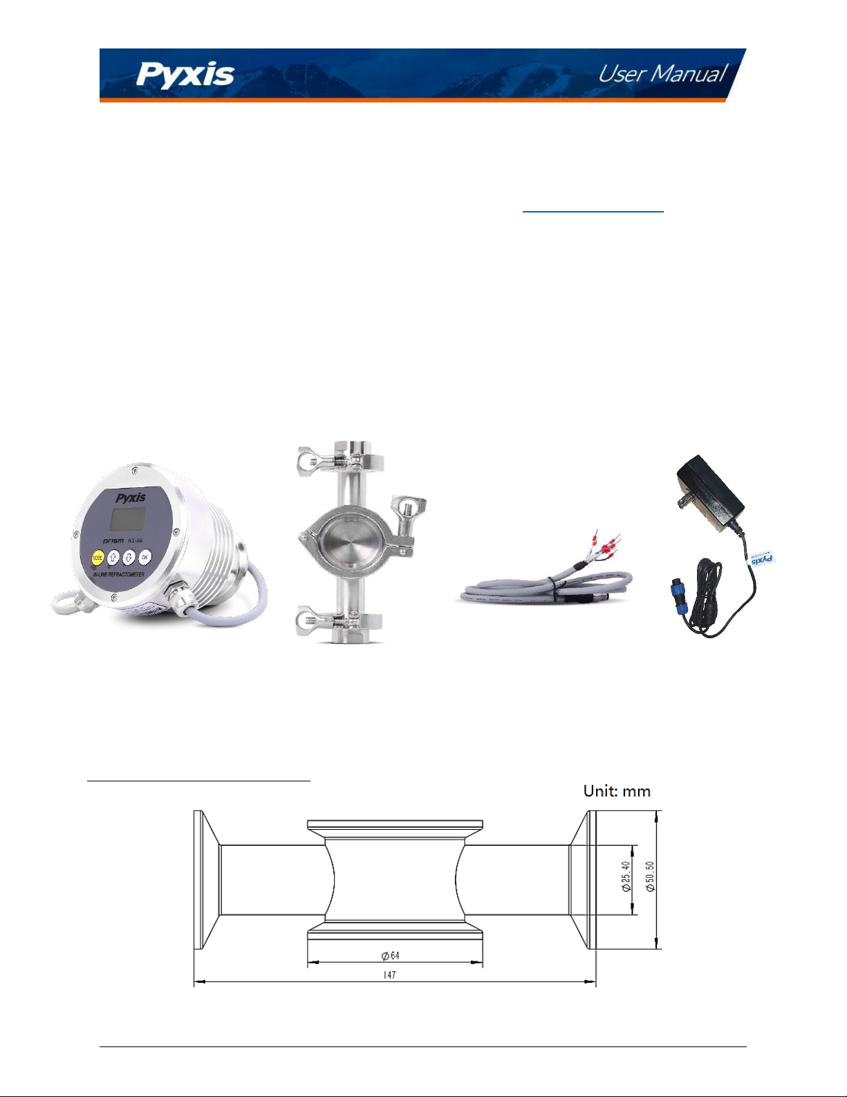
3.1 Standard Accessories .................................................................................................................. 4
3.2 Optional Accessories................................................................................................................... 5
4 Installation ..................................................................................................................................... 5
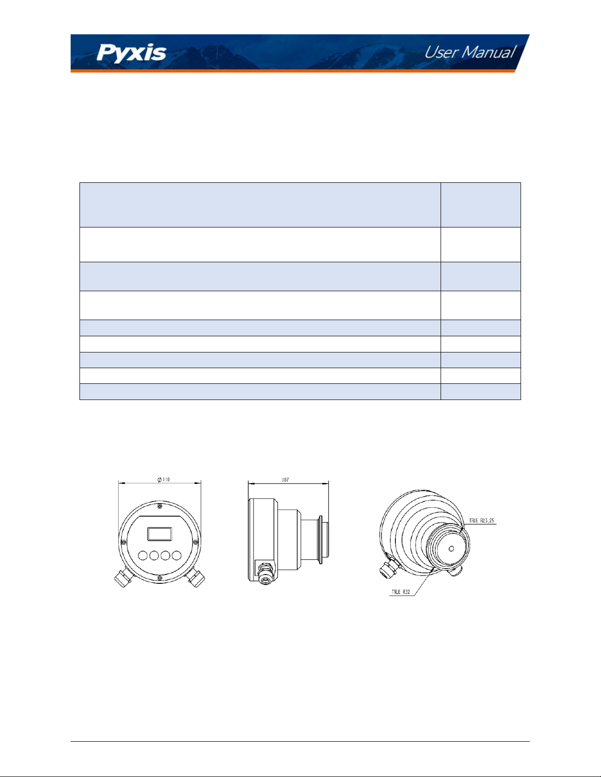
4.1 Main Assembly ........................................................................................................................... 5
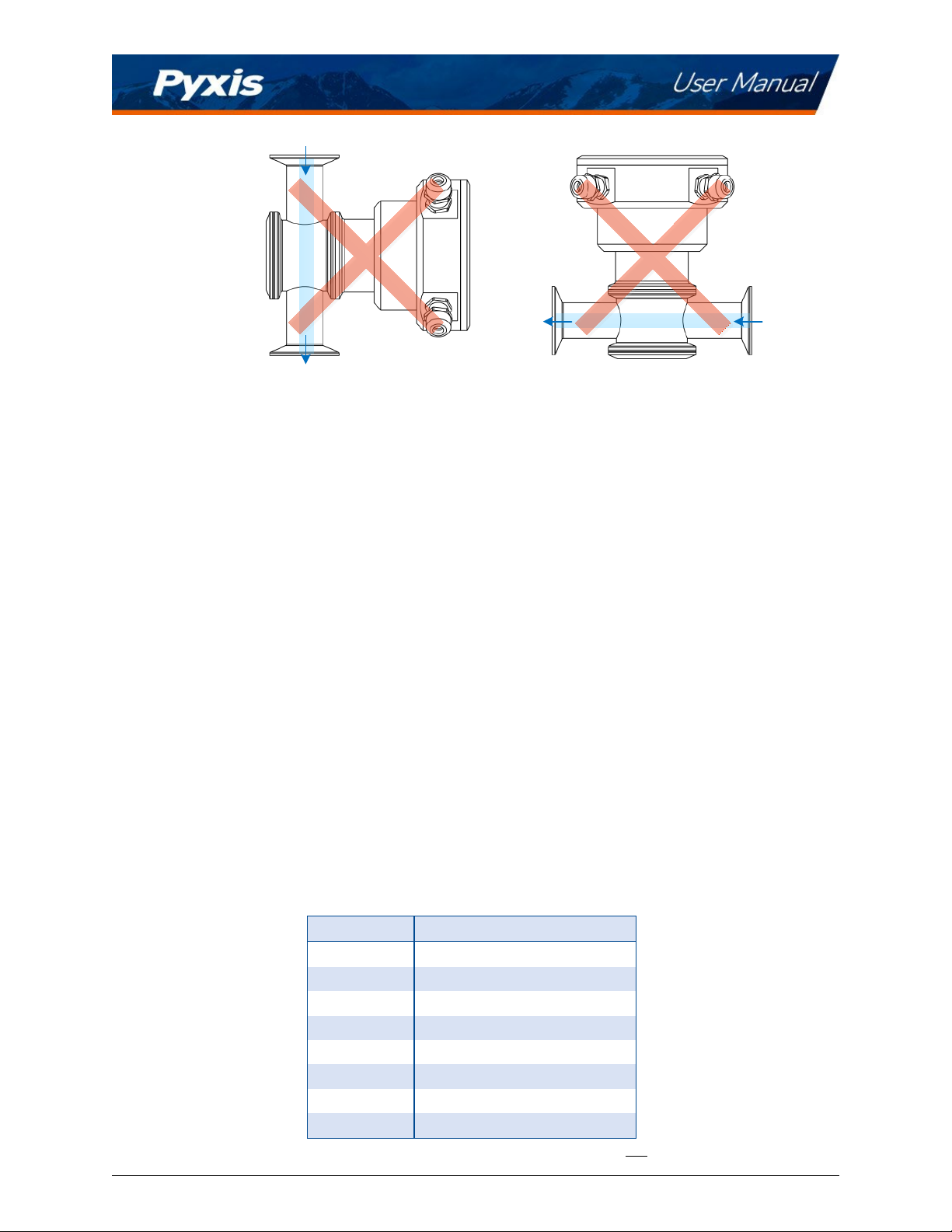
4.2 Piping......................................................................................................................................... 6
4.3 Wiring ........................................................................................................................................ 7
4.4 Connecting via Bluetooth ............................................................................................................ 8
5 Instrument Overview...................................................................................................................... 9
5.1 Key Functions ............................................................................................................................. 9
5.2 Measurement Modes................................................................................................................ 10
5.3 Sensitivity Setup ....................................................................................................................... 10
5.4 Cleaning Cycle Setup................................................................................................................. 10
5.5 Reset Parameters...................................................................................................................... 11
6 Calibration.................................................................................................................................... 12
6.1 Air Calibration of Refractive Index ............................................................................................. 12
6.2 Brix and Other Liquid Concentration Offset Calibration.............................................................. 13
7 Setup and Configuration with uPyxis® Mobile App ....................................................................... 13
7.1 Download uPyxis® Mobile App .................................................................................................. 13
7.2 Connecting to uPyxis® Mobile App ............................................................................................ 14
7.3 Calibration Screen and Reading................................................................................................. 15
7.4 Add/Modify Custom Fluid ......................................................................................................... 15
7.5 Diagnosis Screen....................................................................................................................... 18
7.6 Device Info Screen .................................................................................................................... 19
8 Setup and Calibration with uPyxis® Desktop App.......................................................................... 19
8.1 Install uPyxis® Desktop App....................................................................................................... 19
8.2 Connecting to uPyxis® Desktop App .......................................................................................... 20
8.3 Information Screen ................................................................................................................... 21
8.4 Calibration Screen..................................................................................................................... 22
8.5 Add/Modify Custom Fluid ......................................................................................................... 23
8.6 Diagnosis Screen....................................................................................................................... 24
9 Outputs ........................................................................................................................................ 26
9.1 4–20mA Output Setup .............................................................................................................. 26
9.2 Communication using Modbus RTU........................................................................................... 26
10 Sensor Maintenance and Precaution ........................................................................................ 27
10.1 Methods to Cleaning the Prism RT-50........................................................................................ 27

Prism RT-50 User Manual service@pyxis-lab.com | +1 (866) 203-8397 1
Warranty Information
Confidentiality
The information contained in this manual may be confidential and proprietary and is the property of Pyxis
Lab, Inc. Information disclosed herein shall not be used to manufacture, construct, or otherwise reproduce
the goods described. Information disclosed herein shall not be disclosed to others or made public in any
manner without the express written consent of Pyxis Lab, Inc.
Standard Limited Warranty
Pyxis Lab warrants its products for defects in materials and workmanship. Pyxis Lab will, at its option,
repair or replace instrument components that prove to be defective with new or remanufactured
components (i.e., equivalent to new). The warranty set forth is exclusive and no other warranty, whether
written or oral, is expressed or implied.
Warranty Term
The Pyxis warranty term is thirteen (13) months ex-works. In no event shall the standard limited warranty
coverage extend beyond thirteen (13) months from original shipment date.
Warranty Service
Damaged or dysfunctional instruments may be returned to Pyxis for repair or replacement. In some
instances, replacement instruments may be available for short duration loan or lease.
Pyxis warrants that any labor services provided shall conform to the reasonable standards of technical
competency and performance effective at the time of delivery. All service interventions are to be reviewed
and authorized as correct and complete at the completion of the service by a customer representative or
designate. Pyxis warrants these services for 30 days after the authorization and will correct any qualifying
deficiency in labor provided that the labor service deficiency is exactly related to the originating event. No
other remedy, other than the provision of labor services, may be applicable.
Repair components (parts and materials), but not consumables, provided during a repair, or purchased
individually, are warranted for 90 days ex-works for materials and workmanship. In no event will the
incorporation of a warranted repair component into an instrument extend the whole instrument’s
warranty beyond its original term.
Warranty Shipping
A Repair Materia Authorization (RMA) Number must be obtained from Pyxis Technical Support before any
product can be returned to the factory. Pyxis will pay freight charges to ship replacement or repaired
products to the customer. The customer shall pay freight charges for returning products to Pyxis. Any
product returned to the factory without an RA number will be returned to the customer. To receive an
RMA you can generate a request on our website at https://www.pyxis-lab.com/request-return-or-repair/
Pyxis Technical Support
Contact Pyxis Technical Support at +1 (866) 203-8397 or service@pyxis-lab.com

Prism RT-50 User Manual service@pyxis-lab.com | +1 (866) 203-8397 2
1Introduction
The Pyxis RT-50 Prism is an inline digital refractometer that
measures the refractive index of a liquid sample and provides
a direct reading of highly accurate concentration values for a
wide variety of process applications including cutting fluid
concentration detection. It is a stand-alone device capable of
self-sustained operation, live data display and data logging.
The RT-50 Prism also offers fully integrated 4-20mA and RS-485
Modbus output signals for connectivity to any microprocessor-
based controller, display, PLC or DCS network. The RT-50 Prism
has built-in temperature dependent equations to convert the
optical lens measured sample temperature and refractive
index to the Brix concentration. User defined concentration
curves and output may also be programmed to the RT-50
through the uPyxis APP interface through user entry of know
formula coefficient values. This enables the RT-50 to provide a
user-customized display and output of the concentration of the
material being measured, as desired.
*NOTE* The Prism RT-50 is a very robust sensor and capable of operating in contaminated fluid samples.
It is important, however, to note that users should take all precautions to prevent and filter suspended
solids from the sample stream prior to the sensor to avoid tenacious deposit build-up on the sensor eye. In
highly fouled applications, Pyxis recommends users conduct sensor eye cleaning on a regular basis. Pyxis
Lab offers the Ultra-Sonic RT-50 Cleaning Module Kit (P/N 56208) for installation into the Tri-Clamp Flow
Cell Assembly as an optional accessory allowing for automated online cleaning of the RT-50 refractive
index sensor. Contact www.order@pyxis-lab.com for technical and pricing details of this online cleaning
accessory.
1.1 Main Features
•Dual 4-20 mA output of sample temperature and the unit of display selected via the screen interface
•User customizable product name, concentration and 4-20mA output ranges with uPyxis APP
•RS-485 Modbus RTU output of temperature, refractive index, and other diagnosis parameters
•Built-in temperature dependent equations % BRIX
•User Defined Product Concentration Curve Entry via uPyxis APP
•Local Display and Push-Button Interface
•Optional 110/220VAC – 24 VDC Wall Outlet Powered for Independent Operation w/out controller
•Built-In Historical Data Log up to 56 Days of Storage at 1 Reading Per Minute via uPyxis APP
•Bluetooth Enabled when used with MA-CR Bluetooth Adapter
•Sturdy 316L stainless-steel construction and suitable for harsh application environments
•Convenient Stainless-Steel Tri-Clamp Flow Cell Assembly w ¾-inch NPT Flange
•Easy Installation and Removal for Cleaning and Maintenance – No Tools Needed
•Automatic Cleaning with RT-Series Ultrasonic Cleaning Module Kit (Purchased Separately)

Prism RT-50 User Manual service@pyxis-lab.com | +1 (866) 203-8397 3
2Specifications
Table 1. Prism RT-50 Specifications
ITEM
RT-50 PRISM
P/N
10013
RANGE
OF
MEASUREMENT
Refractive Index: 1.3200 – 1.4000
Brix: 0.00 – 38.00%
Temperature: -20oC – 80oC
RESOLUTION
Refractive Index: 0.0001
Brix and other: 0.1%
ACCURACY
Refractive Index: ±0.0002
Brix and other: ±0.2%
SAMPLE TEMPERATURE
-4 – 158 oF (-10 – 55 oC)
MAX SAMPLE PRESSURE /
FLOW
<142 psi (0.98 MPa) / <13.5 GPM (9.8 ft/s)
ENVIRONMENTAL
TEMPERATURE
14 – 104 oF (-10 – 40 oC)
WEIGHT
3.2 pound (1.45 kg)
DIMENSION
4.33 x 4.2 inch (110 x 107 mm)
PROTECTION
IP-67
LIGHT SOURCE
LED
WET MATERIALS
Sapphire, 316L Stainless steel
SIGNAL OUTPUT
2x 4-20 mA and RS-485 Modbus
POWER
24 VDC (1.5W)
REGULATION
CE / RoHS Marked
* With Pyxis’s continuous improvement policy, these specifications are subject to change without notice.

Prism RT-50 User Manual service@pyxis-lab.com | +1 (866) 203-8397 4
3Unpacking Instrument
Remove the instrument and accessories from the shipping container and inspect each item for any
damage that may have occurred during shipping. Verify that all accessory items are included. If any item
is missing or damaged, please contact Pyxis Lab Customer Service at service@pyxis-lab.com
3.1 Standard Accessories
RT-50 Prism Package (P/N 10013)
•The package should include one RT-50 Prism Refractive Index Sensor w/8Pin Female Cable
•One 316L Stainless Steel Tri-Clamp Flow Cell Assembly (P/N 56206)
•One MA-1.5CR Cable (1.5 Meter/ 4.9 ft 8Pin Male Adapter/Flying Lead) (P/N 50746)
•One Prism RT-Series Wall Outlet Power Supply Kit (110/220VAC/24VDC – 2Pin) (P/N 56207)
Figure 1. RT-50 Prism / Tri-Clamp Flow Cell Assembly / MA-1.5 Flying Lead Cable / 110/220VAC-24VDC Power Supply
Tri-Clamp Flow Assembly Side Diagram

Prism RT-50 User Manual service@pyxis-lab.com | +1 (866) 203-8397 5
3.2 Optional Accessories
The following optional accessories can be ordered from Pyxis Customer Service (order@pyxis-lab.com) or
Pyxis E-Store at https://pyxis-lab.com/shop/.
Table 2. Optional Accessories
Optional / Replacement Accessories
Part
Number
(P/N)
RT-Series Prism Wall Outlet Power Supply Adapter Kit
(Plug In Power Supply Kit - Converts Wall Outlet 110/220VAC to 24VDC for Prism RT-50)56207
MA-CR
(Bluetooth Adapter for 8-Pin Pyxis Sensors for use with uPyxis Mobile & Desktop)
MA-CR
MA-NEB
(USB Bluetooth Adapter for PC to use uPyxis Desktop) MA-NEB
MA-50CR
(50’ Extension Cable w/ 8-Pin Adapters)
50743
Pyxis Probe Cleaning Kit
SER-01
Tri-Clamp Flow Cell Assembly Complete Replacement
56206
Tri-Clamp Flow Cell Assembly Replacement Gasket Kit
56209
RT-Series Ultra-Sonic Cleaning Module Kit
56208
4Installation
4.1 Main Assembly
Unit: mm
Figure 2. Prism RT-50 Sensor Dimensions (mm)
Each Prism RT-50 is provided with a 316L stainless steel Tri-Clamp Inline Flow Assembly with 3/4-inch FNPT
inlet/outlet flanges. A flange and plug are also inserted into a portal opposite of the sensor eye for use
with the RT-Series Ultrasonic Cleaning Module Kit (P/N 56208) in applications requiring automated inline
cleaning.

Prism RT-50 User Manual service@pyxis-lab.com | +1 (866) 203-8397 6
Figure 3. Tri-Clamp Flow Cell Assembly (P/N: 56206)
Table 3. Tri-Clamp Flow Cell Assembly Components
ID #
Description
1
Flow cell with 2.5-inch Port for Prism RT-50 Sensor Head
2
Sensor Tri-Clamp 2.5-inch
3, 4
Tri-Clamp Flow Cell Gasket Kit (P/N: 56209)
5
3/4-inch NPT Flange
6
Flange Tri-Clamp 2-inch
7
Plug Cap
φ
64mm Reserved for Ultra-Sonic Cleaning
4.2 Piping
The Prism RT-50 with Tri-Clamp Flow Cell Assembly should be installed per the diagram provided in Figure
4. Be sure to avoid installations illustrated in Figure 5.
Figure 4. Correct Installations

Prism RT-50 User Manual service@pyxis-lab.com | +1 (866) 203-8397 7
Figure 5. Incorrect Installations
4.3 Wiring
The Prism RT-50 unit offers two (2) cable points of attachment, both terminated with a unique connector
(Figure 6). The Prism RT-50 may be powered via a direct 24VDC supply source (via 8-Pin cable provided
with the Prism RT-50) or by the provided accessory called Prism RT-50 Wall Outlet Power Supply Adapter
Kit (P/N 56207). Explanation of each option below:
Powered by a Direct 24VDC Power Source via 8-Pin Cable Provided with Prism RT-50
For applications where the Prism RT-50 is connected to and directly powered by 24VDC source (Controller,
PLC, DCS etc.), the device should be connected via the 8-Pin Cable and MA-1.5CR Flying Lead Cable. These
cables provide power as well as 4-20mA and RS-485 output communication to the connected device.
Please refer to Table 4 for wire designations of the 8-pin cables.
Powered by a Prism RT-Series Wall Outlet Power Supply Adapter Kit
For applications desiring the Prism RT-50 to be powered by a standard 110/220VAC wall outlet, Pyxis offers
the Prism RT-Series Wall Outlet Power Supply Kit (P/N: 56207). This kit offers a 2-Pin cable and wall outlet
adapter for direct power supply from a standard 110/220VAC wall outlet. *NOTE* In the wall outlet
powering format, there is no need to terminate the power supply portion of the 8-Pin Cable. This cable may
continue to be used in order to pass 4-20mA and RS-485 output signals or for use with the MA-CR Bluetooth
adapter for uPyxis® App access.
Table 4. Wire Designations
Wire Color
Designation
Red
24V +
Brown
24V Power ground
Gray
*
4–20mA -
White
nD/Brix/Others %, 4–20mA +
Pink
Temperature, 4–20ma +
Blue
RS-485 A
Yellow
RS-485 B
Green
RS-485 Ground
* Gray Wire Internally connected to the power ground. 4-20mA is not loop powered.

Prism RT-50 User Manual service@pyxis-lab.com | +1 (866) 203-8397 8
Wall Outlet Power Supply Adapter Kit Optional
Accessory(P/N 56207)
8-Pin 24VDC + 4-20mA + RS-485 Output Cable
(Female Adapter / 10-inches Length)
Included with Each RT-50
MA-1.5CR Flying Lead Cable
(P/N 50746)
Figure 6. Prism RT-50 with RT-Series Wall Outlet Adapter Kit (P/N: 56207) and MA-1.5CR Flying Lead Cable (P/N: 50746)
4.4 Connecting via Bluetooth
Connect the Prism RT-50 to the Pyxis MA-CR Bluetooth adapter (P/N MA-CR) and a 24 VDC power source
according to the figures below. Figure 7 shows that the Prism RT-50 is powered by a controller through
the 8-Pin cable provided with the Prism RT-50. Figure 8 shows the Prism RT-50 is powered by the Prism
RT-50 Wall Outlet Power Supply Adapter (P/N: 56207) through the 2-Pin cable.
*NOTE*uPyxis®Mobile allows mobile devices to wirelessly speak directly to the MA-CR Bluetooth
Adapter. uPyxis® Desktop requires MA-NEB (USB Bluetooth adapter) to be installed in the PC for
wireless access to MA-CR.
MA-NEB-USB Bluetooth Adapter
Figure 7. 24VDC Powered via Controller through 8-Pin Cable and MA-CR Bluetooth Adapter

Prism RT-50 User Manual service@pyxis-lab.com | +1 (866) 203-8397 9
MA-NEB-USB Bluetooth Adapter
Figure 8.
24VDC Powered via 110/220VAC Wall Outlet through Prism RT-Series Wall Outlet Power Supply Adapter (P/N: 56207)
5Instrument Overview
5.1 Key Functions
Figure 9. Prism RT-50 Main Display Screen
Table 5. Prism RT-50 Key Functions
Key
Function Description
MODE
Launch setup function associated with the current mode
↑ and ↓
Select measurement modes (units); select available selections
associated
OK
Selection confirmation, (Press 3S to set the HOME
display)

Prism RT-50 User Manual service@pyxis-lab.com | +1 (866) 203-8397 10
5.2 Measurement Modes
The Prism RT-50 measures the sample refractive index (nD) and temperature. Use the arrow keys to select
the concentration units that are calculated from nD and the temperatures with using the pre-loaded
equations for Brix. The main output of 4-20mA signal value switches with the display concentration
selected per the 4-20mA output scales section 9.1 of this manual.
Figure 10. nD Figure 11. Brix %
5.3 Sensitivity Setup
A higher sensitivity value set will result in a slower sensor response and the displayed value with show less
fluctuation. For applications that require very accurate refractive index measurement, and the refractive
index does not undergo any rapid changes in the time scale of minutes, the sensitivity should be set up to
the highest value of 30.
Figure 12.- Sensitivity
5.4 Cleaning Cycle Setup
RT-50 supports an extended ultrasonic cleaning function using the RT-Series Ultra-Sonic Cleaning Module
Kit (P/N 56208). When working in synchronization with the RT-Series Ultrasonic Cleaning Module, the
working cleaning cycle is set by RT-50 in increments of every 5, 15 or 30 minutes for a cleaning duration
of 5-seconds per cycle. The RT-50 default programmed cleaning time is every 15-minutes. For pricing,
technical data and programming of the Ultra-Sonic Cleaning Module Kit, please contact order@pyxis-
lab.com
Figure 13.– Programming the Clean Cycle Frequency

Prism RT-50 User Manual service@pyxis-lab.com | +1 (866) 203-8397 11
5.5 Reset Parameters
This mode will erase the user’s calibration and setting information, restore the factory calibration and
setting information, including air calibration, brix/liquid concentration offset calibration, sensitivity, etc.
Figure 14.Figure 15.

Prism RT-50 User Manual service@pyxis-lab.com | +1 (866) 203-8397 12
6Calibration
Calibration for refractive index is not required for the RT-50 use. The Prism RT-50 can however be
calibrated in air to correct possible misalignment and aging of the optic components. An offset calibration
for each concentration unit is provided by using a liquid sample with known concentration value.
6.1 Air Calibration of Refractive Index
1. Clean the Prism RT-50 sapphire lens with soft tissue.
2. If any tenacious deposits are present on the sensor lens, you may pre-soak the sensor lens in Pyxis
Probe Cleaning Solution (P/N: SER-01) for 10–15 minutes, then rinse with clean water and wipe with
soft tissue prior to proceeding to air calibration of refractive index.
*NOTE* Please refer to the Section 10.1 Methods to Cleaning the Prism RT-50 for details.
3. After properly cleaning the sensor lens, remove any residual liquid from the sapphire lens.
4. Shield the lens from the ambient light.
5. Press the MODE key on the face of the unit to launch the air calibration interface (Figure 16).
6. Hold the OK key on the face of the unit for 3 seconds to start the air calibration process (Figure 17).
7. Once the calibration is complete, press the MODE key to return to measurement mode (Figure 18).
Figure 16.Figure 17.Figure 18.

Prism RT-50 User Manual service@pyxis-lab.com | +1 (866) 203-8397 13
6.2 Brix and Other Liquid Concentration Offset Calibration
The refractive index value does not require calibration as stated in Section 6.1. The refractive index and
temperature values are internally converted to the desired liquid concentration unit selected through the
display of the sensor interface. This displayed liquid concentration unit value may be calibrated to a known
solution if desired.To do this:
1. Place the Prism RT-50 in the calibration liquid of a known concentration making sure the sensor is
covered from ambient light.
2. Use the arrow keys on the sensor display to select the corresponding concentration unit of your
sample. (i.e., Brix)
3. Press the MODE key on the sensor display to launch the offset calibration interface for the specific
concentration unit selected.
4. Proceed through the screen prompt steps to calibrate unit to the known concentration of liquid
standard.
Figure 19.
7Setup and Configuration with uPyxis® Mobile App
7.1 Download uPyxis® Mobile App
Download uPyxis® Mobile App from Apple App Store or Google Play.
Figure 20.uPyxis® Mobile App installation

Prism RT-50 User Manual service@pyxis-lab.com | +1 (866) 203-8397 14
7.2 Connecting to uPyxis® Mobile App
Connect the Prism RT-50 sensor to a mobile smart phone according to the following steps:
1. Install the MA-CR Bluetooth Adapter on the 8Pin output cable from the RT-
50 as outlined on page 8-9 as seen in Figure 7 (if powered by a controller) or
Figure 8 (if powered by the RT-Series Wall Outlet Power Adapter).
2. Open the uPyxis® Mobile App.
3. In the uPyxis® Mobile App, swipe down with finger on the main screen to refresh the list of available
Pyxis devices. *NOTE* this may take multiple finger swipes for Bluetooth to connect to the device.
4. If the connection is successful, the Prism RT-50 and its Serial Number (S/N) will be displayed (Figure
21).
5. Press on the Prism RT-50 sensor image.
Figure 21.– Discovered RT-50 on uPyxis Mobile APP

Prism RT-50 User Manual service@pyxis-lab.com | +1 (866) 203-8397 15
7.3 Calibration Screen and Reading
When connected, the uPyxis® Mobile App will default to the Calibration screen. From the Calibration
screen, the user can perform the various forms of calibrations as discussed in this manual (see Sections
6.1 and 6.2) by pressing on Air Calibration and Bias Calibration (Offset Calibration). The calibration
objective is determined by the drop-down box selected. Follow the screen instructions for each calibration
step.
The user may also perform a factory reset of all calibration values saved in the device by pressing Restore
Factory and entering ”upyxis” into the prompt.
Setting 4-20mA Range The 4-20mA output range for any concentration scale may be modified by the user,
if the default range is not suitable for you.This feature enables the user to adjust the 4-20mA output
values of the RT-50 for the concentration curve as desired. *NOTE* 20mA value adjustment must be LESS
than the highest default 20mA output value of the concentration selected. (i.e. for BRIX concentration, the
20mA value may be set to 38% or lower). Please refer to Section 9.1 for default 4-20mA output scales of
the RT-50.
Figure 22.– Calibration Screen Interface uPyxis Mobile APP.
7.4 Add/Modify Custom Fluid
In order to adapt to more application scenarios, users can create and add new customized fluids through
the uPyxis APP and display them on the OLED screen. This method will establish a formula between the
new fluid and Brix%, and the accuracy can reach ±0.2%. Modification of the Custom Fluid Name and
Coefficient are also supported via uPyxis.

Prism RT-50 User Manual service@pyxis-lab.com | +1 (866) 203-8397 16
STEP 1 - Name the Custom (New) Fluid
The name should not exceed 7 characters in length. *NOTE* Only alphanumeric and
“
_
”
may be used.
Figure 23.
STEP 2 - Entering at Least 5-sets of Custom Product Concentration Data
The user should then enter at least 5-sets of the Custom (New) Fluid Concentration (%) and to the
corresponding Brix (%) concentration already populated in the table. The uPyxis App will calculate and
establish the coefficient formula between the Custom (New) Fluid Concentration (%) and Brix (%). *NOTE*
If your data correlation coefficient R2is less than 0.8, the uPyxis APP will NOT permit you to proceed to the
next step and users must check their concentration data for accuracy.
Figure 24.

Prism RT-50 User Manual service@pyxis-lab.com | +1 (866) 203-8397 17
STEP 3 - Set Custom (New) Fluid 4-20mA Range & Sensor Output Scale
According to the concentration range of the Custom (New) Fluid, enter the appropriate concentration (%)
of 4mA, and concentration (%) of 20mA to program the 4-20mA output scale from the sensor. *NOTE* It is
important to remember this output scale for programming the signal receiving device accurately (i.e..
Controller, PLC, or Network)
Figure 25.
STEP 4 - Apply the Custom (New) Fluid Settings and Display
Please confirm whether to apply this custom fluid and display it on the OLED screen. Once OK is pressed,
the uPyxis APP will apply this customized firmware to the RT-50 process control board and the unit is now
set to display your custom fluid.
Figure 26.
This manual suits for next models
1
Table of contents
Other Pyxis Measuring Instrument manuals

Pyxis
Pyxis IK-765SS-O3 User manual

Pyxis
Pyxis PRISM RT-100 User manual

Pyxis
Pyxis ST-500 User manual

Pyxis
Pyxis SP-400 User manual

Pyxis
Pyxis DW-739 Series User manual

Pyxis
Pyxis SP-380P User manual

Pyxis
Pyxis SP-900 User manual

Pyxis
Pyxis ST-600 Quick start guide

Pyxis
Pyxis SP-210 User manual

Pyxis
Pyxis SP-800 Reference guide