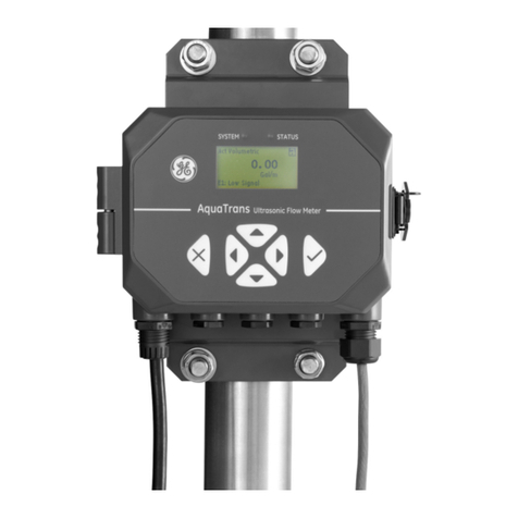
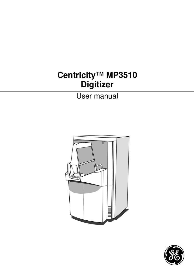
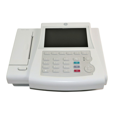
GE AquaTrans AT600 User manual

GE
Measurement & Control Flow
910-312 Rev. A
December 2014
AT600
User’s Manual


www.ge-mcs.com
©2014 General Electric Company. All rights reserved.
Technical content subject to change without notice.
AT600
Panametrics Ultrasonic Flowmeter for Liquids
User’s Manual
910-312 Rev. A
December 2014

ii
[no content intended for this page]

AT600 User’s Manual iii
Contents
Chapter 1. Introduction
1.1 Overview. . . . . . . . . . . . . . . . . . . . . . . . . . . . . . . . . . . . . . . . . . . . . . . . . . . . . . . . . . . . . . . . . . . . . . . . . . . . . . . . . . . . . . . . . . . . . . .1
1.2 Theory of Operation . . . . . . . . . . . . . . . . . . . . . . . . . . . . . . . . . . . . . . . . . . . . . . . . . . . . . . . . . . . . . . . . . . . . . . . . . . . . . . . . . . . .2
1.2.1 Transit-Time Flow Measurement . . . . . . . . . . . . . . . . . . . . . . . . . . . . . . . . . . . . . . . . . . . . . . . . . . . . . . . . . . . . . . . . . . .2
Chapter 2. Installation
2.1 Introduction. . . . . . . . . . . . . . . . . . . . . . . . . . . . . . . . . . . . . . . . . . . . . . . . . . . . . . . . . . . . . . . . . . . . . . . . . . . . . . . . . . . . . . . . . . . .3
2.2 Unpacking the AT600 system . . . . . . . . . . . . . . . . . . . . . . . . . . . . . . . . . . . . . . . . . . . . . . . . . . . . . . . . . . . . . . . . . . . . . . . . . . .4
2.3 Installing the Electronics Enclosure . . . . . . . . . . . . . . . . . . . . . . . . . . . . . . . . . . . . . . . . . . . . . . . . . . . . . . . . . . . . . . . . . . . . . .5
2.4 Installing the Clamp-on Fixture And Transducer System . . . . . . . . . . . . . . . . . . . . . . . . . . . . . . . . . . . . . . . . . . . . . . . . . .7
2.4.1 Clamp-on Fixture and Transducer Location. . . . . . . . . . . . . . . . . . . . . . . . . . . . . . . . . . . . . . . . . . . . . . . . . . . . . . . . .7
2.4.2 Mounting Clamp-on Fixture Onto Pipe (AT6 Transducers) . . . . . . . . . . . . . . . . . . . . . . . . . . . . . . . . . . . . . . . . . . . .8
2.4.2a Dual Traverse Installation at Transducer Spacing Range 0 to 250mm . . . . . . . . . . . . . . . . . . . . . . . . .8
2.4.2b Dual Traverse Installation at Transducer Spacing Range 250 to 750mm . . . . . . . . . . . . . . . . . . . . . .10
2.4.2c Single Traverse Installation at Transducer Spacing Range 0 to 250mm . . . . . . . . . . . . . . . . . . . . . . .13
2.4.2d Single Traverse Installation at Transducer Spacing Range 250 to 750mm . . . . . . . . . . . . . . . . . . . .14
2.5 Installing C-RS Fixture and Transducer System. . . . . . . . . . . . . . . . . . . . . . . . . . . . . . . . . . . . . . . . . . . . . . . . . . . . . . . . . .15
2.5.1 Installation Guide for C-RS transducer. . . . . . . . . . . . . . . . . . . . . . . . . . . . . . . . . . . . . . . . . . . . . . . . . . . . . . . . . . . . .15
2.5.2 Install Cable Adaptor for C-RS transducer and AT6 cable . . . . . . . . . . . . . . . . . . . . . . . . . . . . . . . . . . . . . . . . . . .15
2.6 Making Electrical Connections . . . . . . . . . . . . . . . . . . . . . . . . . . . . . . . . . . . . . . . . . . . . . . . . . . . . . . . . . . . . . . . . . . . . . . . . .16
2.6.1 Wiring the Line Power . . . . . . . . . . . . . . . . . . . . . . . . . . . . . . . . . . . . . . . . . . . . . . . . . . . . . . . . . . . . . . . . . . . . . . . . . . . .17
2.6.2 Wiring the Transducers . . . . . . . . . . . . . . . . . . . . . . . . . . . . . . . . . . . . . . . . . . . . . . . . . . . . . . . . . . . . . . . . . . . . . . . . . . .19
2.6.3 Wiring System Ground. . . . . . . . . . . . . . . . . . . . . . . . . . . . . . . . . . . . . . . . . . . . . . . . . . . . . . . . . . . . . . . . . . . . . . . . . . . .19
2.6.4 Wiring Analog Output/HART Communication . . . . . . . . . . . . . . . . . . . . . . . . . . . . . . . . . . . . . . . . . . . . . . . . . . . . . .20
2.6.5 Wiring Modbus Communication. . . . . . . . . . . . . . . . . . . . . . . . . . . . . . . . . . . . . . . . . . . . . . . . . . . . . . . . . . . . . . . . . . .21
2.6.6 Wiring Frequency/Totalizer/Alarm Output . . . . . . . . . . . . . . . . . . . . . . . . . . . . . . . . . . . . . . . . . . . . . . . . . . . . . . . . .21
2.6.7 Wiring Gate Input . . . . . . . . . . . . . . . . . . . . . . . . . . . . . . . . . . . . . . . . . . . . . . . . . . . . . . . . . . . . . . . . . . . . . . . . . . . . . . . .22

Contents
iv AT600 User’s Manual
Chapter 3. Initial Setup and Programming
3.1 Introduction. . . . . . . . . . . . . . . . . . . . . . . . . . . . . . . . . . . . . . . . . . . . . . . . . . . . . . . . . . . . . . . . . . . . . . . . . . . . . . . . . . . . . . . . . . .23
3.2 AT600 Keypad Operation . . . . . . . . . . . . . . . . . . . . . . . . . . . . . . . . . . . . . . . . . . . . . . . . . . . . . . . . . . . . . . . . . . . . . . . . . . . . . .24
3.3 Display Programming . . . . . . . . . . . . . . . . . . . . . . . . . . . . . . . . . . . . . . . . . . . . . . . . . . . . . . . . . . . . . . . . . . . . . . . . . . . . . . . . .25
3.3.1 Changing Value for One or Two-Variable Screens . . . . . . . . . . . . . . . . . . . . . . . . . . . . . . . . . . . . . . . . . . . . . . . . . .25
3.3.2 Changing Measurement Type for One- or Two-Variable Screens . . . . . . . . . . . . . . . . . . . . . . . . . . . . . . . . . . . .26
3.3.3 Changing the Measurement Type or Value for Totalizer Screens . . . . . . . . . . . . . . . . . . . . . . . . . . . . . . . . . . . .27
3.3.4 Starting or Stopping Totalizer Measurement . . . . . . . . . . . . . . . . . . . . . . . . . . . . . . . . . . . . . . . . . . . . . . . . . . . . . . .29
3.3.5 Resetting the Totalizer. . . . . . . . . . . . . . . . . . . . . . . . . . . . . . . . . . . . . . . . . . . . . . . . . . . . . . . . . . . . . . . . . . . . . . . . . . . .30
3.4 Entering the Main Menu (Lock Button) . . . . . . . . . . . . . . . . . . . . . . . . . . . . . . . . . . . . . . . . . . . . . . . . . . . . . . . . . . . . . . . . . .31
3.4.1 Display Format. . . . . . . . . . . . . . . . . . . . . . . . . . . . . . . . . . . . . . . . . . . . . . . . . . . . . . . . . . . . . . . . . . . . . . . . . . . . . . . . . . .31
3.4.2 Keypad Lockout. . . . . . . . . . . . . . . . . . . . . . . . . . . . . . . . . . . . . . . . . . . . . . . . . . . . . . . . . . . . . . . . . . . . . . . . . . . . . . . . . .32
3.4.3 Language. . . . . . . . . . . . . . . . . . . . . . . . . . . . . . . . . . . . . . . . . . . . . . . . . . . . . . . . . . . . . . . . . . . . . . . . . . . . . . . . . . . . . . . .33
3.4.4 Program/Program Review . . . . . . . . . . . . . . . . . . . . . . . . . . . . . . . . . . . . . . . . . . . . . . . . . . . . . . . . . . . . . . . . . . . . . . . .33
3.4.5 Program Review . . . . . . . . . . . . . . . . . . . . . . . . . . . . . . . . . . . . . . . . . . . . . . . . . . . . . . . . . . . . . . . . . . . . . . . . . . . . . . . . .34
3.4.6 Program . . . . . . . . . . . . . . . . . . . . . . . . . . . . . . . . . . . . . . . . . . . . . . . . . . . . . . . . . . . . . . . . . . . . . . . . . . . . . . . . . . . . . . . . .34
3.5 User Preferences . . . . . . . . . . . . . . . . . . . . . . . . . . . . . . . . . . . . . . . . . . . . . . . . . . . . . . . . . . . . . . . . . . . . . . . . . . . . . . . . . . . . . .35
3.5.1 Setting. . . . . . . . . . . . . . . . . . . . . . . . . . . . . . . . . . . . . . . . . . . . . . . . . . . . . . . . . . . . . . . . . . . . . . . . . . . . . . . . . . . . . . . . . . .35
3.5.2 Units Setting . . . . . . . . . . . . . . . . . . . . . . . . . . . . . . . . . . . . . . . . . . . . . . . . . . . . . . . . . . . . . . . . . . . . . . . . . . . . . . . . . . . . .36
3.5.3 Density . . . . . . . . . . . . . . . . . . . . . . . . . . . . . . . . . . . . . . . . . . . . . . . . . . . . . . . . . . . . . . . . . . . . . . . . . . . . . . . . . . . . . . . . . .37
3.5.4 Password . . . . . . . . . . . . . . . . . . . . . . . . . . . . . . . . . . . . . . . . . . . . . . . . . . . . . . . . . . . . . . . . . . . . . . . . . . . . . . . . . . . . . . . .37
3.5.5 Display . . . . . . . . . . . . . . . . . . . . . . . . . . . . . . . . . . . . . . . . . . . . . . . . . . . . . . . . . . . . . . . . . . . . . . . . . . . . . . . . . . . . . . . . . .38
3.5.5a Backlight. . . . . . . . . . . . . . . . . . . . . . . . . . . . . . . . . . . . . . . . . . . . . . . . . . . . . . . . . . . . . . . . . . . . . . . . . . . . . . . . . .38
3.5.5b Timeout . . . . . . . . . . . . . . . . . . . . . . . . . . . . . . . . . . . . . . . . . . . . . . . . . . . . . . . . . . . . . . . . . . . . . . . . . . . . . . . . . . .38
3.6 Inputs/Outputs. . . . . . . . . . . . . . . . . . . . . . . . . . . . . . . . . . . . . . . . . . . . . . . . . . . . . . . . . . . . . . . . . . . . . . . . . . . . . . . . . . . . . . . .40
3.6.1 Programming the Analog Output Menu . . . . . . . . . . . . . . . . . . . . . . . . . . . . . . . . . . . . . . . . . . . . . . . . . . . . . . . . . . .40
3.6.1a Setting Analog Measurements . . . . . . . . . . . . . . . . . . . . . . . . . . . . . . . . . . . . . . . . . . . . . . . . . . . . . . . . . . . . .41
3.6.1b Setting Base Value and Full Value . . . . . . . . . . . . . . . . . . . . . . . . . . . . . . . . . . . . . . . . . . . . . . . . . . . . . . . . . .41
3.6.1c Calibrate the Output . . . . . . . . . . . . . . . . . . . . . . . . . . . . . . . . . . . . . . . . . . . . . . . . . . . . . . . . . . . . . . . . . . . . . . .42
3.6.1d Setting Error Handling . . . . . . . . . . . . . . . . . . . . . . . . . . . . . . . . . . . . . . . . . . . . . . . . . . . . . . . . . . . . . . . . . . . . .42
3.6.2 Programming the Digital Output Menu . . . . . . . . . . . . . . . . . . . . . . . . . . . . . . . . . . . . . . . . . . . . . . . . . . . . . . . . . . . .43
3.6.2a Disable the Digital Output. . . . . . . . . . . . . . . . . . . . . . . . . . . . . . . . . . . . . . . . . . . . . . . . . . . . . . . . . . . . . . . . . .44
3.6.2b Setting the Pulse Output . . . . . . . . . . . . . . . . . . . . . . . . . . . . . . . . . . . . . . . . . . . . . . . . . . . . . . . . . . . . . . . . . . .44
3.6.2c Setting the Frequency . . . . . . . . . . . . . . . . . . . . . . . . . . . . . . . . . . . . . . . . . . . . . . . . . . . . . . . . . . . . . . . . . . . . .47
3.6.2d Setting the Alarm . . . . . . . . . . . . . . . . . . . . . . . . . . . . . . . . . . . . . . . . . . . . . . . . . . . . . . . . . . . . . . . . . . . . . . . . . .49
3.6.3 Programming Modbus/Service Port . . . . . . . . . . . . . . . . . . . . . . . . . . . . . . . . . . . . . . . . . . . . . . . . . . . . . . . . . . . . . . .52
3.6.4 Programming Digital Communications . . . . . . . . . . . . . . . . . . . . . . . . . . . . . . . . . . . . . . . . . . . . . . . . . . . . . . . . . . . .52
3.6.4a MODBUS . . . . . . . . . . . . . . . . . . . . . . . . . . . . . . . . . . . . . . . . . . . . . . . . . . . . . . . . . . . . . . . . . . . . . . . . . . . . . . . . . .52
3.6.4b HART. . . . . . . . . . . . . . . . . . . . . . . . . . . . . . . . . . . . . . . . . . . . . . . . . . . . . . . . . . . . . . . . . . . . . . . . . . . . . . . . . . . . . .54
3.7 Sensor Setup. . . . . . . . . . . . . . . . . . . . . . . . . . . . . . . . . . . . . . . . . . . . . . . . . . . . . . . . . . . . . . . . . . . . . . . . . . . . . . . . . . . . . . . . . .56
3.7.1 Programming the Meter Setup. . . . . . . . . . . . . . . . . . . . . . . . . . . . . . . . . . . . . . . . . . . . . . . . . . . . . . . . . . . . . . . . . . . .57

AT600 User’s Manual v
Contents
3.7.1a Setting Zero Cutoff. . . . . . . . . . . . . . . . . . . . . . . . . . . . . . . . . . . . . . . . . . . . . . . . . . . . . . . . . . . . . . . . . . . . . . . . .57
3.7.2 Programming the Pipe. . . . . . . . . . . . . . . . . . . . . . . . . . . . . . . . . . . . . . . . . . . . . . . . . . . . . . . . . . . . . . . . . . . . . . . . . . . .58
3.7.2a Setting Pipe OD/ID/Wall Thickness. . . . . . . . . . . . . . . . . . . . . . . . . . . . . . . . . . . . . . . . . . . . . . . . . . . . . . . . . .58
3.7.2b Setting Pipe Material . . . . . . . . . . . . . . . . . . . . . . . . . . . . . . . . . . . . . . . . . . . . . . . . . . . . . . . . . . . . . . . . . . . . . . .59
3.7.2c Setting the Lining . . . . . . . . . . . . . . . . . . . . . . . . . . . . . . . . . . . . . . . . . . . . . . . . . . . . . . . . . . . . . . . . . . . . . . . . . .60
3.7.3 Programming the Transducer. . . . . . . . . . . . . . . . . . . . . . . . . . . . . . . . . . . . . . . . . . . . . . . . . . . . . . . . . . . . . . . . . . . . .62
3.7.3a Setting the Standard Transducer . . . . . . . . . . . . . . . . . . . . . . . . . . . . . . . . . . . . . . . . . . . . . . . . . . . . . . . . . . .62
3.7.3b Setting a Special Transducer . . . . . . . . . . . . . . . . . . . . . . . . . . . . . . . . . . . . . . . . . . . . . . . . . . . . . . . . . . . . . . .65
3.7.4 Programming the Traverses . . . . . . . . . . . . . . . . . . . . . . . . . . . . . . . . . . . . . . . . . . . . . . . . . . . . . . . . . . . . . . . . . . . . . .68
3.7.5 Programming the Fluid Type . . . . . . . . . . . . . . . . . . . . . . . . . . . . . . . . . . . . . . . . . . . . . . . . . . . . . . . . . . . . . . . . . . . . . .69
3.7.6 Programming the Fluid Temperature . . . . . . . . . . . . . . . . . . . . . . . . . . . . . . . . . . . . . . . . . . . . . . . . . . . . . . . . . . . . . .70
3.7.7 Programming the Transducer Spacing . . . . . . . . . . . . . . . . . . . . . . . . . . . . . . . . . . . . . . . . . . . . . . . . . . . . . . . . . . . .71
Chapter 4. Error Codes and Troubleshooting
4.1 Error Display in the User Interface . . . . . . . . . . . . . . . . . . . . . . . . . . . . . . . . . . . . . . . . . . . . . . . . . . . . . . . . . . . . . . . . . . . . . .73
4.1.1 Error Header . . . . . . . . . . . . . . . . . . . . . . . . . . . . . . . . . . . . . . . . . . . . . . . . . . . . . . . . . . . . . . . . . . . . . . . . . . . . . . . . . . . . .73
4.1.2 Flow Error String . . . . . . . . . . . . . . . . . . . . . . . . . . . . . . . . . . . . . . . . . . . . . . . . . . . . . . . . . . . . . . . . . . . . . . . . . . . . . . . . .73
4.1.2a E1: Low Signal . . . . . . . . . . . . . . . . . . . . . . . . . . . . . . . . . . . . . . . . . . . . . . . . . . . . . . . . . . . . . . . . . . . . . . . . . . . . .73
4.1.2b E2: Sound Speed Error . . . . . . . . . . . . . . . . . . . . . . . . . . . . . . . . . . . . . . . . . . . . . . . . . . . . . . . . . . . . . . . . . . . . .73
4.1.2c E3: Velocity Range . . . . . . . . . . . . . . . . . . . . . . . . . . . . . . . . . . . . . . . . . . . . . . . . . . . . . . . . . . . . . . . . . . . . . . . . .73
4.1.2d E4: Signal Quality . . . . . . . . . . . . . . . . . . . . . . . . . . . . . . . . . . . . . . . . . . . . . . . . . . . . . . . . . . . . . . . . . . . . . . . . . .74
4.1.2e E5: Amplitude Error . . . . . . . . . . . . . . . . . . . . . . . . . . . . . . . . . . . . . . . . . . . . . . . . . . . . . . . . . . . . . . . . . . . . . . . .74
4.1.2f E6: Cycle Skip . . . . . . . . . . . . . . . . . . . . . . . . . . . . . . . . . . . . . . . . . . . . . . . . . . . . . . . . . . . . . . . . . . . . . . . . . . . . . .74
4.2 Diagnostics . . . . . . . . . . . . . . . . . . . . . . . . . . . . . . . . . . . . . . . . . . . . . . . . . . . . . . . . . . . . . . . . . . . . . . . . . . . . . . . . . . . . . . . . . . .74
4.2.1 Introduction. . . . . . . . . . . . . . . . . . . . . . . . . . . . . . . . . . . . . . . . . . . . . . . . . . . . . . . . . . . . . . . . . . . . . . . . . . . . . . . . . . . . . .74
4.2.2 Flowcell Problems . . . . . . . . . . . . . . . . . . . . . . . . . . . . . . . . . . . . . . . . . . . . . . . . . . . . . . . . . . . . . . . . . . . . . . . . . . . . . . . .75
4.2.2a Fluid Problems. . . . . . . . . . . . . . . . . . . . . . . . . . . . . . . . . . . . . . . . . . . . . . . . . . . . . . . . . . . . . . . . . . . . . . . . . . . . .75
4.2.2b Pipe Problems . . . . . . . . . . . . . . . . . . . . . . . . . . . . . . . . . . . . . . . . . . . . . . . . . . . . . . . . . . . . . . . . . . . . . . . . . . . . .76
4.2.3 Transducer Problems . . . . . . . . . . . . . . . . . . . . . . . . . . . . . . . . . . . . . . . . . . . . . . . . . . . . . . . . . . . . . . . . . . . . . . . . . . . . .76
Chapter 5. Communication
5.1 MODBUS . . . . . . . . . . . . . . . . . . . . . . . . . . . . . . . . . . . . . . . . . . . . . . . . . . . . . . . . . . . . . . . . . . . . . . . . . . . . . . . . . . . . . . . . . . . . . .77
5.1.1 Introduction. . . . . . . . . . . . . . . . . . . . . . . . . . . . . . . . . . . . . . . . . . . . . . . . . . . . . . . . . . . . . . . . . . . . . . . . . . . . . . . . . . . . . .77
5.1.2 MODBUS Map . . . . . . . . . . . . . . . . . . . . . . . . . . . . . . . . . . . . . . . . . . . . . . . . . . . . . . . . . . . . . . . . . . . . . . . . . . . . . . . . . . . .77
5.2 HART. . . . . . . . . . . . . . . . . . . . . . . . . . . . . . . . . . . . . . . . . . . . . . . . . . . . . . . . . . . . . . . . . . . . . . . . . . . . . . . . . . . . . . . . . . . . . . . . . .86
5.2.1 Device Identification. . . . . . . . . . . . . . . . . . . . . . . . . . . . . . . . . . . . . . . . . . . . . . . . . . . . . . . . . . . . . . . . . . . . . . . . . . . . . .86
5.2.2 Commands . . . . . . . . . . . . . . . . . . . . . . . . . . . . . . . . . . . . . . . . . . . . . . . . . . . . . . . . . . . . . . . . . . . . . . . . . . . . . . . . . . . . . .86
5.2.2a Universal Commands . . . . . . . . . . . . . . . . . . . . . . . . . . . . . . . . . . . . . . . . . . . . . . . . . . . . . . . . . . . . . . . . . . . . . .86
5.2.2b Common Commands . . . . . . . . . . . . . . . . . . . . . . . . . . . . . . . . . . . . . . . . . . . . . . . . . . . . . . . . . . . . . . . . . . . . . .87

Contents
vi AT600 User’s Manual
5.2.2c Device Specific Commands . . . . . . . . . . . . . . . . . . . . . . . . . . . . . . . . . . . . . . . . . . . . . . . . . . . . . . . . . . . . . . . .88
5.1 Additional Device Status . . . . . . . . . . . . . . . . . . . . . . . . . . . . . . . . . . . . . . . . . . . . . . . . . . . . . . . . . . . . . . . . . . . . . . . . . . . . . 147
5.2 Device Variables . . . . . . . . . . . . . . . . . . . . . . . . . . . . . . . . . . . . . . . . . . . . . . . . . . . . . . . . . . . . . . . . . . . . . . . . . . . . . . . . . . . . 148
5.3 HART Engineering Units. . . . . . . . . . . . . . . . . . . . . . . . . . . . . . . . . . . . . . . . . . . . . . . . . . . . . . . . . . . . . . . . . . . . . . . . . . . . . . 149
Appendix A. Specifications
A.1 Operation and Performance . . . . . . . . . . . . . . . . . . . . . . . . . . . . . . . . . . . . . . . . . . . . . . . . . . . . . . . . . . . . . . . . . . . . . . . . . 153
A.1.1 Fluid Types . . . . . . . . . . . . . . . . . . . . . . . . . . . . . . . . . . . . . . . . . . . . . . . . . . . . . . . . . . . . . . . . . . . . . . . . . . . . . . . . . . . . 153
A.1.2 Flow Measurement . . . . . . . . . . . . . . . . . . . . . . . . . . . . . . . . . . . . . . . . . . . . . . . . . . . . . . . . . . . . . . . . . . . . . . . . . . . . 153
A.1.2a Meter Sizes. . . . . . . . . . . . . . . . . . . . . . . . . . . . . . . . . . . . . . . . . . . . . . . . . . . . . . . . . . . . . . . . . . . . . . . . . . . . . . 153
A.1.2b Accuracy. . . . . . . . . . . . . . . . . . . . . . . . . . . . . . . . . . . . . . . . . . . . . . . . . . . . . . . . . . . . . . . . . . . . . . . . . . . . . . . . 153
A.1.2c Calibration Fluid . . . . . . . . . . . . . . . . . . . . . . . . . . . . . . . . . . . . . . . . . . . . . . . . . . . . . . . . . . . . . . . . . . . . . . . . . 153
A.1.2d Repeatability . . . . . . . . . . . . . . . . . . . . . . . . . . . . . . . . . . . . . . . . . . . . . . . . . . . . . . . . . . . . . . . . . . . . . . . . . . . . 153
A.1.2e Range (Bidirectional) . . . . . . . . . . . . . . . . . . . . . . . . . . . . . . . . . . . . . . . . . . . . . . . . . . . . . . . . . . . . . . . . . . . . . 153
A.1.2f Rangeability (Overall). . . . . . . . . . . . . . . . . . . . . . . . . . . . . . . . . . . . . . . . . . . . . . . . . . . . . . . . . . . . . . . . . . . . . 153
A.2 Meter Body/Transducer . . . . . . . . . . . . . . . . . . . . . . . . . . . . . . . . . . . . . . . . . . . . . . . . . . . . . . . . . . . . . . . . . . . . . . . . . . . . . 154
A.2.1 Meter Body Material . . . . . . . . . . . . . . . . . . . . . . . . . . . . . . . . . . . . . . . . . . . . . . . . . . . . . . . . . . . . . . . . . . . . . . . . . . . 154
A.2.2 AT6 Transducer System and Material . . . . . . . . . . . . . . . . . . . . . . . . . . . . . . . . . . . . . . . . . . . . . . . . . . . . . . . . . . . 154
A.2.3 C-RS Transducer System and Material . . . . . . . . . . . . . . . . . . . . . . . . . . . . . . . . . . . . . . . . . . . . . . . . . . . . . . . . . . 154
A.2.4 Meter Temperature Ranges . . . . . . . . . . . . . . . . . . . . . . . . . . . . . . . . . . . . . . . . . . . . . . . . . . . . . . . . . . . . . . . . . . . . 154
A.2.5 AT6 Transducer Temperature Ranges . . . . . . . . . . . . . . . . . . . . . . . . . . . . . . . . . . . . . . . . . . . . . . . . . . . . . . . . . . . 154
A.2.6 C-RS Transducer Temperature Ranges . . . . . . . . . . . . . . . . . . . . . . . . . . . . . . . . . . . . . . . . . . . . . . . . . . . . . . . . . . 154
A.2.7 Humidity Range. . . . . . . . . . . . . . . . . . . . . . . . . . . . . . . . . . . . . . . . . . . . . . . . . . . . . . . . . . . . . . . . . . . . . . . . . . . . . . . . 154
A.2.8 Altitude Range . . . . . . . . . . . . . . . . . . . . . . . . . . . . . . . . . . . . . . . . . . . . . . . . . . . . . . . . . . . . . . . . . . . . . . . . . . . . . . . . . 154
A.2.9 CAT Transducer Cables . . . . . . . . . . . . . . . . . . . . . . . . . . . . . . . . . . . . . . . . . . . . . . . . . . . . . . . . . . . . . . . . . . . . . . . . . 154
A.2.10 Wiring Cable Specifications and Requirements . . . . . . . . . . . . . . . . . . . . . . . . . . . . . . . . . . . . . . . . . . . . . . . . . 155
A.2.11 Cable Fixing Requirement and Gland Torque . . . . . . . . . . . . . . . . . . . . . . . . . . . . . . . . . . . . . . . . . . . . . . . . . . . 155
A.3 Electronics . . . . . . . . . . . . . . . . . . . . . . . . . . . . . . . . . . . . . . . . . . . . . . . . . . . . . . . . . . . . . . . . . . . . . . . . . . . . . . . . . . . . . . . . . . 156
A.3.1 Enclosures. . . . . . . . . . . . . . . . . . . . . . . . . . . . . . . . . . . . . . . . . . . . . . . . . . . . . . . . . . . . . . . . . . . . . . . . . . . . . . . . . . . . . 156
A.3.2 Weatherproof . . . . . . . . . . . . . . . . . . . . . . . . . . . . . . . . . . . . . . . . . . . . . . . . . . . . . . . . . . . . . . . . . . . . . . . . . . . . . . . . . 156
A.3.3 Electronics Classifications (Pending) . . . . . . . . . . . . . . . . . . . . . . . . . . . . . . . . . . . . . . . . . . . . . . . . . . . . . . . . . . . . 156
A.3.4 Display Languages. . . . . . . . . . . . . . . . . . . . . . . . . . . . . . . . . . . . . . . . . . . . . . . . . . . . . . . . . . . . . . . . . . . . . . . . . . . . . 156
A.3.5 Keypad . . . . . . . . . . . . . . . . . . . . . . . . . . . . . . . . . . . . . . . . . . . . . . . . . . . . . . . . . . . . . . . . . . . . . . . . . . . . . . . . . . . . . . . . 156
A.3.6 Inputs/Outputs . . . . . . . . . . . . . . . . . . . . . . . . . . . . . . . . . . . . . . . . . . . . . . . . . . . . . . . . . . . . . . . . . . . . . . . . . . . . . . . . 156
Appendix B. Data Records
B.1 Service Record . . . . . . . . . . . . . . . . . . . . . . . . . . . . . . . . . . . . . . . . . . . . . . . . . . . . . . . . . . . . . . . . . . . . . . . . . . . . . . . . . . . . . . 157
B.1.1 Data Entry . . . . . . . . . . . . . . . . . . . . . . . . . . . . . . . . . . . . . . . . . . . . . . . . . . . . . . . . . . . . . . . . . . . . . . . . . . . . . . . . . . . . . 157
B.2 Initial Settings . . . . . . . . . . . . . . . . . . . . . . . . . . . . . . . . . . . . . . . . . . . . . . . . . . . . . . . . . . . . . . . . . . . . . . . . . . . . . . . . . . . . . . . 159
B.3 Diagnostic Parameters . . . . . . . . . . . . . . . . . . . . . . . . . . . . . . . . . . . . . . . . . . . . . . . . . . . . . . . . . . . . . . . . . . . . . . . . . . . . . . 160
Appendix C. Menu Maps

AT600 User’s Manual vii
Preface
Information Paragraphs
Note: These paragraphs provide information that provides a deeper understanding of the situation, but is not
essential to the proper completion of the instructions.
IMPORTANT: These paragraphs provide information that emphasizes instructions that are essential to proper setup of
the equipment. Failure to follow these instructions carefully may cause unreliable performance.
Safety Issues
Auxiliary Equipment
Local Safety Standards
The user must make sure that he operates all auxiliary equipment in accordance with local codes, standards,
regulations, or laws applicable to safety.
Working Area
CAUTION! This symbol indicates a risk of potential minor personal injury and/or severe damage to
the equipment, unless these instructions are followed carefully.
WARNING! This symbol indicates a risk of potential serious personal injury, unless these
instructions are followed carefully.
WARNING! It is the responsibility of the user to make sure all local, county, state and national
codes, regulations, rules and laws related to safety and safe operating conditions are met for each
installation. The safety of any system incorporating the equipment is the responsibility of the
assembler of the system.
WARNING! Auxiliary equipment may have both manual and automatic modes of operation. As
equipment can move suddenly and without warning, do not enter the work cell of this equipment
during automatic operation, and do not enter the work envelope of this equipment during manual
operation. If you do, serious injury can result.
WARNING! Make sure that power to the auxiliary equipment is turned OFF and locked out before
you perform maintenance procedures on the equipment.
WARNING! It is the responsibility of the user to make sure the PWR, Hart, Modbus and I/O cable
can meet the cable specification, which is described in Appendix A.

Preface
viii AT600 User’s Manual
Paragraphes d’informations
Remarque:Ces paragraphes fournissent des informations à même de faciliter la compréhension de la situation, mais
n'est pas indispensable à la bonne utilisation des instructions.
IMPORTANT: Ces paragraphes fournissent des informations qui mettent l'accent sur les instructions qui sont
essentielles à une configuration correcte de l'équipement. Le non-respect de ces instructions peut
entraîner une dégradation des performances.
Questions de sécurité
Matériel auxiliaire
Standards de sécurité locaux
L'utilisateur doit s'assurer que les équipements auxiliaires utilisés sont en tout point conforme aux codes, standards et
réglementations relatifs à la sécurité.
Zone de travail
ATTENTION! Ce symbole indique un risque potentiel mineur de blessure aux personnes et / ou de
sérieux dommages à l'équipement, à moins que ces instructions soient rigoureusement
suivies.
ATTENTION! Ce symbole indique un risque potentiel grave de blessures aux personnes, à moins que
ces instructions sont soient rigoureusement.
ATTENTION! Il est de la responsabilité de l'utilisateur de s'assurer que tous les règlements, codes et
lois locaux, nationaux et européens relatifs à la sécurité et aux conditions d'exploitation
en toute sécurité soient respectés pour chaque installation. La sécurité de tout système
intégrant l'équipement est de la responsabilité de celui qui l’assemble.
ATTENTION! Il est de la responsabilité de l'utilisateur de s'assurer que les c?bles d’alimentation,
Hart, Modbus et Entrées/Sorties répondent à la spécification décrite à l'annexe A.
ATTENTION! Les équipements auxiliaires peuvent avoir à la fois des modes de fonctionnement
manuel et automatique. Comme l'équipement peut bouger brusquement et sans signe
préalable, ne pas entrer dans la zone de travail de ce dernier pendant le
fonctionnement automatique, et ne pas s’en approcher de trop près pendant le
fonctionnement manuel. Si vous le faites, cela peut entraîner de graves blessures.
ATTENTION! Assurez-vous que l'alimentation de l'équipement auxiliaire est éteinte et verrouillée
avant d'effectuer toute opération de maintenance ou d’entretien de l'équipement.

AT600 User’s Manual ix
Preface
Qualification of Personnel
Make sure that all personnel have manufacturer-approved training applicable to the auxiliary equipment.
Personal Safety Equipment
Make sure that operators and maintenance personnel have all safety equipment applicable to the auxiliary equipment.
Examples include safety glasses, protective headgear, safety shoes, etc.
Unauthorized Operation
Make sure that unauthorized personnel cannot gain access to the operation of the equipment.
Environmental Compliance
Waste Electrical and Electronic Equipment (WEEE) Directive
GE Measurement & Control is an active participant in Europe’s Waste Electrical and Electronic Equipment (WEEE)
take-back initiative, directive 2002/96/EC.
The equipment that you bought has required the extraction and use of natural resources for its production. It may
contain hazardous substances that could impact health and the environment.
In order to avoid the dissemination of those substances in our environment and to diminish the pressure on the natural
resources, we encourage you to use the appropriate take-back systems. Those systems will reuse or recycle most of the
materials of your end life equipment in a sound way.
The crossed-out wheeled bin symbol invites you to use those systems.
If you need more information on the collection, reuse and recycling systems, please contact your local or regional
waste administration.
Visit http://www.ge-mcs.com/en/about-us/environmental-health-and-safety/1741-weee-req.html for
take-back instructions and more information about this initiative.

Preface
xAT600 User’s Manual

AT600 User’s Manual 1
Chapter 1. Introduction
1.1 Overview
Thank you for purchasing the AT600 ultrasonic flow meter. AT600 is a clamp-on ultrasonic flow meter for
measurement of liquid phase products. It is designed for the industrial market, including water, wastewater, steel,
campus energy and other markets. AT600 utilizes a new electronics platform and industrial design to make it extremely
simple to install and use in the field.
The AT600 consists of the new AT600 electronics, metal enclosure and field proven AT transducers system, including
the clamp-on fixture.
Figure 1: AT600 System (Pipe Mounting)
Transducer Cable
Electronic
U-Bolt
Power Cable
With Transducer Installed
Fixture
Strap

Chapter 1. Introduction
2AT600 User’s Manual
1.2 Theory of Operation
1.2.1 Transit-Time Flow Measurement
In this method, two transducers serve as both ultrasonic signal generators and receivers. They are in acoustic
communication with each other; that is, the second transducer can receive ultrasonic signals transmitted by the first
transducer and vice versa.
In operation, each transducer functions as a transmitter, generating a certain number of acoustic pulses, and then as a
receiver for an identical number of pulses. The time interval between transmission and reception of the ultrasonic
signals is measured in both directions. When the liquid in the pipe is not flowing, the transit-time downstream equals
the transit-time upstream. When the liquid is flowing, the transit-time downstream is less than the transit-time
upstream.
The difference between the downstream and upstream transit times is proportional to the velocity of the flowing liquid
and its sign indicates the direction of flow.
Figure 2: Flow and Transducer Paths (Dual Traverse)
Figure 3: Flow and Transducer Paths (Single Traverse)

AT600 User’s Manual 3
Chapter 2. Installation
2.1 Introduction
To ensure safe and reliable operation of the AT600, the system must be installed in accordance with the established
guidelines. Those guidelines, explained in detail in this chapter, include the following topics:
•Unpacking the AT600 system
•Installing the electronics enclosure
•Installing the clamp-on fixture and transducer system
•Wiring the electronics enclosure
WARNING! The AT 600 flow transmitter can measure the flow rate of many fluids, some of which
are potentially hazardous. The importance of proper safety practices cannot be overemphasized.
Be sure to follow all applicable local safety codes and regulations for installing electrical equipment
and working with hazardous fluids or flow conditions. Consult company safety personnel or local
safety authorities to verify the safety of any procedure or practice.
ATTENTION EUROPEAN CUSTOMERS! To meet CE Mark and UL Mark requirements, all cables must
be installed as described in Appendix C, CE Mark Compliance.

Chapter 2. Installation
4AT600 User’s Manual
2.2 Unpacking the AT600 system
Before removing the AT600 system from the crate, please inspect the flow meter. Each instrument manufactured by GE
Measurement & Control is warranted to be free from defects in material and workmanship. Before discarding any of
the packing materials, account for all components and documentation listed on the packing slip. The discarding of an
important item along with the packing materials is all too common. If anything is missing or damaged, contact GE
Customer Care immediately for assistance.
Please note that your AT600 system may come in different configurations based on your selection, so the packing list
could be a little different. Below is the typical packing list:
10. One AT600 electronics
20. Two clamp-on fixtures
30. Two transducers (installed in one of the two clamp-on fixtures)
40. One transducer cable (installed on fixture with transducers)
50. Four clamping fixture mounting straps
60. Two "U" bolts for pipe mounting of AT600
70. One USB flash drive with manual and calibration sheet
80. One inner hexagon spanner
90. Three M16 Gland (installed on AT600)
100.Two pieces of Solid Couplant
110.Quick installation guide
120. Calibration Sheet
130.Cabling tools
Figure 4: Standard Packing List

AT600 User’s Manual 5
Chapter 2. Installation
2.3 Installing the Electronics Enclosure
The AT600 electronics is housed in a powder-coated, aluminum, NEMA type 4X/IP67 enclosure suitable for indoor or
outdoor use, See Figure 5 below for the mounting dimensions and weight of the AT600 electronics.
Figure 5: AT600 Electronics Mounting
M16 GLAND x3
M20 GLAND x2
Wall Mount
Weight is about 1.5 kg for the whole
meter assembly.
Pipe Mount

Chapter 2. Installation
6AT600 User’s Manual
2.3 Installing the Electronics Enclosure (cont.)
The installation base of AT600 electronics can also be rotated by 90 degrees to keep a horizontal view of the user
interface in a horizontal or vertical mounting condition. See Figure 6 below for AT600 mounting of the installation
base.
Figure 6: AT600 Mounting of Installation Base

AT600 User’s Manual 7
Chapter 2. Installation
2.4 Installing the Clamp-on Fixture And Transducer System
2.4.1 Clamp-on Fixture and Transducer Location
For a given fluid and pipe, the accuracy of AT600 depends on the location and alignment of the transducers. In addition
to accessibility, when planning for transducer location, adhere to the following guidelines:
•Locate the clamp-on fixture and transducer system so that there are at least 10 pipe diameters of straight,
undisturbed flow upstream and 5 pipe diameters of straight, undisturbed flow downstream from the measurement
point. Undisturbed flow means avoiding sources of turbulence in the fluid such as valves, flanges, expansions, and
elbows; avoiding swirl; and avoiding cavitation.
Figure 7: AT600 Transducer Location
•Locate the transducers on a common axial plane along the pipe. Locate the transducers on the side of the pipe,
rather than the top or bottom, since the top of the pipe tends to accumulate gas and the bottom tends to accumulate
sediment. Either condition will cause increased attenuation of the ultrasonic signal. There is no similar restriction
with vertical pipes as long as the flow of fluids is upward to prevent free falling of the fluid of a less than full pipe.
Figure 8: Good and Bad Transducer Location

Chapter 2. Installation
8AT600 User’s Manual
2.4.2 Mounting Clamp-on Fixture Onto Pipe (AT6 Transducers)
The AT600 transducer system contains one clamp-on fixture, two transducers embedded inside the fixture and one
transducer cable. The transducer cable is already connected with the transducers and assembled with the fixture before
shipment as a default setup for easy customer installation.
The AT600 clamp-on fixture and transducer system can support pipe size ranges from 2 inch to 24 inch.The customer
can choose either dual traverse installation or single traverse installation for transducer mounting on the pipe.
As the maximum measurement range of one clamp-on fixture is 250mm, there are different kinds of installation
configurations based on the transducer spacing range and dual or single installation method. See Table 1 below for
rough estimates.
Please see section 3.7 (Sensor Setup) for determining transducer spacing. A two traverse installation is recommended
for most applications.
2.4.2a Dual Traverse Installation at Transducer Spacing Range 0 to 250mm
When the transducer spacing range is from 0 to 250mm, only one clamp-on fixture is needed for dual traverse
installation. See Figure 11 below for the dual traverse installation guide at transducer spacing range 0 to 250mm.
1. Install AT600 clamping fixture with transducers onto the pipe using the two mounting straps.
a. Choose location with enough straight run; refer to Figure 7 on page 7.
b. Install two straps onto the pipe with about 30 cm/1 ft apart.
Figure 9: Strap Installation
Table 1: Estimates for Pipe Configurations
Spacing Traverse Fixture Typical Pipe Sizes
0-250 4 1 2” to 4”
0-250 2 1 4” to 10”
0-250 1 2 10” to 20”
250-750 2 2 10” to 30”
250-750 1 2 20” to 30”
Other manuals for AquaTrans AT600
1
Table of contents
Other GE Measuring Instrument manuals
Popular Measuring Instrument manuals by other brands

Endress+Hauser
Endress+Hauser Proline Cubemass C 100 PROFIBUS DP operating instructions

Dewetron
Dewetron TRION Series Technical reference manual

Nellcor
Nellcor ULTRA CAP N-6000 Service manual

Bosch
Bosch MTS 5200 LAB SCOPE manual

Zico
Zico ZI-9943 Operating instruction

PCB Piezotronics
PCB Piezotronics IMI SENSORS M602D61 Installation and operating manual