Böning AHD 1200 User manual

Inhaltsverzeichnis
AHD 1200
Embedded PC
Operation Manual
Read this manual before beginning any work!
Dok-ID: PaJ-1045 V1

2 V1
© Böning
Automationstechnologie GmbH & Co. KG
Am Steenöver 4
D-27777 Ganderkesee
Tel.: +49 (0) 4221 9475-0
Fax: +49 (0) 4221 9475-21 /-22
Internet: www.boening.com

AHD 1200 Embedded PC
Contents
V1 3
1General Information...............................................................6
1.1 About this Manual..........................................................6
1.2 Explanation of Symbols .................................................6
1.3 Limitation of Liability ......................................................7
1.4 Copyright........................................................................8
1.5 Spare Parts....................................................................8
1.6 Warranty Terms.............................................................8
1.7 Customer Care...............................................................8
2Safety ......................................................................................9
2.1 Operator’s Responsibilities ............................................9
2.2 Personnel Requirements.............................................10
2.2.1 Qualifications................................................10
2.2.2 Unauthorized Persons..................................11
2.3 Intended Use................................................................11
3Structure and Function .......................................................13
3.1 General Function .........................................................13
3.2 Mechanical Structure...................................................13
3.3 Device Electronics .......................................................14
3.4 Interfaces.....................................................................14
3.5 Electronic Data Processing..........................................15
3.6 Configuration................................................................16
4Technical Information..........................................................17
4.1 Technical Data AHD 1200...........................................17
4.2 Name Plate..................................................................18
4.3 Dimensions..................................................................19
4.3.1 Device Dimensions.......................................19
4.3.2 Drill Holes.....................................................20
4.4 Connections.................................................................21
4.4.1 Device Connections .....................................21
4.4.2 Terminal Assignment....................................21
5Transport, Packaging and Storage ....................................23
5.1 Transport Safety Instructions.......................................23
5.2 Transport Inspection....................................................23
5.3 Packaging....................................................................23
6Installation and Initial Startup.............................................25
6.1 Safety...........................................................................25
6.2 Installation....................................................................26
6.2.1 Installation ....................................................28
6.2.2 Ground..........................................................29

AHD 1200 Embedded PC
Inhaltsverzeichnis
4 V1
6.2.3 Cooling..........................................................30
6.2.4 Updating the Firmware .................................31
6.2.5 Transferring the Configuration......................31
6.3 Initial Startup ................................................................32
7Operation ..............................................................................33
7.1 Power On .....................................................................33
7.2 Selecting the Video Source..........................................33
7.3 Power Off .....................................................................34
8Maintenance..........................................................................35
9Errors.....................................................................................36
9.1 Safety...........................................................................36
9.2 Error Correction............................................................37
10 Disassembly .........................................................................38
10.1 Safety 38
10.2 Disassembly.................................................................38
10.3 Disposal 39
11 Index......................................................................................40
12 List of Abbreviations............................................................41

AHD 1200 Embedded PC
General Information
V1 5
Change History
for Operation Manual AHD 1200
Date
Version
Reason for Change
Page
Author
11/19/2012
AHD_1200_DOK_en_V1_20121119
New Creation
Entire
Document
Patzke, Jens
(PaJ)

AHD 1200 Embedded PC
General Information
6 V1
1 General Information
1.1 About this Manual
Read this operation manual carefully before beginning any
work! It is part of the product and must be kept in the prod-
uct’s immediate vicinity, so that it is always available to the
personnel.
Include this manual when passing the product on to third par-
ties.
This operation manual provides important product handling infor-
mation. On the following pages, this manual describes the Embed-
ded PC AHD 1200.
This manual includes specific instructions, in case additional, more
detailed documentation is available for individual components.
Adhering to all product safety and handling instructions for the
product and all connected components is a prerequisite for safe
operation.
In addition, the local accident prevention and general safety rules
for the device’s area of operation must be observed.
The illustrations in this manual are intended to demonstrate the
contents more clearly. They are not necessarily drawn to scale and
can vary from the actual product in minor details.
This operation manual must be viewed exclusively as a complete
unit. It is not permitted to use excerpts from this manual as standa-
lone documentation without referring to the entire document.
1.2 Explanation of Symbols
Warnings
In this manual, warnings are marked by symbols. The warnings are
introduced by signal words indicating the degree of danger.
It is important to heed these warnings and act with caution to
avoid accidents, Personnel injury and equipment damage!
DANGER!
… indicates an imminently hazardous situation that
can result in death or severe injury, if not
avoided.
WARNING!
… indicates a potentially hazardous situation which
can result in death or severe injury, if not
avoided.

AHD 1200 Embedded PC
General Information
V1 7
CAUTION!
… indicates a potentially hazardous situation that
can result in minor or light injury, if not avoided.
CAUTION!
… indicates a potentially hazardous situation that
can result in equipment damage, if not avoided.
Tips and Recommendations
TIP!
… indicates useful tips and recommendations as
well as information for efficient and error-free oper-
ation.
1.3 Limitation of Liability
All information and instructions in this manual have been compiled
in consideration of current norms and regulations, the state of
technology, and our knowledge and experience of many years.
The manufacturer is not responsible for damages due to:
Noncompliance with the instructions in this manual
Unintended use
Employment of untrained personnel
Unauthorized modifications and software changes
Technical modifications
Use of unauthorized spare parts
The actual scope of delivery can vary from the explanations and il-
lustrations in this manual in case of customized models, special
ordering options or the latest technical improvements.
In addition, the agreed upon obligations in the delivery contract, the
general terms and conditions, the manufacturer’s delivery terms
and the legal regulations current at the contract signing are in
force.
We reserve the right to make changes to improve the device’s ser-
vice properties and to further develop the product.
AHD 1200 Embedded PC
General Information
8 V1
1.4 Copyright
This operation manual is a confidential document. It is intended
solely for those persons working with the product. It is not permit-
ted to hand this manual over to third parties without the manufac-
turer’s prior written permission.
TIP!
The information, texts, drawings, illustrations, and
other representations in this manual are protected
by copyright laws and are subject to industrial
property rights. Any misuse is subject to prosecu-
tion.
It is not permitted to duplicate this manual in any type or form –
even in excerpts –or use and/or communicate its contents without
the manufacturer’s written permission. Contraventions are liable to
compensation. We reserve other rights.
1.5 Spare Parts
WARNING!
Risk of injury from incorrect spare parts!
Incorrect or defective spare parts can cause dam-
ages, malfunctions, or complete failure and jeo-
pardize the vessel’s safety.
Therefore:
–Only use the manufacturer’s original spare
parts.
Please order spare parts from a contracted reseller or directly from
the manufacturer. Refer to page 2 for the address.
1.6 Warranty Terms
The warranty terms can be found in the General Terms and Condi-
tions (GTC) of the manufacturer’s sales documents.
1.7 Customer Care
Our customer service department is available to assist you with
technical information.
Information concerning the corresponding customer contact is al-
ways accessible via telephone, fax, e-mail, or the Internet. Please
refer to page 2 for the manufacturer’s address.
In addition, our staff is always interested in new information and
experiences resulting from the use of the product which can be
used to further improve our products.

AHD 1200 Embedded PC
Safety
V1 9
2 Safety
This chapter provides an overview of all important safety aspects
for optimal protection of the personnel as well as safe and error-
free operation.
Noncompliance with the handling and safety instructions listed in
this manual can cause significant hazards.
2.1 Operator’s Responsibilities
This product is intended for commercial use. Therefore, its opera-
tion is subject to legal workplace safety regulations.
In addition to the workplace safety instructions in this manual, the
current safety, accident prevention, and environmental protection
regulations for the product’s place of use must be observed. Espe-
cially:
The operator must stay abreast of the current workplace safety
regulations and determine through a risk assessment any addi-
tional hazards resulting from the special working conditions of
the product’s place of use. He must implement these in the form
of operating instructions for the product’s use.
During the product’s entire period of operation, the operator
must verify that his operating instructions are in compliance with
current regulations and revise them, if necessary.
The operator must clearly regulate and define areas of respon-
sibility for installation, operation, maintenance, and cleaning.
The operator must ensure that all employees handling the
product have read and understood this manual.
In addition, he must train the personnel in regular intervals and
inform them about any dangers.
Furthermore, the operator is responsible for always keeping the
product in perfect working condition.

AHD 1200 Embedded PC
Safety
10 V1
2.2 Personnel Requirements
2.2.1 Qualifications
WARNING!
Risk of injury from insufficient qualifications!
Improper use can lead to significant Personnel in-
jury and equipment damage.
Therefore:
–Only allow qualified personnel to perform any
work.
This manual lists the following qualifications for various areas of
activity.
Trained Person
has been trained by the operator through an orientation for the
assigned tasks and has been informed about possible hazards
from improper execution.
Specialist
is able to execute the assigned tasks and recognize and avoid
potential hazards independently due to formal training, know-
ledge and experience, as well as knowledge of the situational
norms and regulations
Electrician
is able to work on electrical systems and recognize and avoid
potential hazards independently due to formal training, know-
ledge and experience, as well as knowledge of the situational
norms and regulations.
The electrician is trained for the specific work site in which he is
active and knows the relevant norms and regulations.
Only those persons who can be expected to do their work reliably
are permitted as personnel. Persons, whose responsiveness is di-
minished by e.g. drugs, alcohol, or medication, are not permitted.
Observe the local age and profession specific regulations when
selecting the personnel.

AHD 1200 Embedded PC
Safety
V1 11
2.2.2 Unauthorized Persons
WARNING! Danger to unauthorized persons!
Unauthorized persons who do not meet the re-
quirements described in this manual do not know
the occupational hazards.
Therefore:
–Keep unauthorized persons out of the work
area.
–When in doubt, approach persons and remove
them from the work area.
–Interrupt all work as long as unauthorized per-
sons remain in the work area.
2.3 Intended Use
AHD 1200 has been designed and constructed exclusively for the
purpose described in this manual.
AHD 1200 adapts various device types by external manufactur-
ers to the Böning ship alarm, monitoring, and control system.
The device reads the supported protocols and sends the required
information in real time to a redundant CAN bus or video inter-
faces for display on ship alarm displays. In addition to data ga-
thered immediately from the ship’s system, other video source
data can also be transmitted for viewing on displays.
WARNING!
Danger from unintended use!
Any use of the product beyond and/or other its in-
tended use can cause hazardous situations.
Therefore:
–Only use the product as intended.
–Strictly adhere to all instructions in this manual.
–In particular, avoid the following unintended use:
–Using a supply voltage other than the one
indicated in this manual
Any claims for damages resulting from unintended use are void.
The operator is solely responsible for any damages resulting from
unintended use.

AHD 1200 Embedded PC
Safety
12 V1
WARNING!
Danger from improper operation of the product!
Product failure or malfunctions can lead to Person-
nel injury or equipment damage in the overall sys-
tem.
Therefore:
–Although the product itself is not especially dan-
gerous, the effects of failures or malfunctions on
the overall system must be considered.
–Always discontinue using the products when
they develop smoke or abnormal heat.

AHD 1200 Embedded PC
Structure and Function
V1 13
3 Structure and Function
3.1 General Function
The Embedded PC AHD 1200 is integrated into the vessel’s moni-
toring and control system and adapts device types by external
manufacturers into a Böning ship alarm, monitoring, and control
system. AHD 1200 reads supported protocols (NMEA 0182,
SAE J1939, etc.), processes them (PLC-functionality), and sends
the required information to a redundant CAN bus or for rendering
on ship displays.
In addition to the data taken immediately form the vessel, data
from external video sources can also be transmitted to displays for
viewing. The video sources can be selected with e.g. the Control
Unit for Color Displays and Monitors with Rotary Push Drive AHD-
DRM R and the Control Unit for Color Displays and Monitors with
Trackball AHD-DRM T. Additionally, operating elements for chang-
ing the displays’ video sources can be set up in the visualization
configuration.
The configuration software AHD-DeviceConfig configures the inte-
gration into the vessel’s system.
Six CAN interfaces with standardized plug connectors are available
for connecting the unit to the ship systems.
Data from external devices, such as a GPS receiver, can be read
via the RS232 interface.
3.2 Mechanical Structure
Designed for wall mounting, the Embedded PC AHD 1200 encom-
passes all the processor-controlled electronics and standardized
interface plug connections in a compact unit. A passive cooling
system eliminates the need for fans and air vents in the housing,
thus achieving a maximum degree of reliability.
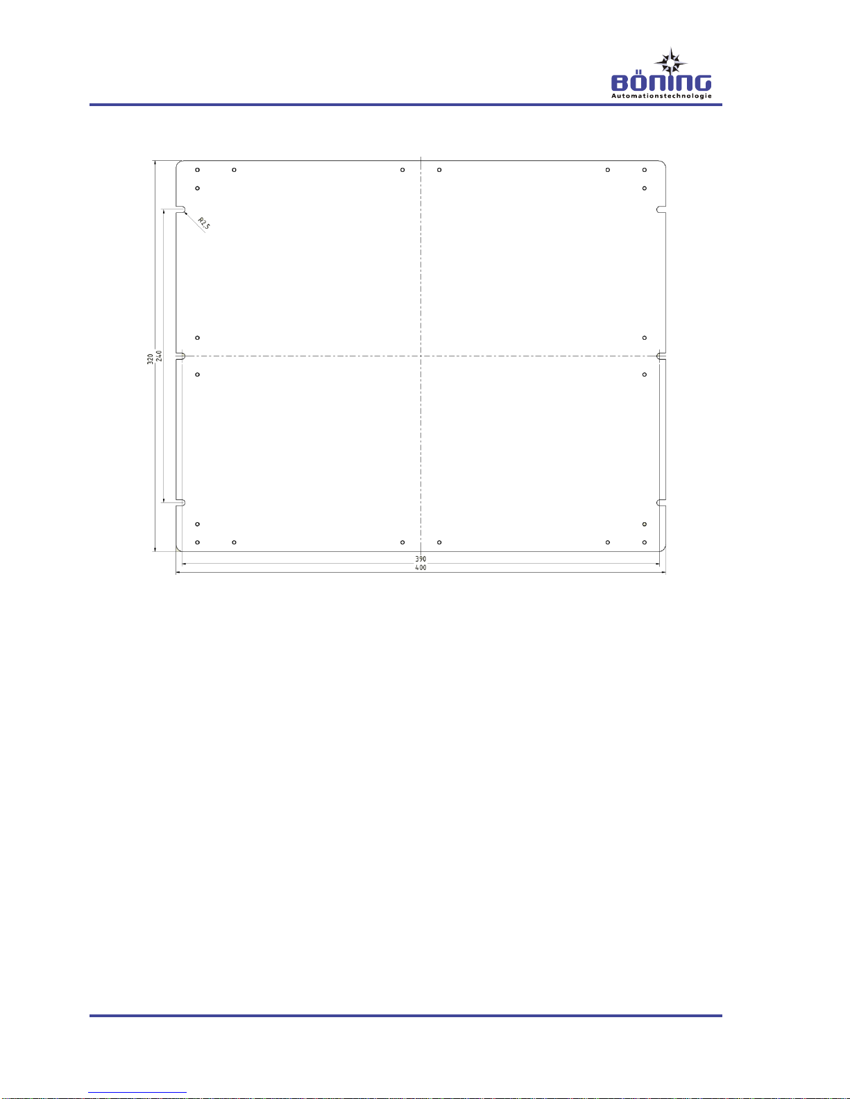
The device is mounted with six M4 screws.
All device connections are pluggable and have been led to the de-
vice front, making it possible to install the device quickly and safe-
ly. The device’s frontside protection class is IP 20.
The elimination of mechanically movable components, such as
hard drives, renders the device impact resistant.
Specially developed for use on board of ships, the box is complete-
ly maintenance free.

AHD 1200 Embedded PC
Structure and Function
14 V1
3.3 Device Electronics
The Embedded PC AHD 1200’s central unit is a 1.6 GH dual core
microprocessor that reads all incoming data and requests in the
supported protocols, providing all required information via a redun-
dant CAN bus in the ship system.
All necessary data can be stored on a 4GB flash disk.
The Embedded PC AHD 1200 includes an internal voltage control
which secures the required internal supply voltage. Therefore, the
device’s supply voltage fed by the external distribution can vary
from 18 V DC to 32 V DC (24 V DC +30%/-25%).
For increased operational safety, all communications interfaces are
galvanically isolated from one another.
3.4 Interfaces
6 interfaces to the CAN bus integrate the device into the ship sys-
tem. With the Universal CAN Converter AHD-UCC and the Proto-
col Converter Modbus AHD-UIC, additional protocols can be read
via the SAS protocol used.
CAN interfaces 5 and 6 are intended for the remote bus, which
provides commands for selecting video sources and controlling the
displays from e.g. the display control units AHD-DRM R and AHD-
DRM T.
The integrated RS232 interface can be used to connect e.g. a GPS
receiver.
The video IN port (BNC, coupling) receives data from an external
video source, e.g. a camera, for viewing on a display connected to
the AHD 1200’s DVI OUT output.
The VGA interface receives data from an external video source for
viewing on a display connected to the AHD 1200’s DVI OUT out-
put.
The DVI IN interface receives data from an external video source,
e.g. radar or electronic sea chart (ECDIS), for viewing on displays
connected to the AHD 1200’s DVI OUT output.
The DVI OUT interface transmits video data for output on a con-
nected display. The maximum resolution is 1024 x 768 pixels
(XGA) or 1080 x 1024 pixels (SXGA).
Data from the video sources connected to the Video IN, VGA and
DVI IN interfaces or video data provided by the AHD 1200 can be
sent from this interface.
CAN-Bus
RS232
Video IN
VGA
DVI IN
DVI OUT

AHD 1200 Embedded PC
Structure and Function
V1 15
These interfaces are used for connecting e.g. an AHD-DPU 9,
AHD-WNL, or a printer.
These interfaces allow for connecting external storage media, a
mouse, or a keyboard for operating the displays.
The four optocoupler inputs are primarily used for accepting ac-
knowledge requests.
The five relay outputs are primarily used for switching external
alarm indicators.
3.5 Electronic Data Processing
The Embedded PC AHD 1200 reads the ship data via the vessel’s
CAN bus, processes them, and makes them available via the CAN
bus to other devices, such as displays.
During the configuration process with the configuration software
AHD-DeviceConfig, basic properties for the visualization of ship
data, their processing, and data transmission via the AHD 1200 are
configured.
When configuring the display of values and statuses, the languag-
es used for controlling the ship are set up. Furthermore, the availa-
ble units with their necessary conversions, texts for displaying sta-
tuses and formats for displaying numbers, date and time informa-
tion are set up for viewing. These can be combined for selecting
country specific display settings.
When configuring data processing, the properties of the captured
system buses, devices, and their inputs and outputs are set up.
During the configuration of the system buses, their functions (ship
alarm system, engine monitoring, watch standby system and con-
trol (conning)) are also set up. Furthermore, basic settings for trig-
gering alarms, their viewing on displays, and the activation of event
log entries are configured.
During the configuration of the devices existing in the system bus-
es, their properties as well as the motor protocols used (MTU BR
2000, MTU BR 4000, MTU Serial, SAE J1939, NMEA 0183), and
among others, basic settings for triggering and viewing alarms on
displays are set up.
Accordingly, channel types (binary, analog) are set up when confi-
guring the physical and virtual channels. With both types, the
channel’s presentation on the displays, among other things, can be
configured. With analog channels, detected sensor values, their
conversion into physical measurands, as well as alarm triggers and
sensor errors can be configured. Channels can be combined into
groups, e.g. for group alarms.
Channel and group values can be combined for user defined func-
tions and can be used for controlling e.g. relay outputs. The availa-
ble functions encompass common mathematical calculations and
LAN
USB (Coupling A)
Opto-IN
Relay-OUT

AHD 1200 Embedded PC
Structure and Function
16 V1
special functions to use the AHD 1200 for monitoring and control-
ling ships.
Furthermore, control devices (receiver), interfaces, and relay out-
puts, are configured in the configuration.
TIP!
More information for configuring the AHD 1200 with
AHD-DeviceConfig can be found in the correspond-
ing configuration manual, which is available from
the manufacturer upon request.
TIP!
The configuration that has been set up with AHD-
DeviceConfig and stored in the device cannot be
changed e.g. from the vessel’s displays when the
device is running. You can only select preconfi-
gured settings from the ship displays.
Please contact the manufacturer or an authorized
representative, if it is necessary to change the con-
figuration.
3.6 Configuration
When configuring the AHD 1200, one must distinguish between
two configuration types:
–System configuration with AHD-DeviceConfig
–Visualization configuration with AHD Display Designer
During the ship’s system configuration with AHD-DeviceConfig, the
AHD 1200’s integration into the ship’s system is configured.
Among others, this process determines how ship data are
processed and how alarms are triggered and processed. In addi-
tion, basic settings, such as languages, units, and the presentation
of values and statuses on the ship displays are set up.
The configuration with AHD Display Designer determines how
measured values, statuses, and operating elements for controlling
the ship are rendered on suitable displays.
More information for configuring the device with AHD-DeviceConfig
can be found in the AHD-DeviceConfig operation manual and the
device’s configuration instructions.

AHD 1200 Embedded PC
Technical Information
V1 17
4 Technical Information
4.1 Technical Data AHD 1200
Description
Value/Unit/Type
General Data
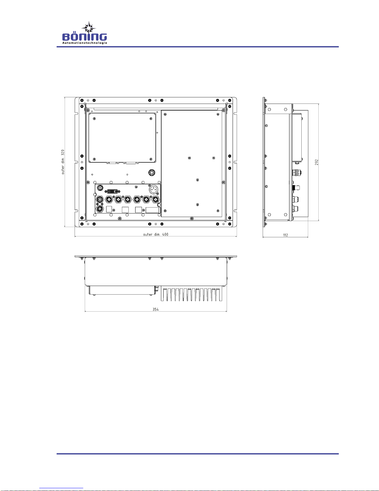
Dimensions, W x H x D
400 x 320 x 112mm
Panel Cutout, W x H
354 x 292mm
Req. Installation Depth
min. 130 mm (maintain a mini-
mum distance of 70mm between
cooling units and a wall when
installing the device)
Weight
appr. 10 kg
Environmental Data
Operating Temperature
-30°C…+55°C (-30°C…70°C at
an interior console temperature
of +45°C)
Storage Temperature
-30°C…+70°C
Protection Class
IP 20
Electrical Data
Power Supply
24VDC (+30% / -25%)
Performance
appr. 45W (24VDC)
Computer
Processor
1.6 GHz Dual Core
RAM
4GB
Flash Disk (SSD)
4GB
Operating System
Windows®XP Embedded

AHD 1200 Embedded PC
Technical Information
18 V1
Interfaces
6 x CAN (DeviceNet, 5-pin, Lum-
berg connector)
1 x RS232 (Sub-D, 9-pin, plug)
2 x LAN (coupling, RJ45,
10/100MBit)
2 x USB (coupling, A)
1 x Video IN (50Hz, composite
PAL, BNC, coupling)
1 x VGA (Sub-D, 15-pin, plug)
1 DVI IN (DVI-D, coupling)
1 DVI OUT (DVI-D, coupling)
4 x Opto-IN (Optocoupler, Lum-
berg, 8-pin, coupling)
5 x Relay-OUT (Relay, Lumberg,
8-pin, plug)
Resolution
DVI OUT
1024 x 768 pixels (max., XGA)
1280 x 1024 pixels (max., SXGA)
Classifications
In Progress
GL, DNV, LR, BV, DNV, ABS,
RMRS, RINA, CRS
4.2 Name Plate
The Embedded PC AHD 1200’s name plate is located on the de-
vice front and contains the following information:
Model designation of the unit (in the top section of the cover
plate)
Serial number (may be on separate label) and power supply
Manufacturer (may be on separate label) and CE marking
AHD 1200 Embedded PC
Technical Information
V1 19
4.3 Dimensions
4.3.1 Device Dimensions
AHD 1200 Embedded PC
Technical Information
20 V1
4.3.2 Drill Holes
Table of contents


