B-PWR PAFB-X Manual
I N S - P A F B X _ EN I n s t r u c t i o n G u i d e : F r o n t B u m p e r P a g e 1 | 11
Thank you for choosing a B-PWR product, designed by passionate riders who focus on what users really need.
1. SAFETY INSTRUCTIONS
To avoid any unfortunate situations, we recommend that you get to know how your modified vehicle handles before using it in extreme
conditions.
Read all the instructions carefully before installing this product.
If you do not have the tools or technical knowledge needed to ensure proper installation, have the product installed by an authorized
dealer.
It is essential that you follow the installation procedures, possess general mechanical knowledge and use appropriate tools to
ensure a safe and reliable installation.
Improper use or installation of the product, or any modifications made to adapt the product for use in a context other than that for
which it was intended, voids the warranty and may result in SERIOUS INJURIES.
B-PWR and all its affiliated companies, as well as its suppliers and distributors, are not responsible for any consequences
whatsoever resulting from an incorrect installation or an improper use of the product.
This guide provides detailed instructions for installing the product.
PAFB-X
Polaris snowmobile Axys platform
For safety reasons, this kit needs to be installed by a person with general mechanical knowledge using the proper tools.
The illustrations in this document indicate the typical structure of the various assemblies. It is therefore possible that they do not
represent the exact form of the parts or the manufacturing details. These illustrations are intended to identify parts that perform an
identical or similar function.
I N S - P A F B X _ EN I n s t r u c t i o n G u i d e : F r o n t B u m p e r P a g e 2 | 11
2. REQUIRED TOOLS
TOOLS
T1
10 mm Socket
T4
Ratchet
T2
10 mm Wrench Key
T5
Torque Wrench
T3
Drill Bit 1/4"
T6
T30 Torx Socket
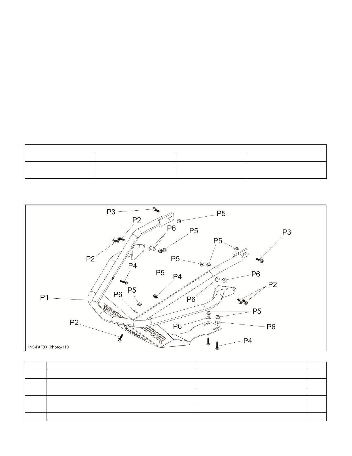
3. PARTS
ITEM
DESCRIPTION
PART NUMBER
QTY
P1
Front Bumper
PAFB-X-BL-C
1
P2
M6 X 20 mm Hexagonal Flanged Screw
207662054B
5
P3
M6 X 25 mm Hexagonal Flanged Screw
999100024
2
P4
M6 X 25 Rounded Head Screw
250000758B
4
P5
M6 Nylon Lock Nut
233261494B
9
P6
M6 Washer
999100020
7

I N S - P A F B X _ EN I n s t r u c t i o n G u i d e : F r o n t B u m p e r P a g e 3 | 11
4. VEHICLE PREPARATION
Read all the instructions carefully before installing the product.
Make sure you have enough space to work properly.
Make sure to have the required tools.
Note:Unlessdifferencesoccurbetweenlefthand(LH)and righthand(RH)sides,theprocedures areshown for onlyonesideofthe
vehicle.Repeatforotherside.Rightandleftsidesaredefinedaswhensittingonthevehicle.
4.1 Remove side panel with two (2) locking clip and a strap.

I N S - P A F B X _ EN I n s t r u c t i o n G u i d e : F r o n t B u m p e r P a g e 4 | 11
4.2 Disconnect connectors attached to center panel.
4.3 Disengage two (2) locking clip of center panel.
4.4 Remove center panel.

I N S - P A F B X _ EN I n s t r u c t i o n G u i d e : F r o n t B u m p e r P a g e 5 | 11
4.5 Remove screw, nut and keep ground in a visible position for reinstallation.
4.6 Remove two (2) screws securing bumper using T30 Torx socket [T6].
4.7 Remove screw and nut that secure exhaust and front of bumper.

I N S - P A F B X _ EN I n s t r u c t i o n G u i d e : F r o n t B u m p e r P a g e 6 | 11
4.8 Remove and keep exhaust retaining spring.
4.9 Remove screw, nut and keep exhaust retaining spring plate.
1- Exhaust retaining spring plate

I N S - P A F B X _ EN I n s t r u c t i o n G u i d e : F r o n t B u m p e r P a g e 7 | 11
4.10 Drill two (2) rivets under vehicle with drill bit 1/4" [T3] as shown.
4.11 Remove bumper.
5. INSTRUCTIONS
5.1 Position front bumper [P1] with a M6 X 25 mm hexagonal flanged screw [P3], M6 nylon lock nut [P5] and ground as shown.
Hand tighten only.
1- Ground located on LH side

I N S - P A F B X _ EN I n s t r u c t i o n G u i d e : F r o n t B u m p e r P a g e 8 | 11
5.2 Locate front bumper [P1] with a M6 X 25 mm hexagonal flanged screw [P3], M6 nylon lock nut [P5] and exhaust retaining spring
plate as shown. Hand tighten only.
1- Exhaust retaining spring plate
5.3 Secure front bumper [P1] with two (2) M6 X 25 rounded head screw [P4] using T30 Torx socket [T6].
1- LH side shown
TIGHTENING TORQUE
M6 X 25 rounded head screw [P4]
10 N•m ± 2 N•m

I N S - P A F B X _ EN I n s t r u c t i o n G u i d e : F r o n t B u m p e r P a g e 9 | 11
5.4 Tighten to specification two (2) M6 nylon lock nut [P5] with two (2) 10 mm wrench key [T2] as shown.
TIGHTENING TORQUE
M6 Nylon Lock Nut [P5]
10 N•m ± 2 N•m
5.5 Secure front bumper [P1] with a M6 X 20 mm hexagonal flanged screw [P2] M6 nylon lock nut [P5] and M6 washer [P6] as shown.
TIGHTENING TORQUE
M6 Nylon Lock Nut [P5]
10 N•m ± 2 N•m

I N S - P A F B X _ EN I n s t r u c t i o n G u i d e : F r o n t B u m p e r P a g e 10 | 11
5.6 Install exhaust retaining spring previously removed.
5.7 Drill four (4) holes in front panel using front bumper [P1] as a template with a drill bit 1/4" [T3] as shown.
5.8 Secure front bumper [P1] with four (4) M6 X 20 mm hexagonal flanged screw [P2], M6 nylon lock nut [P5] and M6 washer [P6] as
shown.
TIGHTENING TORQUE
M6 nylon lock nut [P5]
10 N•m ± 2 N•m

I N S - P A F B X _ EN I n s t r u c t i o n G u i d e : F r o n t B u m p e r P a g e 11 | 11
5.9 Secure front bumper [P1] with two (2) M6 X 25 rounded head screw [P4], M6 nylon lock nut [P5] and M6 washer [P6] using T30
Torx socket [T6].
TIGHTENING TORQUE
M6 nylon lock nut [P5]
10 N•m ± 2 N•m
5.10 Here is final result of installation of assembly.
5.11 Install various panels in reverse sequence of removal procedure.
Note: Ensurethatpreviouslyremovedconnectionsareproperlymadeto centerpanel.
Table of contents
Other B-PWR Motorcycle Accessories manuals


