BöSha BS 67 Series User manual

Operating Instructions
BöSha GmbH + Co. KG · Industriegebiet Heidberg 10 · D - 59602 Rüthen
Ph.: ++49 - (0)2952 – 97091-0 · Fax: ++49 - (0)2952 – 97091-150 · Email: info@boesha.de ·
www.boesha.de
MU/26.04.2016 13:33:00/BS671.doc 26.04.2016 13:33:00
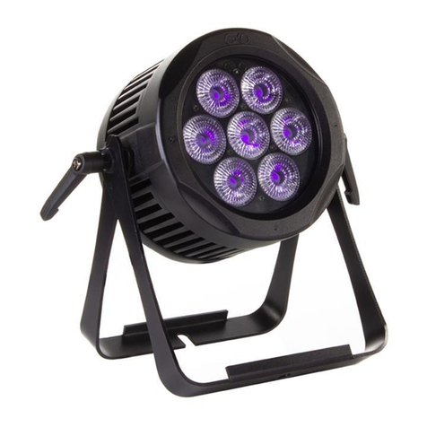
Projector BS 67...., BS 68.... und BS 69....
EC Type Examination Certificate:
IBExU 05 ATEX 1111
Type of Explosion Protection: I M2 EEx eq(d) I
II 2G EEx eq(d) IIC T4 / T3
II 2D T 80 °C IP 66
Degree of Enclosure Protection: IP 66
Ambient Temperature Range: - 20 °C to + 40 °C
Technical Specifications
Dimensions
Versions
with
metal frame lids
BS 671...
BS 672...
BS 673...
BS 674...
BS 675...
BS 676...
BS 677...
BS 678...
Length approx.
Width approx.
Height approx.
492 mm
400 mm
190 mm
650 mm
400 mm
160 mm
750 mm
400 mm
160 mm
Versions
with
glass / PC lids
BS 685...
BS 686...
BS 687...
BS 688...
BS 689...
BS 690...
BS 691...
BS 692...
BS 693...
Length approx.
Width approx.
Height approx.
516 mm
424 mm
180 mm
674 mm
424 mm
150 mm
774 mm
424 mm
150 mm
Electrical parameters
Type Rated voltage Frequency Lamp wattage Current consumption
approx.
BS 671
BS 672
BS 673
BS 673
BS 674
BS 674
BS 675
BS 676
BS 677
BS 678
230 V
0-50/60 Hz
3 x 36 W
4 x 36 W
3 x 36 W
3 x 40 W
4 x 36 W
4 x 40 W
3 x 55 W
4 x 55 W
3 x 80 W
4 x 80 W
0.47 A
0.63 A
0.47 A
0.52 A
0.63 A
0.70 A
0.72 A
0.96 A
1.04 A
1.39 A

Operating Instructions
BöSha GmbH + Co. KG · Industriegebiet Heidberg 10 · D - 59602 Rüthen
Ph.: ++49 - (0)2952 – 97091-0 · Fax: ++49 - (0)2952 – 97091-150 · Email: info@boesha.de ·
www.boesha.de
MU/26.04.2016 13:33:00/BS671.doc 26.04.2016 13:33:00
Type Rated voltage Frequency Lamp wattage Current consumption
approx.
BS 685
BS 685
BS 686
BS 686
BS 687
BS 687
BS 688
BS 688
BS 689
BS 690
BS 691
BS 692
BS 693
230 V
0-50/60 Hz
3 x 36 W
3 x 40 W
4 x 36 W
4 x 40 W
3 x 36 W
3 x 40 W
4 x 36 W
4 x 40 W
3 x 55 W
4 x 55 W
3 x 80 W
4 x 80 W
8 x 18 W
0.47 A
0.52 A
0.63 A
0.70 A
0.47 A
0.52 A
0.63 A
0.70 A
0.72 A
0.96 A
1.04 A
1.39 A
0.63 A
Installation and connection
The projectors of type BS 67.., BS 68.. and BS 69.. may be installed in any position. Mounting straps being
attached to the enclosure serve as mounting aid for wall mounting, or eyebolts for suspension from a ceiling.
Beneath the reflector, there is the terminal compartment containing a terminal board, a protective ground
conductor terminal and a terminal diagram. The mains power supply line is fed through a cable entry into
the terminal compartment and is connected to the terminal board and the ground conductor terminal
according to the enclosed terminal diagram. In case the projectors are equipped with plug and socket
connectors there is no terminal board, and the internal wiring is already installed by the manufacturer.
ATTENTION! If the enclosure is equipped with threaded sleeves these will have thread M 36 x 1.5!
Starting operation
Before starting operation of luminaires with cable entries care must be taken that the terminals of the
connecting cables are properly tightened and the enclosure of the projector is tightly closed (check the
screws in the lid and the cable entries or the plug and socket connectors).
Repair
Defect illuminants (customary four-pin compact fluorescent lamps with socket 2 G 11 – 36, 40, 55 or 80 W
– or customary bi-pin fluorescent tubes with G 13 sockets – 18 W) may be exchanged by the operator
himself, under the condition that the installation instructions are regarded. For this purpose versions without
micro switches have to be completely de-energized; for versions with micro switches this is not required as
the lamp holders become de-energized when the lid is opened (see warning label on the housing lid or – in
case there is a micro switch – on the reflector: Do Not Open While Energized!). Regard has also to be paid

Operating Instructions
BöSha GmbH + Co. KG · Industriegebiet Heidberg 10 · D - 59602 Rüthen
Ph.: ++49 - (0)2952 – 97091-0 · Fax: ++49 - (0)2952 – 97091-150 · Email: info@boesha.de ·
www.boesha.de
MU/26.04.2016 13:33:00/BS671.doc 26.04.2016 13:33:00
to the heat generation of the projector, so that it may be necessary to wait for a couple of minutes before the
projector is opened.
To open the projector the screws of the lid have to be undone. Now the illuminants are accessible and can be
exchanged. When installing ensure a firm fit of the lamp holders. Lamp holders with defect contact elements
have to be exchanged immediately.
Repairs of explosion-proof projectors may only be carried out by authorized personnel and by using original
spare parts of the manufacturer.
Special conditions have to be observed, if applicable.
When installing electrical equipment in potentially explosive atmospheres EN 60079-14 has to be complied
with.
ATTENTION !!!
Before starting operation store the projectors in a dry place, protect against moisture!
This manual suits for next models
19
Table of contents
