STUDIODUE CITYCOLOR Series User manual
User’s and operator’s manual for art. 0503 and 0505
IP•54
INTERNATIONAL PATENT WO99/40361

Safety informations
Informazioni di sicurezza .................................................................................................................. page 1
Technical features
Caratteristiche tecniche .................................................................................................................... page 3
Lamp installation and replacement
installazione e sostituzione lampada ............................................................................................... page 4
Connection to the main power
Connessione alla rete ....................................................................................................................... page 5
DMX signal connection (IP54) /DMX terminal line
Connessione segnale DMX (IP54) /Terminale di linea DMX .......................................................... page 5
Installation of the dust proof filters (IP54)
Installazione e rimozione dei filtri antipolvere (IP54) ...................................................................... page 6
Example of connection DMX controller-spot
Esempio di collegamento centralina-fari ......................................................................................... page 7
DMX listing
Lista valori DMX ............................................................................................................................... page 8
Setup
Settaggio ........................................................................................................................................... page 9
Description of the games
descrizione dei giochi ....................................................................................................................... page 10
Electric diagrams
Schemi elettrici.................................................................................................................................. page 11
INDEX • INDICE
ita
eng
WARNING
!
INFORMAZIONI DI SICUREZZA
LEGGERE ATTENTAMENTE TUTTI GLI AVVERTIMENTI PRIMADICOMPIERE QUALUNQUEOPERAZIONE SU QUESTO
APPARECCHIO. ISTRUZIONI PER PREVENIRE LESIONI ODANNI DOVUTI AL FUOCO, ALLE SCOSSEELETTRICHE,
AI RAGGIULTRA
VIOLETTI ED AI RISCHIMECCANICI.
•PROTEZIONE CONTRO IL FUOCO
1) Questo apparecchio è progettato per funzionare esclusivamente con la lampada:
(1800) Philips MHN/SA1800W e (2500) Philips MSA/DE2500W
NON USARE ASSOLUTAMENTE ALTRI TIPI DI LAMPADA!
2) Mantenere la distanza minima di 0.5 metri da pareti ed altre superfici infiammabili.
3) Mantenere la distanza minima di 2.0metri dagli oggetti illuminati.
4) Sostituire i fusibili solo con altri dello stesso tipo e valore.
5) Non installare il faro vicino fonti di calore. Non appoggiare il cavo di connessione sul faro quando questo è caldo.
•PROTEZIONE CONTRO SCOSSE ELETTRICHE
1) Questo apparecchio necessita di messa a terra.
2) Apparecchio di Classe I. Il conduttore di protezione deve far parte del cavo di alimentazione.
3) Disconnettere l’alimentazione prima di sostituire la lampada o aprire l’apparecchio (personale di servizio).
•PROTEZIONE CONTRO RISCHI MECCANICI
1) Usare la catena di sicurezza supplementare quando installate il faro.
2) Rischio di esplosione con lampada calda. Non aprire l’apparecchio per 300 secondi dopo lo spegnimento.
3) La temperatura dell’apparecchio può raggiungere 100°C. Attendere circa 5 minuti prima di operare sul faro.
4) Sostituire la lampada se è danneggiata o deformata a causa del calore.
•PROTEZIONE CONTRO RISCHI DA RADIAZIONE UV
1) Non accendere l’apparecchio senza lo schermo protettivo o se le lenti o i filtri per l’ultravioletto sono danneggiate.
2) Gli schermi di protezione, le lenti, o i filtri ultravioletti, devono essere sostituiti se sono visibilmente danneggiati e se la loro
efficacia è stata ridotta, per esempio, da fessure o incisioni profonde.
3) Non guardare direttamente la lampada quando questa è accesa.
IMPORTANTE
!
SAFETY INFORMATION
READ ALL CAUTIONS AND WARNINGS PRIOR TO OPERATE THIS EQUIPMENT.
INSTRUCTION TO PREVENT INJURY OR DAMAGEDUETO ELECTRIC SHOCK, FIRE, MECHANICAL HAZARDS AND
UV RADIATION HAZARDS.
•PROTECTION AGAINTS FIRE
1)This equipment is designed for use with the following lamps only:
(1800) Philips MHN/SA1800W e (2500) Philips MSA/DE2500W
DO NOT USE ANY OTHER TYPE OF LAMP!
2) Maintain minimum distance of 0.5 meter from walls or any other type flammable surfaces.
3) Maintain minimum distance of 2.0meter to lighted objects .
4) Replace fuses only with the specified type and rating.
5) Do not install the spot close to heat sources. Do not lay the connection cable on the spot when it is warm.
•PROTECTION AGAINST ELECTRIC SHOCK
1) This equipment must be earthed.
2) Class Iequipment. The power supply cord includes a protective earthing conductor as part of the cord.
3) Disconnect power before installing the lamp or servicing (service personnel).
•PROTECTION AGAINST MECHANICAL HAZARDS
1) Use secondary safety chain when fixing this equipment.
2) Hot lamp explosion hazard. Do not open the equipment for 300 seconds after switching off.
3) Equipment surface may reach temperature up to 100°C. Allow about five minutes before handling.
4) Replace the lamp if it is damaged or thermally deformed.
•PROTECTION AGAINST UV RADIATION HAZARDS
1) Do not start on this equipment without lamp enclosure or if the protection screens, or ultraviolets screens are damaged.
2) The protection screens, the lenses, or the ultraviolet filters must be replaced if they are visibly damaged and their effectiveness
has been reduced, for example, by cracks or deep scratches.
3) Do not look directly at the lamp while lamp is on.
... 1 ...

INTRODUZIONE
Vi ringraziamo per l’utilizzo del nostro proiettore flood CityColor 1800/2500.
Il proiettore CityColor è realizzato con un sistema ottico brevettato estrememente efficace (patente n. W099/40361) la sua capa-
cità di generare una luce diffusa e potente ed innumerevoli colori ed ombre contribuiscono a realizzare coreografie incredibili su
qualsiasi superfice.
Il CityColor viene realizzato nelle seguenti versioni:
• Art. 0505 CITYCOLOR CC/2500W
• Art. 0503 CITYCOLOR CC/1800W
Il protocollo di ingresso è il DMX 512. Per il pilotaggio del CityColor raccomandiamo l’utilizzazione delle nostre centraline Control
Show 512, Fancy, Easy Control o Control 5 che sono in grado di pilotarlo in modo ottimale.
Per ottenere il meglio delle prestazioni ed un corretto funzionamento negli anni di questa unità, Vi consigliamo di leggere attenta-
mente questo manuale prima di collegarla e metterla in uso. In questo modo acquisirete familiarità con i suoi comandi e collegamenti
affinché possiate utilizzarla facilmente.
VOSTRA REFERENZA
Citate il numero del modello e di serie ogni volta che Vi rivolgete al vostro rivenditore per informazioni o assistenza.
CONFEZIONE BASE
La confezione base del proiettore CityColor contiene:
• Proiettore
• Lampade (su richiesta)
• Connettore di alimentazione
• Manuale d’uso
• Garanzia Studio Due
INTRODUCTION
Thank you for using our flood projector CityColor 1800/2500.
The CityColor projects, thanks to an extremely efficient optic system (patent n. WO99/40361), a powerful light beam which can create
numberless color shades. Its performances, in terms of luminousity and lighted surfaces, can reach incredible levels.
The CityColor CC comes in the following versions:
• Art. 0505 CITYCOLOR CC/2500W
• Art. 0503 CITYCOLOR CC/1800W
The CityColor can work in automatic mode or in synchro mode, otherwise may be controlled by 8 bit DMX controllers
The input protocol is the DMX 512. To drive the CityColor we suggest to use either our controller DMX Control Spot, the
Control Show 512 the Easy Control the Fancy or the Control 5.
To make the most of its possibilites and for a correct functioning of this unit in the years to come, we suggest you to read carefully
this manual before connecting or putting the spot into use. By doing so you will gain experience with its commands and connections
and you will be easily able to use it.
YOUR REFERENCE
Please always mention the serial number and model every time you address the seller for any information or assistance
BASIC KIT
The basic kit of the CitiColor flood projector contains:
• Projector
• Power connector
• User’s Manual
• Studio Due warranty
Controllate che l’apparecchio non abbia subìto alcun danno durante il trasporto.
Se avesse subìto dei danni o se non dovesse funzionare, rivolgetevi al vostro rivenditore. Se l’apparecchio vi è
stato spedito direttamente, rivolgetevi immediatamente alla ditta di trasporto. Solo il destinatario (la persona o
ditta ricevente l’apparecchio) può reclamare per questo tipo di danni.
IMPORTANTE
!
Check that the spot has not been damaged during transport. If it has been damaged or it does not work, address
the seller. Whether the spot has been shipped to you directly, please contact the shipping company.
Only the consignee (person or company) can claim for these damages.
WARNING
!
eng
ita
... 2 ...
Available on request:
•art. 0505/a: barndoor to define illuminated surface
•art. 0002/a: XLR 3pin male IP54connectors
•art. 0002/b: XLR 3pin female IP54connectors
•Lamp
Accessori a richiesta:
•art. 0505/a: sagomatore luce in metallo
•art. 0002/a: XLR 3pin connettore maschio IP54
•art. 0002/b: XLR 3pin connettore femmina IP54
•Lampada
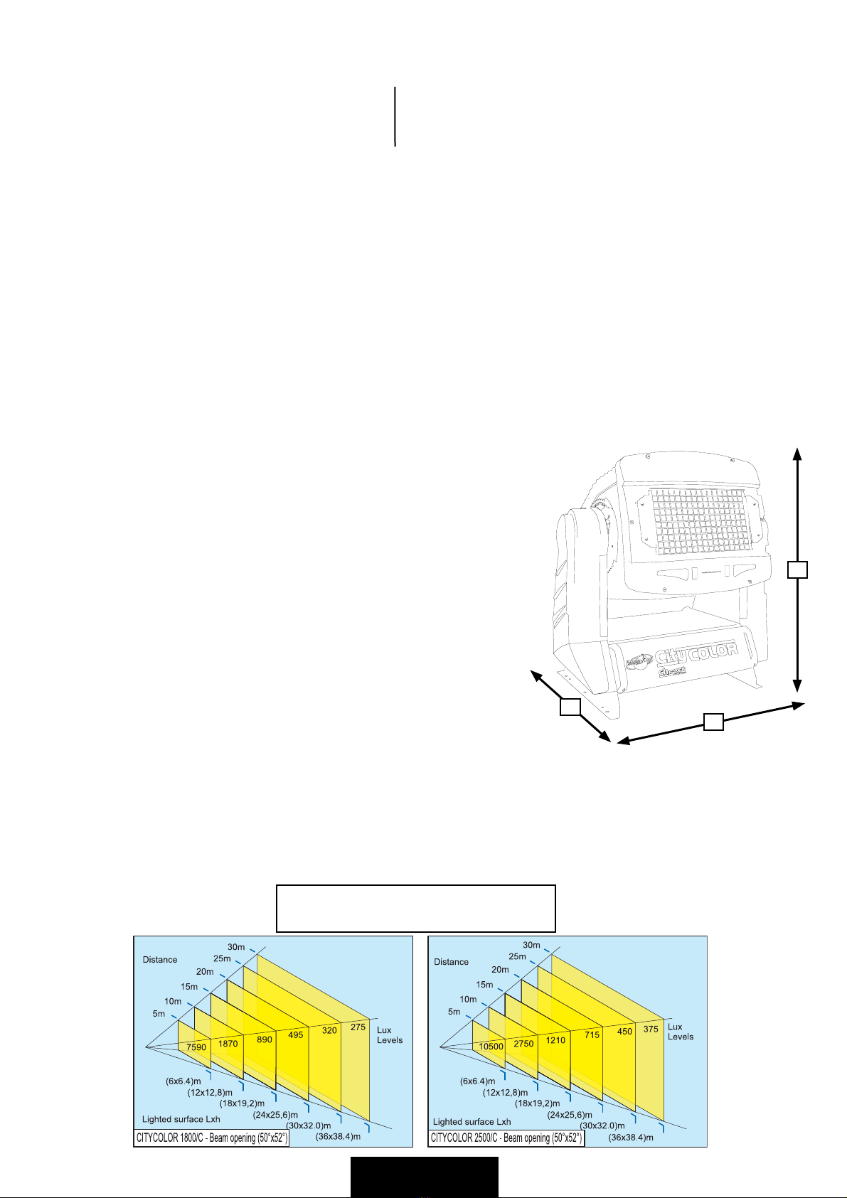
D
W
H
PHOTOMETRIC PARAMETERS
PARAMETRI FOTOMETRICI
TECHNICAL FEATURES / CARATTERISTICHE TECNICHE
•LAMPS /LAMPADE
MHN/SA1800W PHILIPS (art. 0503)
Color temperature /Temperatura colore: 5.600°K
Lamp life /Vita della lampada: 2.500 hours /ore
Luminous flux /Flusso luminoso: 180.000 lm
•OPTIC COLOR SYSTEM /SISTEMACOLORI
Full CYM color mixing, unlimited variety of colours and shades. High resolution stepper motors.
Shutter + dimmer. The color changer can be drived with 4 different speeds or in real time.
Miscelazione totale colori CYM, illimitata varietà di colori e sfumature. Motori passo-passo ad alta risoluzione
Oscuratore + dimmer. Il cambiacolori può lavorare sia con 4velocità selezionabili che il real time.
•BEAM ANGLE /ANGOLO DELLA LUCE: (50% intensity) 50°x52°
•CONTROL INPUT /SEGNALE DICONTROLLO
Standard interface: RS-485; opto-couplet input.
Protocol: USITT DMX 512
6or 7 channels
•SETUP AND CONFIGURATION /SETTAGGIO ECONFIGURAZIONE
On the control panel with menu and keys
Tramite pannellino di controllo
•AUTOMODE /MODOAUTOMATICO
Stand-alone control: auto mode function master/slave (synchro mode) with 64 programs
Selezionabile in master/slave (sincronizzato) con 64 programmi differenti
•IP RATE /PROTEZIONE IP: IP 54(whit filter supplied/con filtri antipolvere)
•POWER SUPPLY /ALIMENTAZIONE (1800W): (art. 0503) magnetic ballast
Rated voltage /Tensione di lavoro: 230V/50Hz
On request /Arichiesta: 200V/50Hz; 208V/60Hz; 230V/60Hz; 240V/50Hz
Rated current /Corrente assorbita: 10A
Rated power /Potenza assorbita: 2300W
•POWER SUPPLY /ALIMENTAZIONE (2500W): (art. 0505) magnetic ballast
Rated voltage /Tensione di lavoro: 230V/50Hz
On request /Arichiesta: 200V/50Hz; 208V/60Hz; 230V/60Hz; 240V/50Hz
Rated current /Corrente assorbita: 13A
Rated power /Potenza assorbita: 3000W
•POWER FACTOR CORRECTOR /FATTORE DICORREZIONE: built-in cos Ø 0.9
•DMX CHANNELS /CANALI DMX
ch1= motors speed /velocità motori
ch2 = cyan /ciano
ch3= yellow /giallo
ch4= magenta /magenta
•DIMENSIONS /DIMENSIONI (wxdxh)
mm 790x580x760 (max 870)
•WEIGHT /PESO
art. 0503 (1800w): 64,5 kgs. net
art. 0505 (2500w): 70,9kgs. net
... 3 ...
MSA/DE2500W PHILIPS (art. 0505)
Color temperature /Temperatura colore: 6.000°K
Lamp life /Vita della lampada: 2.000 hours /ore
Luminous flux /Flusso luminoso: 260.000 lm
ch5 = dimmer
ch6= basic colors + rainbow /colori base + rainbow
ch7 = remote reset+lamp off /reset + spegnimento lampada da DMX

... 4 ...
INSTALLATION OF THE DISCHARGE LAMP / INSTALLAZIONE DELLA LAMPADA A SCARICA (art. 0505 - 0503)
1) Disconnect power before lamp’ s replacement or servicing. Wear gloves and goggles (service personnel).
Scollegare l'alimentazione ed indossare dei guanti di protezione (personale di servizio)
2) Remove completely the pommels (A) on the external rear lamp cover (G).
Rimuovere completamente i pomelli (A) del coperchio esterno posteriore (G)
3) Open the cover of the lamp room (G)
Aprire il coperchio del vano lampada (G)
4) Unscrew the screws (H) and open the lamp support plate (F).
Svitare le viti (H) ed aprire il supporto dell'ottica (F)
5) Remove the two lateral reflectors (C) on the optic group.
Rimuovere i due riflettori piani laterali dell'ottica (C)
6) Lift up the two lampholder (D).
Aprire i due blocca-lampada (D)
7) Install the new lamp or replace it. Taking care that protuberance of the bulb is set towards the reflector
Do not touch the quarz bulb with fingers. If this happenes, clean the bulb before use with dry cloth and alcohol.
Installare la nuova lampada, posizionare con cura la pretuberanza del bulbo verso il riflettore
Non toccare la parte in vetro della lampada, se dovesse accadere, pulire bene con alcol.
8) Put down the two upper lampholders (D)
Riposizionare i due blocca-lampada (D)
9) Connect the cables (E) to the two ends of the lamp
Connettere i cavi ai terminali dalla lampada (E).
10)Put in again the two lateral plane reflectors (C).
Rimontare i due riflettori piani laterali (C)
11)Close the lamp support plate (F) and the rear lamp cover (G) and screw again the two pommels (A) and hold them tightly.
Chiudere il supporto dell'ottica (F), richiudere il coperchio posteriore (G) e riavvitare i due pomelli (A) in modo ermetico.
In case of replacement of the lamp or maintenance, do not open the fixture unless 10 minutes
have passed from the switching off, this operation has to be done when the apparatus is
disconnected from the mains supply.
In caso di sostituzione della lampada, non aprire l'apparecchio prima di 10 minuti dopo lo spegnimento
per permettere il raffreddamento delle parti, in ogni caso scollegare sempre il cavo di alimentazione
WARNING
!
pict.1
A
G
H
F
pict.2
pict.3
F
pict.3a
C
C
D
E

... 5 ...
CORRECT USE OF DISCHARGE LAMPS
Start-up procedure
The start-up phase of a metal halide lamp is taken to be the period of time from ignition to the operating state, in which the lamp
reaches its rated electrical and photometric values.
This time is dependent on the type of lamp, the control gear used and the cooling conditions in the fixture. 80% of the “light” is
normally available after approximately 3minutes. After the lamp has been ignited (in its cold state), the filler components (mer-
cury, halides and rare earths) vaporise one after another. At the same time, the lamp voltage, electrical output and luminous flux
gradually increase until the reach their respective rated values.
ATTENTION:
If the lamp is switched off during the start-up phase, the filler components are deposited on the internal wall of the bulb and on
the electrodes: this can be seen as a dark, opaque coating and adversely effects ignition. In some rare cases, it may be impossible
to restart the lamp. According to the extent of damage, lamp life will be proportionally shorter.
eng
ita
CORRETTO USO DELLE LAMPADE A SCARICA
Processo di avviamento
L’avviamento di una lampada a vapori di alogenuri è il tempo che intercorre dall’innesco al raggiungimento del regime, durante il
quale si raggiungono i valori elettrici e fotometrici nominali. Questo intervallo di tempo dipende dal tipo di lampada, dall’alimentatore
e non ultimo dalle condizioni di raffreddamento dell’apparecchio di impiego.
Normalmente si ottiene l’ 80% della luce dopo circa 3minuti.
Ad accensione avvenuta (partendo da lampada fredda) le sostanze di riempimento (mercurio, alogenuri, metalli delle terre rare)
evaporano in successione.
In questa situazione crescono a poco a poco la tensione di lampada, la potenza elettrica e il flusso luminoso fino al raggiungimento
del valore nominale.
ATTENZIONE:
Se la lampada viene spenta durante la fase di avviamento, sulla parete interna del bulbo e su gli elettrodi si depositano i componenti
di riempimento: per l’utente essi sono visibili come un deposito scuro non trasparente. Acausa di ciò il comportamento all’accen-
sione viene influenzato negativamente; in alcuni casi l’avviamento della lampada non è neppure più possibile. Aseconda dell’entità
di questo danno, si accorcia di più o di meno la durata della lampada.
CONNECTION TO THE MAIN POWER / CONNESSIONE ALLA RETE ELETTRICA
3PIN CONNECTOR (IP 67) FOR POWER INPUT
CONNETTORE A3POLI (IP 67) INGRESSOALIMENTAZIONE N= NEUTRAL
L= LIVE
= GROUND
CONDUCTOR SIZES / SEZIONE CONDUTTORE
(length / lunghezza < 20mt.)
MAINS VOLTAGECROSS SELECTIONAL AREAS
230V3X2,5 mm2(minimum)
CIRCUIT BREAKER / INTERRUTTORE
MAINS VOLTAGEInId
230V32A0,03A
Studio Due CITYCOLOR CC art. 0503
Keep at least a distance of 0,5 mts between the apparatus and
inflammable surface nearby.
Disconnect the unit from power before servicing.
230Vac; 10A - 50Hz SN QC
!
DMX CONNECTION (IP54 / COLLEGAMENTO DMX (IP54)
The connection of the DMX signal to the CityColor must be made by using the signal input XLR
3pin connectors which are located on the control panel of the fixture.
To ensure the IP54 rate you must connect the DMX cable inside the base. Use the given cables
fixing (pict.1) and connect by following the cables numbering (pict.2).
La connessione del segnale DMX con il CityColor deve essere effettuata tramite i connettori
d'ingresso segnale XLR3 pin presenti sul pannello laterale della base dell'apparecchio.
Per assicurare un IP rate 54 è necessario connettere direttamente il cavo DMX internamente
alla base utilizzando gli appositi passacavo (pict.1) ed effettuare le connessioni rispettando
la numerazione dei cavi (pict.2)
pict. 2pict. 1
Input Output Input Terminal
resistor
LASTSPOT
Ø 6mm
DMX CONNECTION
BROWN= SHIELD
RED= -DMX
ORANGE= +DMX
... 6 ...
WARNING
!
IP RATE
The declared IP rate of the CityColor comes supported at these conditions:
• the installation of the fixture on a wide and stable surface
• the air cooling input and output are located on the base of the side-shell,
it is not possible to install the fixture outdoor with the ballast upwards
• you must use the filter supplied with the basic kit for the IP RATE 54
The CityColor has a IP rate 44 without filters installed and an IP RATE 54 with filters installed.
You must use the filters in critical working conditions and, normally, when the fixture works outdoor.
You must remove the filters when the ambient temperature is over 35°C.
You must regularly clean the filters to allow the correct cooling of the fixture.
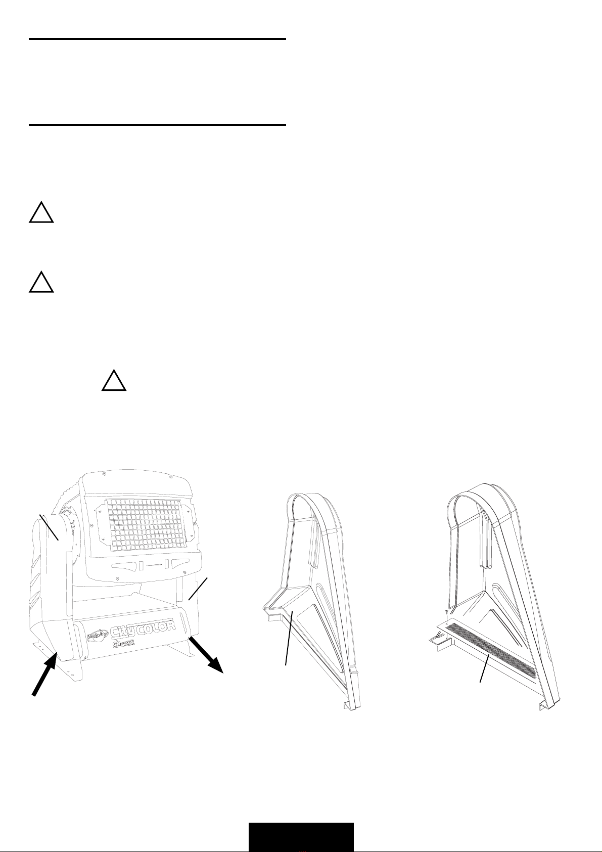
You must remove the two side protective shells(A). The two filters must be assembled
on the side protective shells (B).
Pay attention to the installation: dust proof filters must stick correctly to prevent the entrance of the
dust. You must control that the two filters completely cover the overall of the air entrance.
You must operate with power supply disconnected from the fixture
Operare a faro spento e scollegato dalla rete elettrica
IMPORTANTE
!
INSTALLATION OF THE DUST PROOF FILTERS / INSTALLAZIONE E RIMOZIONE FILTRI ANTIPOLVERE
IP RATE
L'IP rate dichiarato del CityColor viene rispettato a queste condizioni:
• installazione del faro su di una superficie sufficientemente ampia e stabile
• l'entrata e l'uscita dell'aria di raffreddamento avviene alla base dei due gusci laterali,
non è quindi possibile l'installazione del faro all'aperto con il ballast rivolto verso l'alto
• uso dei filtri antipolvere del KIT IP rate 54
eng
ita
Il CityColor ha un IP rate di 44 senza filtri antipolvere installati ed un IP rate di 54 con i filtri installati. L'uso dei
filtri è indispensabile in particolari condizioni di lavoro e normalmente quando il faro è insallato all'aperto.
E' indispensabile la rimozione dei filtri quando è presente una temperatura ambiente superiore ai 35°C.
E' indispensabile la regolare pulizia dei filtri per consentire il corretto raffreddamento del faro.
!
Rimuovere i due gusci di protezione laterali (A). I due filtri vanno montati sui gusci nella
parte inferiore (B)
A
B
Occorre porre molta attenzione a farli aderire correttamente per impedire l'entrata della polvere.
Controllare anche visivamente che i due filtri coprano completamente la superficie di entrata dell'aria.
A
A
Air cooling input
Air cooling output
Control Spot
Studio Due
Studio Due
R
CHANNEL 8/
10
CHANNEL 7/
9
CHANNEL 4CHANNEL 3CHANNEL 2CHANNEL 1
STANDBY
PROGRAM
FADIN G
AUTO
MUSIC
MANUAL STEPS
STEP TIME FADING
789
456
123
0
SPOT MORE ALL NONE
TILTPANCOPYCLEARCOPYDELETEINSERT
SELECT SPOTS SPOTS SPOTS
INVERTINVERTPROGRAMPROGRAMSTEPSTEPSTEP
ENTEREXIT
PROGRAMMING
SPOTS FUNCTIONS
PROGRAMS SPOTS STEPS
SELECT
PLAY
... 7 ...
DMX1output/linea uscita DMX1
DMX2 output/linea uscita DMX2
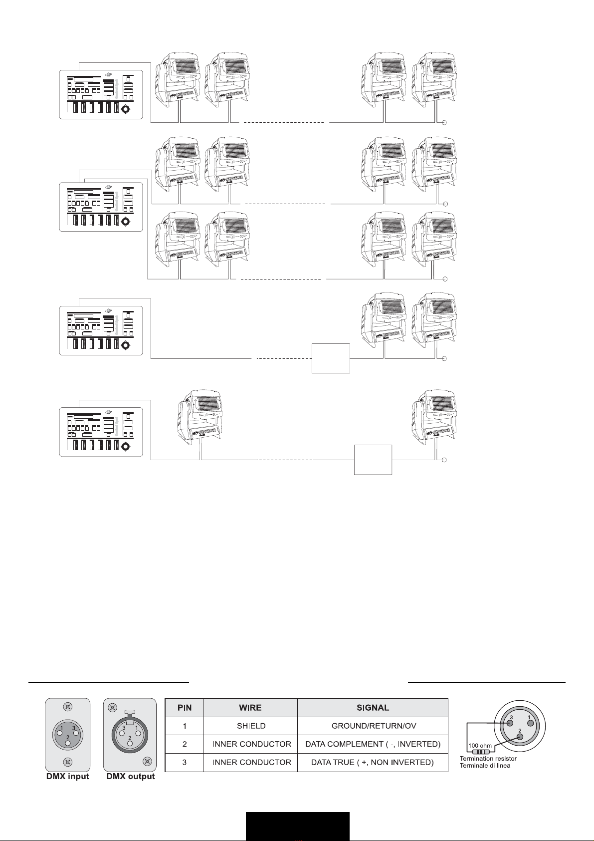
EXAMPLE 1/ESEMPIO 1
EXAMPLE 2/ESEMPIO 2
EXAMPLE 3/ESEMPIO 3
Connection controller-spot to
1DMX 512 OUTPUTover 150mts long
Collegamento centralina-spot ad una sola
LINEA DIUSCITA DMX 512 lunga oltre 150mt.
EXAMPLE 4/ESEMPIO 4
Connection controller-spot to
1DMX 512 OUTPUTover 150mts long
Collegamento centralina-spot ad una sola
LINEA DIUSCITA DMX 512 lunga oltre 150mt.
LASTSPOT/
ULTIMOSPOT
LINE > 150mts (with microphonic or audio cable)
LINEA > 150mt (con cavo microfonico o audio)
SIGNAL AMPLIFIER
AMPLIFICATORE
DISEGNALE
LINE > 150mts (with microphonic or audio cable)
LINEA > 150mt (con cavo microfonico o audio)
SPOTSPOTSPOT
EXAMPLE OF CONNECTION DMX CONTROLLER-SPOT / ESEMPIO DI COLLEGAMENTO CENTRALINA - FARI
DMX CONTROLLER
CENTRALINA DMX
TERMINATION RESISTOR
TERMINALE DILINEA
DMX CONNECTION / COLLEGAMENTO DMX
LASTSPOT/
ULTIMOSPOT
SPOT
SPOT
SPOT
LASTSPOT/
ULTIMOSPOT
SPOTSPOTSPOT
LASTSPOT/
ULTIMOSPOT
SPOT
LASTSPOT/
ULTIMOSPOT
SPOT
DMX CONTROLLER
CENTRALINA DMX
TERMINATION RESISTOR
TERMINALE DILINEA
TERMINATION RESISTOR
TERMINALE DILINEA
DMX CONTROLLER
CENTRALINA DMX
TERMINATION RESISTOR
TERMINALE DILINEA
DMX CONTROLLER
CENTRALINA DMX
SIGNAL AMPLIFIER
AMPLIFICATORE
DISEGNALE
TERMINATION RESISTOR
TERMINALE DILINEA
DMX TERMINAL LINE
The wrong connection of the terminal line or its non-connection are probably the most frequent reasons for the defective functioning
of the DMX line. The terminator is a terminal resistor fitted at the end of the cable furthest from the transmitter.
The terminal resistor should have the same value as the impedance of the connection cable.
We suggest to use a terminal with a 100 ohm resistor.
It is recommanded that all DMX 512 systems have the terminal resistor fitted in the DMX output of the last fixture.
TERMINALE LINEA DMX
L’incorretto o il mancato collegamento del terminale di linea è probabilmente la più comune causa del difettoso funzionamento della
linea DMX. Il terminale di linea DMX consiste in una resistenza posta alla fine della linea.
La resistenza terminale dovrebbe avere idealmente lo stesso valore dell’impedenza del cavo di collegamento.
Noi forniamo un terminale con una resistenza da 100 ohm.
E’ raccomandato per tutti i sistemi DMX 512 inserire il teminale di linea nel connettore uscita DMX dell’ultimo apparecchio
collegato.
Control Spot
StudioDue
StudioDue
R
CHANNEL8/
10
CHANNEL7/
9
CHANNEL4CHANNEL3CHANNEL2CHANNEL1
STANDBY
PROGRAM
FADING
AUTO
MUSIC
MANUALSTEPS
STEPTIME FADING
789
456
123
0
SPOT MORE ALL NONE
TILTPANCOPYCLEARCOPYDELETEINSERT
SELECT SPOTS SPOTS SPOTS
INVERTINVERTPROGRAMPROGRAMSTEPSTEPSTEP
ENTEREXIT
PROGRAMMING
SPOTSFUNCTIONS
PROGRAMSSPOTS STEPS
SELECT
PLAY
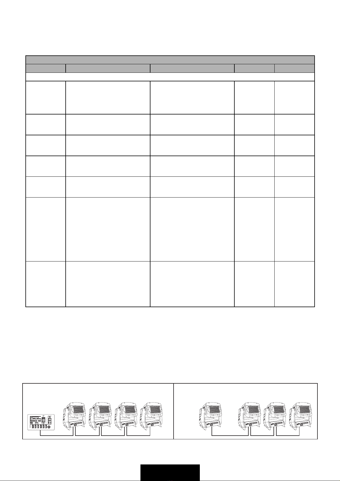
DMX controller
NORMAL MASTER / SLAVE
Spot-1 Spot-1
Set-up = MASTER Set-up = SLAVE Set-up = SLAVE Set-up = SLAVE
Spot-2 Spot-3 Spot-4
Address
set-up 7ch = C001
set-up 6ch = C001
Address
set-up 7ch = C008
set-up 6ch = C007
Address
set-up 7ch = C015
set-up 6ch = C013
Address
set-up 7ch = C022
set-up 6ch = C019
Spot-2 Spot-3 Spot-4
... 8 ...
DMX LISTING - LISTA VALORI DMX
CHANNEL FUNCTION DESCRIPTION DECIMAL PERCENT
1 MOTOR SPEED SPEED MOVEMENT
Slow
Mid1
Mid2
Fast
0..63
64..127
128..191
192..255
0%..24%
25%..50%
51%..74%
75%..100%
2 CYAN CONTINUOUSLY VARIABLE
White
Full color
0
255
0%
100%
3 YELLOW CONTINUOUSLY VARIABLE
White
Full color
0
255
0%
100%
4 MAGENTA CONTINUOUSLY VARIABLE
White
Full color
0
255
0%
100%
5 DIMMER CONTINUOUSLY VARIABLE
0%
100%
0
255
0%
100%
6 BASIC COLORS/RAINBOW Color mixing
Cyan
Yellow
Magenta
Blue
Red
Green
Color mix sequence (slow)
Color mix sequence (mid)
Color mix sequence (fast)
0..25
26..51
52..77
78..103
104..129
130..155
156..181
182..207
208..233
234..255
0%..10%
10%..20%
20%..30%
30%..40%
40%..50%
50%..60%
60%..70%
70%..80%
80%..90%
90%..100%
7 REMOTE RESET/LAMP OFF Normal
Stand-By
Normal
Reset
Normal
Lamp off
Normal
0..31
32..63
64..127
128..191
192..239
240..250
251..255
0%..20%
20%..35%
35%..50%
50%..60%
60%..90%
90%..98%
98%..100%
... 9 ...
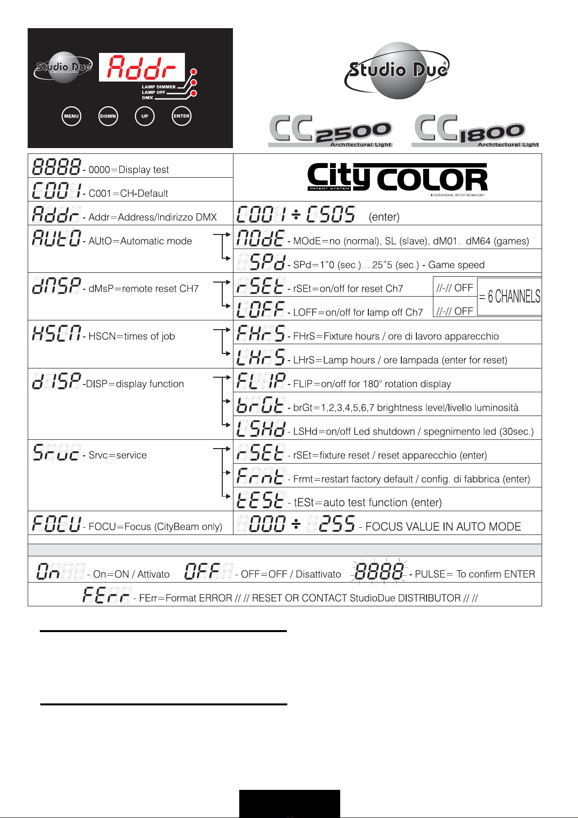
When the fixture is switched on all the motors and the displays start a reset and then position themselves in the deafult
settings: now you can start the set-up of the fixture through the electronic panel with 4“MENU-DOWN-UP-ENTER” keys,
then choose the best setting fololwing the schematics given above.
IMPORTANT. The display will flash after each modification: press ENTER to confirm the change you have chosen
All'accensione dell'apparecchio tutti i motori ed i diplay faranno un ciclo di reset per poi posizionarsi nella configurazione
di default, a questo punto si potrà effettuare il set-up dell'apparecchio a mezzo del pannello elettronico provvisto di 4tasti
"MENU'-DOWN-UP-ENTER, quindi scegliere la migliore configurazione seguendo lo schema sopra riportato.
IMPORTANTE dopo ogni modifica il display lampeggerà, per confermare il cambiamento richiesto sarà necessario premere
ENTER.
eng
ita

... 10 ...
FUNCTIONS FUNCTIONS
PROGRAM PROGRAM
01
dM dM
33
All colour + black/-out (fast)
02 34
All colour (fast)
03 35
All colour (mid)
04 36
All colour (slow)
05 37
All colour (very slow)
06 38
Cyan - green - red (fast)
Cyan - green - red (mid)
Cyan - green - red (slow)
Cyan - green - red (very slow)
Green-yellow-red (fast)
Green-yellow-red (mid)
Green-yellow-red (slow)
Green-yellow-red (very slow)
Yellow-cyan-magenta (fast)
Cyan-green-red-yellow-white-magenta (fast)
White-cyan (fast)
White-magenta (fast)
White-green (fast)
White-red (fast)
White-red (slow)
Yellow-green (fast)
Cyan-magenta (fast)
Cyan-yellow (fast)
Magenta-yellow (fast)
Yellow-green (slow)
Cyan-magenta (slow)
Cyan-yellow (slow)
Magenta-yellow (slow)
White-cyan (mid)
White-magenta (mid)
White-green (mid)
White-red (mid)
White-red (very slow)
Yellow-green (mid)
Cyan-magenta (mid)
Cyan-yellow (mid)
Magenta-yellow (mid)
Yellow-green (very slow)
Cyan-magenta (very slow)
Cyan-yellow (very slow)
Magenta-yellow (very slow)
WHITE (FIX)
YELLOW (FIX)
MAGENTA (FIX)
RED (FIX)
GREEN (FIX)
WOOD (FIX)
CYAN (FIX)
LIGHT YELLOW (FIX)
LIGHT CYAN (FIX)
LIGHT MAGENTA (FIX)
LIGHT RED (FIX)
LIGHT GREEN (FIX)
LIGHT WOOD (FIX)
ORANGE (FIX)
White-cyan (slow)
White-magenta (slow)
White-green (slow)
White-cyan (very slow)
White-magenta (very slow)
White-green (very slow)
Yellow-cyan-magenta (mid)
Yellow-cyan-magenta (slow)
Yellow-cyan-magenta (very slow)
07 39
08 40
09 41
10 42
11 43
12 44
13 45
14 46
15 47
16 48
17 49
18 50
19 51
20 52
21 53
22 54
23 55
24 56
25 57
26 58
27 59
28 60
29 61
30 62
31 63
32 64
LIST OF THE AVAILABLE GAMES / ELENCO DEI GIOCHI DISPONIBILI
This manual suits for next models
4
Table of contents
Other STUDIODUE Projector manuals


