Bacharach MultiZone User manual

Instruction 3015-5506 1
Scope
These instructions describe how to replace the IR bench in the Halogen Gas Monitor (Single-Zone or Multi-
Zone), Ammonia Gas Monitor (SZ or MZ), and the Carbon Monoxide Gas Monitor Single Zone.
It is assumed that the user is familiar with the operation of the appropriate monitor. If necessary, refer to the
instructions for detailed operation and maintenance information. Table 1 provides a list of the appropriate
instructions and parts necessary for each model.
* Not for individual sale. Used for ID purposes only. (i.e. To order replacement kit for your bench which is
labeled model number 3015-5087, place order for kit number 3015-5509.)
Table 1: Part Number Information
Items Required:
Replacement IR Optical Bench Kit (includes bench assembly, cable ties, and instruction sheet)
Cable Ties (Qty. 2) 3015-2835
Instruction Sheet 3015-5506
Medium Phillips Head Screwdriver
Small Flat-Blade Screwdriver
Wire Cutter (for removing cable ties)
Removing the IR Bench
1. Find the AC power source for the monitor and switch OFF the AC circuit breaker. Ensure that the
monitor’s front panel green MONITOR ON indicator is OFF.
2. Use a Phillips screwdriver to remove the monitor’s two door screws, and then open the door.
3. Take time to familiarize yourself with the internal components displayed on the following page. Figure 1
is a diagram of the Single Zone monitors while Figure 2 is a diagram of the Multi-Zone monitors. Figure
3 shows the R37 component used to adjust the IR emitter drive level. This is only present on older
models.
Monitor Type Bench Replacement Kit Solo Bench* Instruction Manual
HGM-SZ 3015-4572 3015-5086 3015-4256
HGM-MZ 3015-4572 3015-5086 3015-5074
AGM-SZ 3015-4492 3015-5087 3015-4256
AGM-MZ 3015-4492 3015-5087 3015-5074
CO2-SZ 3015-5507 3015-5090 3015-4603
CO2-MZ 3015-5507 3015-5090 3015-5074
Single Zone / Multi-Zone Bench
Replacement
Instruction 3015-5506
Rev. 0 – August 2010

Instruction 3015-5506
2
Figure 3: R37 Component
Figure 1: Single Zone Components
Gas inlet
Gas
Outlet
DET
Connector
J6
IR Source
Connecto
r
J5
10-PIN Connector
(Detector)
12-PIN
Connector
(IR Source)
IR Bench IR Set R37
(older version PC’s)
Figure 2: Multi-Zone Components
Gas inlet
Gas
Outlet
IR Source
Connector J5
10-PIN Connector
(Detector)
IR Bench
DET
Connector
J6
12-PIN
Connector
(IR Source)
IR Set R37
(older version PC’s)

Instruction 3015-5506 3
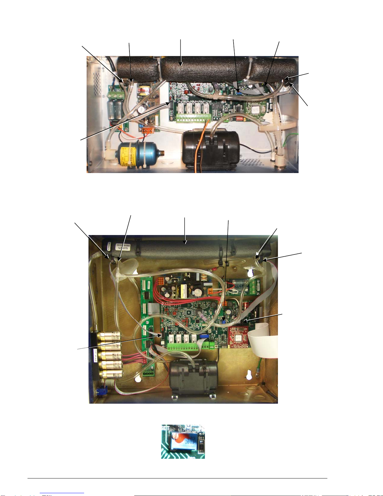
4. To remove the old IR bench:
a. Pull the 10-pin and 12-pin electrical connectors from their respective sockets on the IR bench.
Note that these connectors may have been secured with either hot glue or cable ties for
shipping purposes. As necessary, carefully remove anything securing the connector then
remove the connector.
b. Pull the tubing from the gas-inlet and outlet fittings on the IR bench.
c. Using wire cutters, cut the two cable ties that secure the IR bench to the enclosure, then
remove the bench from the monitor.
Installing the New IR Bench
5. Perform the following to install the new IR bench:
a. Remove protective caps from the gas-inlet and gas-outlet fittings on the new IR bench.
b. Position the new bench inside the enclosure so that the end with the 12-pin electrical connector (IR
Source) is located on the right and that the gas fittings are facing towards the monitor’s main board.
c. Using the two cable ties supplied in the kit, secure the bench to the cable-tie mounts on the side wall
of the enclosure. Cut off any cable-tie excess.
d. Connect tubing from pump to the IR bench gas-outlet fitting, and connect tubing from purge valve V1
to the IR bench gas-inlet fitting.
e. Plug the 12-conductor ribbon cable from IR SOURCE connector J5 on the main board into the 12-pin
IR bench connector.
f. Plug the 10-conductor ribbon cable from DET connector J6 on the main board into the 10-pin IR bench
connector.
6. Check to ensure that the new IR bench is properly secured, and that all tubing and electrical connectors
are tight.
7. Turn ON the monitor’s AC circuit breaker.
Single Zone Monitors
This section describes how to proceed if installing a new IR bench in a Single Zone Monitor.
Adjusting IR Bench Emitter Drive Power Level
1. To adjust the IR emitter power level:
a. With the monitor in its MEASURE (normal) mode, enter the main menu and use the keypad buttons to
place the arrow (>) on the display next “CAL.”
b. Press the Right-Arrow and ENTER buttons at the same time to display the revision screen.
c. Press “QUIT” to display the setup screen.
d. Place the arrow (>) next to the “IR” and press “ENTER.”
e. Change the IR emitter drive level to 450 mW by using the UP/DOWN arrow keys (newer models). If
present, change the drive level to 450 mW by adjusting R37 (located on main PCB board) clockwise
(older models).
f. Press “SILENCE/QUIT” to return to the setup screen.

Instruction 3015-5506
4
Adjusting the IR Bench Voltage
1. To adjust the IR bench voltage:
a. With the monitor in its MEASURE (normal) mode, enter the main menu and
use the keypad buttons to place the arrow (>) on the display next “CAL.”
b. Press the Right-Arrow and ENTER buttons at the same time to display the
revision screen.
c. Press “QUIT” to display the setup screen.
d. Place the arrow (>) next to the “DIGIPOT” and press “ENTER.”
2. Observe the IR VOLT reading. Use the Up/Down arrow buttons to obtain a
reading of 4.200 ±0.100 volts. Note that the DIGIPOT value is not important
as long as the voltage is 4.200 ±0.100 volts.
IMPORTANT! If adjusting the DIGIPOT does not reach 4.200 ±0.100 volts, return to Step 1 of the
previous section to lower the IR emitter setting. If the IR emitter setting is 450 ±20 mW,
adjust the new IR emitter setting to 375 ±20 mW. Repeat the DIGIPOT procedure with
the new IR emitter setting.
3. Press “ENTER” to save this setting and then press “QUIT” twice (2x’s) to exit the monitor’s setup
mode.
4. A purge cycle will be performed upon exiting the setup mode and then the monitor will automatically
return to its MEASURE mode. If there are no faults the new IR bench has been successfully installed.
5. Close and secure the enclosure door using the screws removed in Step 2.
6. The monitor can now be placed back into service.
Multi-Zone Monitors
This section describes how to proceed if installing a new IR bench in a Multi-Zone monitor.
Adjusting IR Bench Emitter Drive Power Level
1. To adjust the IR emitter power level:
a. With the monitor in its MEASURE mode, enter the main system setup menu.
b. Enter Service Mode by highlighting “Service Mode” and pressing “ENTER” twice (2x’s).
c. Navigate to “SYSTEM” and press “ENTER” to enter the system setup screen (while in Service Mode).
d. Navigate to “More” in the bottom-right corner and press “ENTER.”
e. Navigate to “IR DIGIPOT” in the bottom-right and press “ENTER.”
f. Observe the “MW” reading the in lower-right portion of the screen. Change the IR emitter drive level to
450 mW by using the UP/DOWN arrow keys (newer models). If present, change the drive level to 450
mW by adjusting R37 (located on main PCB board) clockwise (older models). Press “ESC” to return to
the Service Mode setup screen.
>DIGIPOT MODEL
P CAL IR
DIGIPOT = 193
IR VOLT = 4.200
SILENCE ZONETMP
SQUELCH >CAL
REV M D Y
x.xx at HH:MM:SS

Instruction 3015-5506 5
Adjusting the IR Bench Voltage
1. To adjust the IR bench voltage:
a. With the monitor in its MEASURE mode, enter the main system setup menu.
b. Enter Service Mode by highlighting “Service Mode” and pressing “ENTER” twice (2x’s).
c. Navigate to “SYSTEM” and press “ENTER” to enter the system setup screen (while in Service Mode).
d. Navigate to “More” in the bottom-right corner and press “ENTER.” The following screen will be
displayed.
e. Navigate to “DET DIGIPOT” in the top-right and press “ENTER.”
2. Observe the IR VOLT reading. Use the Up/Down arrow buttons to obtain a reading of 4.200 ±0.100
volts. Note that the DIGIPOT value is not important as long as the voltage is 4.200 ±0.100 volts.
IMPORTANT! If adjusting the DIGIPOT does not reach 4.200 ±0.100 volts, return to Step 1 of the
previous section to lower the IR emitter setting. If the IR emitter setting is 450 ±20 mW,
adjust the new IR emitter setting to 375 ±20 mW. Repeat the DIGIPOT procedure with
the new IR emitter setting.
3. Press “ENTER” to save this setting and then press “ESC” once (1x) to exit the monitor’s setup mode.
4. Navigate to “IN SERVICE” and press “ENTER” twice (2x’s) to exit Service Mode. Press “ESC” to
return to the main measuring screen.
5. A pressure check and purge cycle will be performed upon exiting Service Mode and then the monitor
will automatically return to its MEASURE mode. If there are no faults the new IR bench has been
successfully installed.
6. Close and secure the enclosure door using the screws removed in Step 2.
7. The monitor can now be placed back into service.
DIGIPOT= 180
IR VOLT= 4.21
V= 4.7 MA= 96
R= 49 MW= 450

Instruction 3015-5506
6
Headquarters:
621 Hunt Valley Circle, New Kensington, PA 15068-7074
Toll Free: 1-800-736-4666 • Tel: +1-724-334-5000 • Fax: +1-724-334-5001
Printed in U.S.A. ® Registered Trademark of Bacharach Inc.
Other manuals for MultiZone
1
This manual suits for next models
1
Table of contents
Popular Accessories manuals by other brands

Polar Electro
Polar Electro Y6 user manual

SCHOTT
SCHOTT Solar Photovoltaic Modules Installation and user manual

Verano
Verano V124 - CALPE Measuring instruction

Space Energy
Space Energy M37 user manual

ROSE DISPLAYS
ROSE DISPLAYS ANOGOTCHA PLUS WITH MULTICLIPS manual

Siemens
Siemens QBM Series installation instructions