Bader KR-454 User manual

Digital air- conditioner controller KR- 454
OPERATING INSTRUCTIONS
NEOPLAN
AIR- CONDITIONER- CONTROLLER
KR-454
October 1998
Version 1.14
INDUSTRIE-ELEKTRONIK
Control and regulating systems for vehicle air conditioning
D-71691 Freiberg a.N., Siemensstr.21
Phone: +49 7141 / 68877 - 0 Fax: +49 7141 / 68877 - 39
page: 1
of: 42
04541530.SDW
Issue: October 1998 - Copyright (C) BADER GmbH - Alterations reserve

Digital air- conditioner controller KR- 454
CAUTION!
IMPORTANT SAFETY TIPS:
As a leader of a vehicle you must dedicate full attention to the traffic.
Always operate with your controller in a way that you are equal
to the current traffic situation.
In critical situations we advise against operating.
Please consider that already at a rate of 50 k.p.h the vehicle will go
about a distance of 14 m / sec.
In the event of occurrence of a trouble please look for the next car park
and try to overcome the error with the use of the manual.
IMPORTANT INFORMATION FOR THE USER:
Unplug the air-conditioner centre before carrying out welding work on
the vehicle.
Errors and faults which have not actually occurred in the vehicle may be
indicated if you attempt to start the engine with a partially discharged
vehicle battery.
All internal memories of the computer are reset by briefly interrupting the
air-conditioner centre's power supply (wait approx. 30 sec.) or by
pressing the "RESET" keys.
(Then please wait for the air-conditioner centre to conduct its self-test
approx. 3 min.)
Always keep the air-conditioner controller dry!
Please clean the surface of the control panel only with a damp cloth!
INDUSTRIE-ELEKTRONIK
Control and regulating systems for vehicle air conditioning
D-71691 Freiberg a.N., Siemensstr.21
Phone: +49 7141 / 68877 - 0 Fax: +49 7141 / 68877 - 39
page: 2
of: 42
04541530.SDW
Issue: October 1998 - Copyright (C) BADER GmbH - Alterations reserve

Digital air- conditioner controller KR- 454
CONTENTS: PAGE
1.....KEY ASSIGNMENT ON THE FRONT PANEL 4
Key assignment air-cond. controller passenger compartment 5
.......LED-Display 5
2.....QUICK-START OPERATING INSTRUCTIONS 6
3.....DESCRIPTION OF KEY FUNCTION 7
3.1. .Operation driver's cockpit (front box) 7
3.2..Operation of air-cond. controller passenger compartment 9
3.3..Setting the time 12
3.4..Programming the auxiliary heating system 13
4.....FAULTS AND ERRORS - DIAGNOSIS 14
4.1..Error memory function 15
4.2..Calling and clearing the contents of the error memory 15
4.3..List of error messages - double-decker coach 16
5.....SPECIAL FUNCTIONS 18
5.1. .Intensity control of the LED-display 18
5.2..Max. -/Min.-setting of the setpoint controls pass. compartment
.......temperature (Override-mode) 19
5.3. .Minimum speed setting of the roof duct fans 19
5.4. .Reset of the internal memory 20
5.5..Deactivating the auto start function (Automatic-mode) 20
5.6..Encoding with vehicles without air-conditioning 21
5.7..Special functions of the display - roof duct temperature 21
6.....ACCESSORY UNITS 22
6.1..Emergency ventilation switch and RS-232 interface 22
7.....SYSTEM-SELF-TEST 23
7.1..The test programs in detail 24
8.....CONNECTING DIAGRAM KR- 454 29
8.1. .Emergency switch module 30
9.....SERVICE INFORMATION KR- 454 32
10...BLOCK SCHEMA OF CONTROL 33
11.. .TECHNICAL DATA 34
12.. .LIST OF ERRORS WITH REMEDIAL MEASURES 35
INDUSTRIE-ELEKTRONIK
Control and regulating systems for vehicle air conditioning
D-71691 Freiberg a.N., Siemensstr.21
Phone: +49 7141 / 68877 - 0 Fax: +49 7141 / 68877 - 39
page: 3
of: 42
04541530.SDW
Issue: October 1998 - Copyright (C) BADER GmbH - Alterations reserve

Digital air- conditioner controller KR- 454
1. KEY ASSIGNMENT ON THE FRONT PANEL
Key assignment, temperature, driver's cockpit (Front box)
Key S1: Front box fan, stage I
Key S2: Front box fan, stage II
Key S3: Flap, fresh air/circulating air
Key S4: Flap, screen + screen defrost
Key S5: Flap, driver's cockpit/centre aisle
Keys S4+S5: Lamp test with ignition switched off
Key S15: Setpoint key (-) for valve position at the driver's cockpit (front box)
Key S16: Setpoint key (+) for valve position at the driver's cockpit (front box).
INDUSTRIE-ELEKTRONIK
Control and regulating systems for vehicle air conditioning
D-71691 Freiberg a.N., Siemensstr.21
Phone: +49 7141 / 68877 - 0 Fax: +49 7141 / 68877 - 39
page: 4
of: 42
04541530.SDW
Issue: October 1998 - Copyright (C) BADER GmbH - Alterations reserve

Digital air- conditioner controller KR- 454
Key assignment, air-conditioner control system, passenger compartment
Key S6: -Automatic mode with ignition switched on
-Diagnostic mode with ignition switched off with S9
Key S7: -Ventilation mode, stage I
Key S8: -Ventilation mode, stage II
Key S9: -Flap, fresh air/circulating air with ignition switched on with S6
Key S10: -Auxiliary heating system
Key S11: -Convectors on/off
Key S12: -Setting time or time switch (h) with "ignition off"
-Increment test mode
-LED-display reduce intensity on/off
Key S13: -Setting time or time switch (min) with "ignition off"
-Decrement test mode
-Passenger compartment temperature with “igniton on“
Key S14: -Activating time setting mode and time switch for auxiliary heating
system with "ignition off"
-Confirm key for new time entered
-Outside temperature display
Key S17: -Setpoint key ( - ) for passenger compartment temperature upper deck
Key S18: -Setpoint key ( + ) for passenger compartment temperature upper deck
Key S19: -Setpoint key ( - ) for passenger compartment temperature lower deck
Key S20: -Setpoint key ( + ) for passenger compartment temperature lower deck
LED DISPLAY
The following information is shown on the LED display:
1) With the ignition switched off: -Setting the time and time switch for the
auxiliary heating system
-Diagnosis
-Dot display (blinks as tell-tale indicator for
processor function)
2) With ignition switched on: -Passenger compartment and outside
temperature display with
-Frost warning
-Time
-Error message
-Front box opening or setpoint passenger
compartment temperature
INDUSTRIE-ELEKTRONIK
Control and regulating systems for vehicle air conditioning
D-71691 Freiberg a.N., Siemensstr.21
Phone: +49 7141 / 68877 - 0 Fax: +49 7141 / 68877 - 39
page: 5
of: 42
04541530.SDW
Issue: October 1998 - Copyright (C) BADER GmbH - Alterations reserve

Digital air- conditioner controller KR- 454
2. QUICK-START OPERATING INSTRUCTIONS
These instructions provide you with general information on the individual functions of
the KR-454 air-conditioner controller.
DISPLAY
The outside temperature is always displayed as the basic display with the ignition
switched on.
If the ignition is switched off, the decimal point between the minutes and hours
display blinks as a tell-tale indication of the function of the microprocessor. The
display is used to show the data for error detection in test mode.
AUTO
The normal mode of operation of the air-conditioner controller is Automatic mode.
This mode is activated automatically with the engine running. Both the LED-display
“Auto“ (S6) and the “Convector“ (S11) are flashing. You can now set the required
passenger compartment temperature for the passenger compartment with the
setpoint keys S17 or S18. You can set a temperature between 18°and 28°C.
VENTILATION
The roof duct fans can be switched on manually with keys S7 and S8. This closes the
motor valves for the roof duct heaters and ventilates at 40 % or 100 % of the fan
capacity.You can fix the fan speed to 40% or 100% by pressing keys S7 or S8 in
Automatic mode. (Caution: The automatic passenger compartment control is
obstructed by that.)
CONVECTORS
The convectors are switched on automatically and control their temperature as preset
on the setpoint passenger compartment in Automatic mode. The value sensed by the
convector sensor serves as the actual value, and the passenger compartment
temperature sensor limits heating of the passenger compartment.
The convectors can also be switched on during Ventilation- and Stationery heating
mode and are controlled as in Automatic mode.
FRONT BOX
The air-conditioner controller includes a front box control system for the driver's
cockpit accommodated in the left-hand part of the unit. You enter the temperature
with the setpoint keys S15 or S16. Various keys permit you to operate the flaps and
the 2-stage fan.
3. DESCRIPTION OF KEY FUNCTIONS
INDUSTRIE-ELEKTRONIK
Control and regulating systems for vehicle air conditioning
D-71691 Freiberg a.N., Siemensstr.21
Phone: +49 7141 / 68877 - 0 Fax: +49 7141 / 68877 - 39
page: 6
of: 42
04541530.SDW
Issue: October 1998 - Copyright (C) BADER GmbH - Alterations reserve

Digital air- conditioner controller KR- 454
3.1. OPERATION, DRIVER'S COCKPIT (FRONT BOX)
S15 S16 Setting the setpoint for the temperature of the driver's cockpit
Setting- and display range 0-100% in 1%-steps with the standard
model without air-conditioning. With air-conditioned front box with
incorporated temperature sensor the display of the setting range
has got a decimal dot. Display range from F 0.0 to F10.0.
The actual setpoint of the driver's cockpit is displayed by a short
pressing (press and release) of keys S15 or S16.
Display f.ex.“F50“ or “F5.0“.
You can change the setpoint in 1%-steps per key pressure with
keys S15 and S16.If you press any key for more than 2 seconds
the setpoint is changed at a high speed.
If you don't press any of these keys the actual setpoint is stored
and displayed. The display goes back to its former status after 5
seconds.
S1: Front box fan 40%
Also functions without the engine running
S2: Front box fan 100%
Functions only when the engine is running
S3: Flap “Fresh air/circulating air“, driver's cockpit
Basic setting: Fresh air
S4 Flap “Screen defrost“
Basic setting: flap open
INDUSTRIE-ELEKTRONIK
Control and regulating systems for vehicle air conditioning
D-71691 Freiberg a.N., Siemensstr.21
Phone: +49 7141 / 68877 - 0 Fax: +49 7141 / 68877 - 39
page: 7
of: 42
04541530.SDW
Issue: October 1998 - Copyright (C) BADER GmbH - Alterations reserve

Digital air- conditioner controller KR- 454
The flap is opened or closed if you press the key shorter than 2
seconds. The key - LED S4 flashes with open flap.
The defrost function is initiated if you press the key longer than 2
seconds. That means:
- Flap screen opens, key - LED S4 blinks
- Flap centre aisle closes, key - LED S5 goes out
- Flap circulating air closes (fresh air), key- LED S3 goes out
- Front box fan 100%, key - LED S2 flashes
- Front box valve opens, LED - display f.ex. “F100“ for 5 sec.
You can reset the defrost function by pressing alternatively keys
S1 , S2 , S3 , S4 , S5 , S15 or S16 .
S5 Flap “Driver's cockpit/centre aisle“
The flap opens when you press the key. In this setting a part of the
air stream is directed towards the driver and into the centre aisle.
NOTES:
3.2 OPERATION OF AIR-CONDITIONER CONTROL SYSTEM,
PASSENGER COMPARTMENT
INDUSTRIE-ELEKTRONIK
Control and regulating systems for vehicle air conditioning
D-71691 Freiberg a.N., Siemensstr.21
Phone: +49 7141 / 68877 - 0 Fax: +49 7141 / 68877 - 39
page: 8
of: 42
04541530.SDW
Issue: October 1998 - Copyright (C) BADER GmbH - Alterations reserve

Digital air- conditioner controller KR- 454
S17 S18 Setting the setpoint for temperature upper deck
Setting- and display range from 18°-28° C
The actual setpoint of the upper deck is displayed by a short
pressing (press and release) of keys S17 or S18.
Display => f.ex. “ 20 “
You can change the setpoint with keys S17 and S18 in 1°C -steps
per key pressure.
The actual setpoint is displayed after releasing the corresponding
key.
If you don't press the keys for further 5 sec. the value is stored and
the display goes back to its former status.
S19 S20 Setting the setpoint for temperature lower deck
Setting- and display range from 18°-28° C
The actual setpoint of the lower deck is displayed by a short
pressing (press and release) of keys S19 or S20.
Display => f.ex. “ 20 “
You can change the setpoint with keys S19 and S20 in 1°C -steps
per key pressure.
The actual setpoint is displayed after releasing the corresponding
key.
If you don't press the keys for further 5 sec. the value is stored and
the display goes back to its former status.
S6 AUTOMATIC MODE
The temperature control system of the passenger compartment is
switched on automatically after starting the engine. The LED of
key S6 flashes. You can switch off the Automatic mode by
pressing key S6. Automatic control is only possible with the engine
INDUSTRIE-ELEKTRONIK
Control and regulating systems for vehicle air conditioning
D-71691 Freiberg a.N., Siemensstr.21
Phone: +49 7141 / 68877 - 0 Fax: +49 7141 / 68877 - 39
page: 9
of: 42
04541530.SDW
Issue: October 1998 - Copyright (C) BADER GmbH - Alterations reserve

Digital air- conditioner controller KR- 454
running. The fan and the air- conditioner are always switched off
when you switch off the ignition. The motor valves and flaps
remain in position. In Automatic mode the passenger compartment
temperature is automatically regulated to the temperatures set
with the setpoint keys using the components of the system (fan,
air-conditioner, heater).
As a special function, you can switch off automatic speed control
of the roof duct fans with the ventilation keys (S7/S8). The fan
speed is then permanently set to 40 % (stage I - S7) or 100 %
(stage II - S8) as is the case in Ventilation mode (f.ex. to vent
the vehicle quickly).
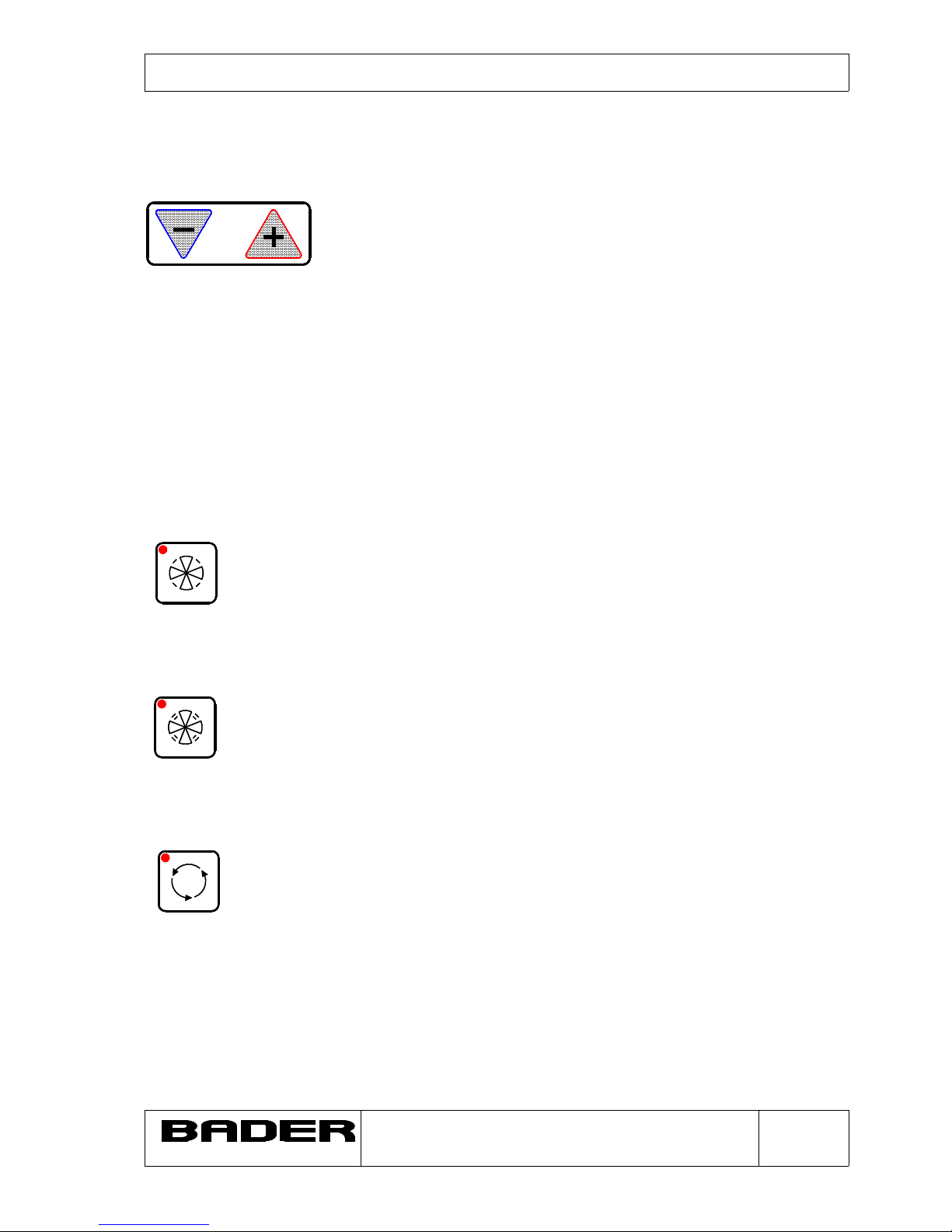
S7 VENTILATION MODE, stage I
When you press key S7, the motor valves of the roof duct heater
close and the roof duct fans are switched on to stage I (approx. 40
%). This ventilation mode is possible even without the engine
running and only with the ignition switched on. The incorporated
undervoltage protection facility in the unit avoids exhaustive
discharge of the vehicle battery.
S8 VENTILATION MODE, stage II
Function as with key S7, but ventilation capacity 100 %.
This key operates only with the engine running (alternator).
NOTE: The fans are increased slowly and in controlled manner to
100% fan capacity in order to avoid a high making current! (this
takes approx. 15 sec.!)
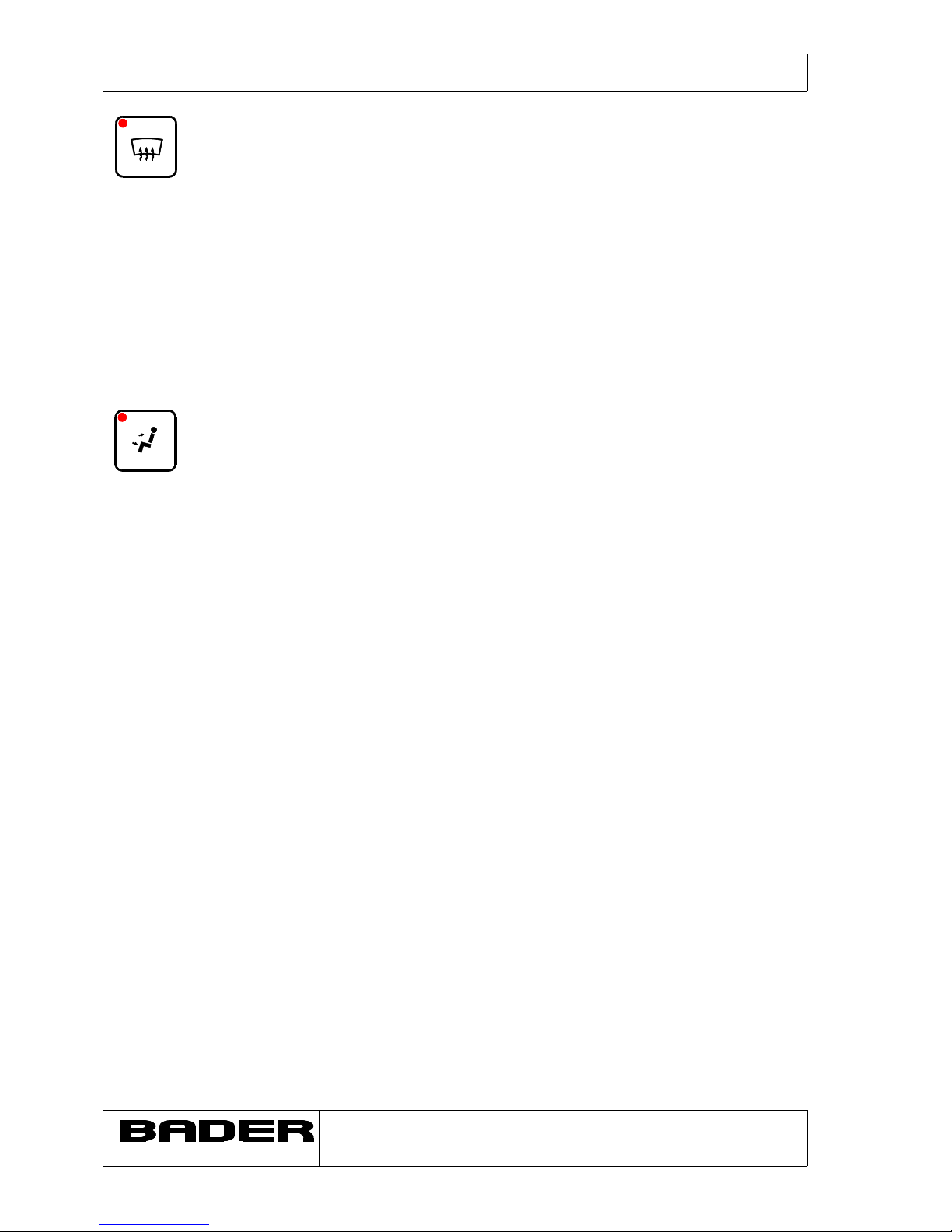
S9 Flap "Fresh air/circulating air" passenger compartment
You can use this key when on the move to switch the ventilation
system to circulating air, and an automatic function switches back
to fresh air after 10 min.
In addition, the system switches over automatically to circulating
air at temperatures above 28°C and below -20°C (according to
the function chart).
S10 AUXILIARY HEATING SYSTEM
The auxiliary heating system is started up when you press this
key. Operation of the auxiliary heating system is indicated by the
LED in the key.
INDUSTRIE-ELEKTRONIK
Control and regulating systems for vehicle air conditioning
D-71691 Freiberg a.N., Siemensstr.21
Phone: +49 7141 / 68877 - 0 Fax: +49 7141 / 68877 - 39
page: 10
of: 42
04541530.SDW
Issue: October 1998 - Copyright (C) BADER GmbH - Alterations reserve

Digital air- conditioner controller KR- 454
S11 CONVECTORS
This key can be used to switch the convectors on and off. They
are also controlled via their own sensor in Ventilation mode,
dependent on the set temperature (setpoint keys S17, S18, S19,
S20). The measured passenger compartment temperature is used
as the basis for limiting the temperature for convector control.
S12 PASSENGER COMPARTMENT TEMPERATURE UPPER DECK
AND SETTING THE TIME
When setting the time and the time switch, this key is used to
increment (count up) the hours display. In Diagnostic mode,
this key is used to increment the diagnostic steps.
S13 PASSENGER COMPARTMENT TEMPERATURE LOWER DECK
AND SETTING THE TIME
When setting the time and the time switch, this key is used to
increment (count up) the minute display. In Diagnostic mode, this
key is used to decrement (count down) the diagnostic steps.
S14 OUTSIDE TEMPERATURE
With ignition switched on:
-The outside temperature is displayed.
-The current time is displayed after you press the function key.
With ignition switched off:
-Activating Clock-set mode
-Confirm key for new time entered.
3.3 SETTING THE TIME
S14 OUTSIDE TEMPERATURE/TIME
INDUSTRIE-ELEKTRONIK
Control and regulating systems for vehicle air conditioning
D-71691 Freiberg a.N., Siemensstr.21
Phone: +49 7141 / 68877 - 0 Fax: +49 7141 / 68877 - 39
page: 11
of: 42
04541530.SDW
Issue: October 1998 - Copyright (C) BADER GmbH - Alterations reserve

Digital air- conditioner controller KR- 454
PRECONDITION: Engine off, ignition off!
You can call Clock-set mode with key S14. Keys S12 and
S13 light. The current system time is displayed on the
display. If you do not press any other key, the display
disappears after approx. 5 seconds and the previously set
system time is retained.
After you press key S14, you can then press key S12
S12
to increment the hours display. If you keep the key
pressed, the display counts up in 1/2 second steps.
You can set the minute display with key S13
S13
and the same operating steps apply as for key
S12.
After you set the hours and minutes display, you can confirm the
new time entered with key S14. If you do not confirm within
appprox. 5 seconds, the unit retains the previously set system
time.
3.4 PROGRAMMING THE AUXILIARY HEATING SYSTEM
S14 The same operating steps as for setting the time apply to
programming the time switch for the auxiliary heating system.
INDUSTRIE-ELEKTRONIK
Control and regulating systems for vehicle air conditioning
D-71691 Freiberg a.N., Siemensstr.21
Phone: +49 7141 / 68877 - 0 Fax: +49 7141 / 68877 - 39
page: 12
of: 42
04541530.SDW
Issue: October 1998 - Copyright (C) BADER GmbH - Alterations reserve

Digital air- conditioner controller KR- 454
However, after you press key S14 (Setting mode), you must then,
within approx. 5 sec press S10 (AUXILIARY HEATING SYSTEM)
S10
Then, as when setting the time, you must program the required
switch-on time for the auxiliary heating system and confirm this
with key S14 (Key-LED S10 blinks in 2-second-steps).
If the auxiliary heating system has been started automatically, it
can be switched off again with key S10. Otherwise, the heating
system switches off again automatically after 1 hour. The
convectors are also switched on and the temperature is
controlled together with the auxiliary heating system.
The temperature value of the setpoint control is used as is the
case with passenger compartment temperature control. Set the
relevant setpoint to "min" if you do not wish to pre-heat
a deck.
The current switch-on time can be checked with the Automatic
key S6 with the ignition off. If the auxiliary heating system has
been programmed, you will see the switch-on time on the
display.You will see display "OFF" if no times have been
programmed.
This check display is cleared again after approx. 5 seconds.
If you want to reset a programmed switch-on-time call the
starting time as when programming; but don't confirm it with key
S14.
4. FAULTS AND ERRORS - DIAGNOSIS
The KR-454 air-conditioner controller features a sophisticated
error and fault diagnosis program.
INDUSTRIE-ELEKTRONIK
Control and regulating systems for vehicle air conditioning
D-71691 Freiberg a.N., Siemensstr.21
Phone: +49 7141 / 68877 - 0 Fax: +49 7141 / 68877 - 39
page: 13
of: 42
04541530.SDW
Issue: October 1998 - Copyright (C) BADER GmbH - Alterations reserve

Digital air- conditioner controller KR- 454
This error and fault diagnosis program runs, as it were, "in the
background" during normal air-conditioner operation and
monitors the sensors, setpoint potentiometers and valve
potentiometers and the switched outputs of the valve motors and
other loads for discontinuity and short circuit. If one or more
faults or errors occur when on the move, the time display is
cleared and the relevant malfunction is displayed in the form of
a consecutive number. An "E" for ERROR in front of the number
signals the error.
S14
The LED in key S14 blinks simultaneously.
You must then "acknowledge" the fault with this key. The air-
conditioner centre then continues to operate in Emergency mode,
and the sensor values are simulated for instance, dependent
on the operating state. This Emergency mode can be seen from a
dot at the far right on the display. The time is displayed once
again after you acknowledge the error.
If there is a valve potentiometer error, the air-conditioner
controller attempts to operate the valves even without a check-
back signal so as to permit it to regulate the system, even if
not precisely.
If an output has a short circuit, this output is disconnected and
the relevant error is shown on the display. The system attempts
to reactivate the output each time you switch the ignition off and
on.
4.1 ERROR MEMORY FUNCTION
If an error occurs when on the move and if this error is
acknowledged, the error number is stored in the so called unit's
error memory.
INDUSTRIE-ELEKTRONIK
Control and regulating systems for vehicle air conditioning
D-71691 Freiberg a.N., Siemensstr.21
Phone: +49 7141 / 68877 - 0 Fax: +49 7141 / 68877 - 39
page: 14
of: 42
04541530.SDW
Issue: October 1998 - Copyright (C) BADER GmbH - Alterations reserve

Digital air- conditioner controller KR- 454
These errors are displayed again each time you switch on the
ignition in order to indicate the defect to you. The contents of the
error memory must be cleared manually when the error has been
rectified.
4.2 CALLING AND CLEARING THE CONTENTS OF THE ERROR MEMORY
S6 S9 The contents of the error memory can be called by pressing keys
S6 and S9 simultaneously with the ignition switched off.
You will first see the program version of the unit on the display
(e.g. 1.10).
You will then see the number of errors detected, shown by an “A“
and a consecutive number.
S12 S13 You can then “page forwards and backwards in the error memory
with keys S12 and S13.
You can clear the contents of the error memory by pressing
both keys simultaneously.
You will then see "A 00" on the display.
If there is still an error in the system (e.g. sensor discontinuity),
this error message will be displayed again immediately.
4.3 LIST OF ERROR MESSAGES - DOUBLE-DECKER-COACH
Error 1 Working-hour meter not set at 0
Error 3 Short circuit, outside sensor
Error 4 Discontinuity, -"-
Error 5 Short circuit, passenger compartment sensor lower deck
INDUSTRIE-ELEKTRONIK
Control and regulating systems for vehicle air conditioning
D-71691 Freiberg a.N., Siemensstr.21
Phone: +49 7141 / 68877 - 0 Fax: +49 7141 / 68877 - 39
page: 15
of: 42
04541530.SDW
Issue: October 1998 - Copyright (C) BADER GmbH - Alterations reserve

Digital air- conditioner controller KR- 454
Error 6 Discontinuity, -"-
Error 7 Short circuit, roof duct sensor lower deck
Error 8 Discontinuity, -"-
Error 9 Short circuit, convector sensor, front lower deck
Error 10 Discontinuity, -"-
Error 11 Short circuit, convector sensor, rear lower deck
Error 12 Discontinuity, -"-
Error 13 Short circuit, passenger compartment sensor upper deck
Error 14 Discontinuity, -"-
Error 15 Short circuit, roof duct sensor upper deck
Error 16 Discontinuity, -"-
Error 17 Short circuit, convector sensor, front upper deck
Error 18 Discontinuity, -"-
Error 19 Short circuit, convector sensor, rear upper deck
Error 20 Discontinuity, -"-
Error 21 Short circuit front box sensor driver's cockpit (option)
Error 22 Discontinuity -“-
Error 23 Short circuit front box sensor upper deck (option)
Error 24 Discontinuity -“-
Error messages: Input/output errors
Error 33 No air-conditioner compressor check-back signal
Error 34 No auxiliary heating system (WEBASTO) check-back signal
Error 35 Prop valve roof duct lower deck potentiometer defective
Error 36 Prop valve driver's cockpit potentiometer defective
Error 37 Prop valve convector lower deck potentiometer defective
Error 39 Prop valve roof duct upper deck potentiometer defective
Error 40 Prop valve front box upper deck potentiometer defective
Error 41 Prop valve convector upper deck potentiometer defective
Error 42 Prop valve front box upper deck potentiometer defective
Error 43 Setpoint potentiometer front box upper deck, discontinuity
Error messages: voltage errors
Error 80 No valve potentiometer voltage (+5V)
Error 81 Outputs valve motors or servo motors of front box overloaded
Error 82 Valve assignment (valve-potentiometer) error
Error 84 Outputs overloaded (total current)
INDUSTRIE-ELEKTRONIK
Control and regulating systems for vehicle air conditioning
D-71691 Freiberg a.N., Siemensstr.21
Phone: +49 7141 / 68877 - 0 Fax: +49 7141 / 68877 - 39
page: 16
of: 42
04541530.SDW
Issue: October 1998 - Copyright (C) BADER GmbH - Alterations reserve

Digital air- conditioner controller KR- 454
Error 85 Front box stage 1 overcurrent
Error 86 Front box stage 2 overcurrent
INDUSTRIE-ELEKTRONIK
Control and regulating systems for vehicle air conditioning
D-71691 Freiberg a.N., Siemensstr.21
Phone: +49 7141 / 68877 - 0 Fax: +49 7141 / 68877 - 39
page: 17
of: 42
04541530.SDW
Issue: October 1998 - Copyright (C) BADER GmbH - Alterations reserve

Digital air- conditioner controller KR- 454
5. SPECIAL FUNCTIONS
5.1 INTENSITY CONTROL OF THE LED-DISPLAYS
The KR-454 air-conditioner controller features an intensity control
which dims the display when the vehicle's headlights are on. The
driver himself can set the intensity in 2 stages.
The intensity can be set in "DIAGNOSTIC MODE" with the
ignition switched off:
Press keys S6 and S9 simultaneously.
After the program version and the contents of the error memory
have been shown on the display
you can call the intensity control by pressing S1 und S2
simultaneously.
You will now see the following f.ex. on
the display
This display means intensity set to 50%.
This value can be varied from 50% to
100% with keys S12 and S13.
You can store this value with key S14 after setting the intensity.
You quit DIAGNOSTIC-MODE again by pressing keys S6 / S9.
If you now drive with your headlights on, the display is dimmed to
the set intensity value.
If you intend to drive with your headlights on under daylight
conditions (e.g. in Sweden), you will not want the display dimmed.
You can switch the intensity control on and off even when on the
move by pressing keys S1 and S2 simultaneously.
INDUSTRIE-ELEKTRONIK
Control and regulating systems for vehicle air conditioning
D-71691 Freiberg a.N., Siemensstr.21
Phone: +49 7141 / 68877 - 0 Fax: +49 7141 / 68877 - 39
page: 18
of: 42
04541530.SDW
Issue: October 1998 - Copyright (C) BADER GmbH - Alterations reserve

Digital air- conditioner controller KR- 454
5.2 MAXIMUM/ MINIMUM SETTING OF THE SETPOINT CONTROLS,
PASSENGER COMPARTMENT TEMPERATURE (OVERRIDE-MODE)
S17 S18
Override - mode heating (uncontrolled heating)
Set setpoint temperature to max. 28°C with key S18/S20 and
release it. Then press key S18/S20 longer than 2 seconds; you
can then see an “H“ on the display - the
system heats in an uncontrolled
manner. All actuators of the heating system (motor
S19 S20 valves and convector valves) are fully
opened. This operating mode is used for bleeding the water
circuit for instance.
Override - Mode cooling (uncontrolled cooling)
Set setpoint temperature to minimum 18°C with key S17/S19 and
release it. Then press key S17/S19 longer than 2 seconds; you
can see a “C“ on the display - the system cools in an uncontrolled
manner. In this operating mode the air-conditioning system is
switched on continuously and no regulation function is performed
(e.g. in order to fill the system).
You leave the automatic control range of the unit in Override-
mode. In this case the red LED in the auto- and convector key
blinks.
If you want to finish the Override-mode you can set the
temperature to normal with keys S17 or S18.
5.3 Minimum speed setting of the roof duct fans
-see service-/ test program No. 11 and 12
INDUSTRIE-ELEKTRONIK
Control and regulating systems for vehicle air conditioning
D-71691 Freiberg a.N., Siemensstr.21
Phone: +49 7141 / 68877 - 0 Fax: +49 7141 / 68877 - 39
page: 19
of: 42
04541530.SDW
Issue: October 1998 - Copyright (C) BADER GmbH - Alterations reserve

Digital air- conditioner controller KR- 454
5.4. RESET OF THE INTERNAL MEMORY
In case of an error the internal memories of the air-conditioner
controller KR-454 can be reset by interrupting the air-conditioner
centre's power supply, by pressing the emergency switch module
or by a RESET with the keys of the air-conditioner controller.
RESET is started by simultaneously pressing keys S1 and S11.
Press the keys for about 5 sec. . You can see a “5“ on the LED-
display. The “5“ decrements to “0“ in one-second-steps. Then the
air-conditioner controller conducts its self-test. All memory data
are cleared, the internal clock of the unit must be reset.
This measure is necessary in case of electric errors in the air-
conditioner (short-circuit, discharged batteries, etc.)
5.5. DEACTIVATING OF THE AUTOSTART-FUNCTION (AUTOMATIC
MODE)
After starting the engine the air-conditioner KR-454 automatically
switches to Automatic mode (AUTO). If not desired - this function
can be cleared:
1. engine off, ignition off.
2. press automatic key S6, you can see “OFF“ on the display or
the switch-on time in case of a programmed stationary heating.
Keep key S6 pressed and start the ignition simultaneously till the
time can be seen on the display.
The autostart function is deactivated. At every engine start you
must switch on the automatic function manually by pressing
AUTO-key S6.
Use the same procedure to activate it again.
INDUSTRIE-ELEKTRONIK
Control and regulating systems for vehicle air conditioning
D-71691 Freiberg a.N., Siemensstr.21
Phone: +49 7141 / 68877 - 0 Fax: +49 7141 / 68877 - 39
page: 20
of: 42
04541530.SDW
Issue: October 1998 - Copyright (C) BADER GmbH - Alterations reserve
Table of contents