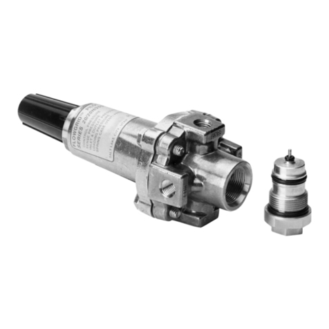
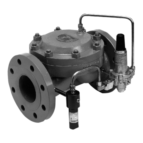
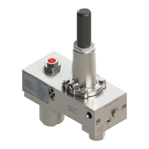
Baker Hughes Mooney FlowMax HP User manual

Mooney™
FlowMax™HP Regulator
Instruction Manual
Baker Hughes Data Classication : Public

ii | Baker Hughes Copyright 2021 Baker Hughes Company. All rights reserved.
THESE INSTRUCTIONS PROVIDE THE CUSTOMER/OPERATOR WITH IMPORTANT PRO-
JECT-SPECIFIC REFERENCE INFORMATION IN ADDITION TO THE CUSTOMER/OPERATOR’S
NORMAL OPERATION AND MAINTENANCE PROCEDURES. SINCE OPERATION AND MAINTE-
NANCE PHILOSOPHIES VARY, BAKER HUGHES COMPANY (AND ITS SUBSIDIARIES AND AF-
FILIATES) DOES NOT ATTEMPT TO DICTATE SPECIFIC PROCEDURES, BUT TO PROVIDE BA-
SIC LIMITATIONS AND REQUIREMENTS CREATED BY THE TYPE OF EQUIPMENT PROVIDED.
THESE INSTRUCTIONS ASSUME THAT OPERATORS ALREADY HAVE A GENERAL UNDER-
STANDING OF THE REQUIREMENTS FOR SAFE OPERATION OF MECHANICAL AND ELEC-
TRICAL EQUIPMENT IN POTENTIALLY HAZARDOUS ENVIRONMENTS. THEREFORE, THESE
INSTRUCTIONS SHOULD BE INTERPRETED AND APPLIED IN CONJUNCTION WITH THE
SAFETY RULES AND REGULATIONS APPLICABLE AT THE SITE AND THE PARTICULAR RE-
QUIREMENTS FOR OPERATION OF OTHER EQUIPMENT AT THE SITE.
THESE INSTRUCTIONS DO NOT PURPORT TO COVER ALL DETAILS OR VARIATIONS IN
EQUIPMENT NOR TO PROVIDE FOR EVERY POSSIBLE CONTINGENCY TO BE MET IN CON-
NECTION WITH INSTALLATION, OPERATION OR MAINTENANCE. SHOULD FURTHER INFOR-
MATION BE DESIRED OR SHOULD PARTICULAR PROBLEMS ARISE WHICH ARE NOT COV-
ERED SUFFICIENTLY FOR THE CUSTOMER/OPERATOR’S PURPOSES THE MATTER SHOULD
BE REFERRED TO BAKER HUGHES.
THE RIGHTS, OBLIGATIONS AND LIABILITIES OF BAKER HUGHES AND THE CUSTOMER/
OPERATOR ARE STRICTLY LIMITED TO THOSE EXPRESSLY PROVIDED IN THE CONTRACT
RELATING TO THE SUPPLY OF THE EQUIPMENT. NO ADDITIONAL REPRESENTATIONS OR
WARRANTIES BY BAKER HUGHES REGARDING THE EQUIPMENT OR ITS USE ARE GIVEN
OR IMPLIED BY THE ISSUE OF THESE INSTRUCTIONS.
THESE INSTRUCTIONS ARE FURNISHED TO THE CUSTOMER/OPERATOR SOLELY TO AS-
SIST IN THE INSTALLATION, TESTING, OPERATION, AND/OR MAINTENANCE OF THE EQUIP-
MENT DESCRIBED. THIS DOCUMENT SHALL NOT BE REPRODUCED IN WHOLE OR IN PART
WITHOUT THE WRITTEN APPROVAL OF BAKER HUGHES.

Mooney FlowMax HP Regulator Instruction Manual | 1
Copyright 2021 Baker Hughes Company. All rights reserved.
Table Of Contents
Product Description ....................................................................................................................... 1
Principles of Operation.................................................................................................................. 2
Nameplate Information................................................................................................................... 3
Regulator Markings........................................................................................................................ 3
Cross section graphic and part descriptions .............................................................................. 4
Installation....................................................................................................................................... 4
Piping Schematics.......................................................................................................................... 5
Start-up and Operation ................................................................................................................ 10
Maintenance.................................................................................................................................. 13
Bolt Torque Specications .......................................................................................................... 20
Troubleshooting ........................................................................................................................... 20
Scope
This manual provides instructions for the Installation, Operation,
and Maintenance of the Mooney FlowMax HP Regulator
(instructions for the standard FlowMax and the Series 22 Pilot
can be found in separate manuals). This manual is divided into
the following sections:
Product Description
The Mooney FlowMax HP is an easy to maintain regulator
designed to be used with a self-contained pilot system. The
Mooney FlowMax HP regulator has several unique features that
add to its versatility, such as:
• In-line maintenance
• A single maximum pressure rating for all components
• One actuator for all pressures and differentials
• A compact, low-volume actuator housing for quick response
• Top-entry design
• Maximum flow at a low differential
• Increased closing force with an increase in inlet pressure
Materials of Construction
Body ASTM A 216 WCB Steel
Actuator Housing ASTM A 516 Gr 70 Steel
Plug Seal Nitrile
Diaphragm Nitrile/Nylon
O-Ring & Seals Nitrile
Bolting ASTM B7
Spring Music Wire
Trim Stainless Steel
Seal Pack Housing Stainless Steel
Table 1 - Materials of Construction

2 | Baker Hughes Copyright 2021 Baker Hughes Company. All rights reserved.
Specifications Imperial Metric
Sizes 2,3,4, and 6 inch DN 50, DN 80, DN
100, DN 150
Body Style Single Port Single Port
End Connections 300 CL RF,
600 CL RF Flanged
Temperature
Working
Emergency
-20°F to 150°F
-40°F to 175°F
-29°C to 66°C
-40°C to 80°C
Maximum
Operating
Differential
1300 psi 90 bar
Maximum
Casing
Pressure
1480 psi 102 bar
Minimum
Differential
(Fully Open)
12 psi 0.83 bar
Outlet Pressure
Range
Series 22:
3 - 900 psi
0.21 - 62 bar
Maximum Inlet
Pressure
1480 psig
(limited by flange
or pilot rating)
102 bar
(limited by flange or
pilot rating)
Pilot Supply
Body Tap
Two 1/4” - 18 NPTF Two 1/4” - 18 NPTF
Sense Line Tap Three 1/4” - 18 NPTF Three 1/4” - 18 NPTF
Table 2 - Specifications
Figure 1 - Typical Pressure Reducing Regulator Flow Schematic
Principle of Operation
(Refer to Figure 1)
When the downstream pressure is greater than the set point of
the pilot, the pilot is closed, resulting in equal pressure above and
below the main diaphragm. With a balancing plug area slightly
larger than the seat area, the resulting closing force, along with
the force of the main spring, forces the plug against the seat.
With an increase in demand, the outlet pressure will begin to
drop and decrease the pressure above the main diaphragm. A
drop of outlet pressure below the pilot set point will cause the
pilot to open.
As the pilot opens, pressure increases underneath the main
diaphragm faster than pressure can bleed through the restrictor.
The imbalance in pressure on the main diaphragm overcomes
the spring force and the additional closing force from the
balanced plug, causing the plug to rise off the seat and satisfy
the flow demand.
Once the flow demand is satisfied and the downstream pressure
begins to increase, the pressure above the main diaphragm and
in the pilot sense cavity rises. This causes the pilot to close. The
pressure below the main diaphragm bleeds through the restrictor
until pressure equalizes above and below the main diaphragm.
The forces of the main spring and the balanced plug then close
the plug on the seat.

Mooney FlowMax HP Regulator Instruction Manual | 3
Copyright 2021 Baker Hughes Company. All rights reserved.
Nameplate Information
Figure 2 - Nameplate
Regulator Markings
Item Definition
FlowMax HP Trademarked name
FM FlowMax product identification
S/N Serial number assigned to regulator
Size Line size of body
Year Date of manufacture
CL Pressure rating class
Max Inlet Maximum inlet pressure psi/bar
Max. Differential Maximum allowable differential
pressure
Min. Differential Minimum differential required
to fully open regulator
Max. Temperature Maximum operating temperature
in degrees Fahrenheit/Celsius
Min. Temperature Minimum operating temperature
in degrees Fahrenheit/Celsius
Bolt Torque Torque requirement of actuator bolts
1. American National Standards Institute (ANSI) pressure class rating of the regulator.
2. Line size of body.
3. ANSI pressure class rating of the flange.
4. Indication that the regulator has been hydrostatically tested according to code requirements.
5. The Serial Number is stamped on the Body.
6. The Nameplate location.
7. Cage Identifier (not shown - generally attached as a bolt tag)
Figure 3 - Regulator Markings

4 | Baker Hughes Copyright 2021 Baker Hughes Company. All rights reserved.
Hydrostatic Testing
Installation and testing of the FlowMax HPRegula-
tor should be made by trained, qualied personnel
familiar with high pressure piping and pilot operated
regulators.
All FlowMax HP regulators are hydrostatically tested at the
factory prior to shipment according to ISA-S75.19 and EN 334
standards. If it is necessary to retest the Regulator body, follow
the procedures listed below.
Note: This Procedure applies to the regulator body only. If
actuator retesting is required, contact the factory for proper
procedures.
1. Disconnect and remove the pilot inlet, actuator sense control
line(s) and loading lines.
2. Remove the body-to-actuator bolts and remove the actuator
and pilot.
3. Plug the pilot supply line in the regulator body or, if applicable,
the pilot filter.
4. Plug the flange/actuator mounting surface on the body.
Note: A plug for hydrostatically testing the Body is available
from the factory.
6. Pressurize the system to the required maximum hydrostatic
pressure.
7. After the hydrostatic test is completed and the body is dry and
clean, follow the assembly procedures in the maintenance
section of this manual.
Installation
Personal injury, equipment damage, or leakage due to
explosion of accumulated gas or bursting of pressure
containing parts may result if this regulator is over
pressured or is installed where service conditions
could exceed the limits given in the specication of
this manual or on the nameplate, or where conditions
exceed any ratings of the adjacent piping or piping
connections. Verify the limitations of both regulator
and pilot to ensure neither device is over pressured.
To reduce the chances of such injury or damage,
provide pressure relieving or pressure limiting de-
vices (as required by the U.S. code of Federal Regula-
tions, by the National Fire Codes of the National Fire
Protection Association, or by other applicable codes)
to prevent service conditions from exceeding those
limits. Additionally, physical damage to the regulator,
pilot, or tubing can cause personal injury and/or prop-
erty damage due to explosion of accumulated gas. To
reduce the chances of such injury and damage, install
the regulator in a safe location.
1. Personnel: Installation of the FlowMax HP regulator should
be performed by trained, qualified personnel familiar with
high-pressure piping and pilot- operated regulators.
2. Prior Inspection: Inspect the main regulator, pilot, and
tubing for any damage that might have occurred in shipping.
Make sure the body, pilot sense lines, and piping are clear
and free of foreign material.
3. Flanged End Regulators: Use suitable line gaskets and
good bolting practices with flanged bodies. Incremental
tightening of the line bolts in a crisscross pattern is
recommended.
Gas regulators installed in conned or enclosed
spaces should be provided with adequate ventilation
to prevent the possibility of gas buildup or accumu-
lation from leaks and venting. Leaks or vented gas
may accumulate causing personal injury, death, or
property damage. Pilot spring cases and the regulator
enclosure should be vented to a safe area away from
air intakes, or any hazardous location. The vent lines
and stacks must be protected against condensation
and clogging.
Mooney FlowMax HP Regulator Instruction Manual | 5
Copyright 2021 Baker Hughes Company. All rights reserved.
4. Orientation: The FlowMax HP regulator may be installed
in any position – the best position being the one that
provides easiest access for pilot adjustment and general
maintenance.
5. Control Lines: Control (sense) lines should be run from
the FlowMax HP actuator to a point at least 8 to 10 pipe
diameters downstream from the regulator (refer to piping
schematics). Use Table 4 as a guide for the ideal tubing size
to use. Reduce as necessary to connect the actuator.
Outlet Pressure
Pilot
Regulator
with:
2 to 5 psi
(0.14 - 0.35
bar)
Greater than
5 psi (0.35
bar)
Static
Sense Line 1/2” Tubing 3/8” Tubing
Sense Line
with Flow 1/2” Tubing 1/2” Tubing
Table 3 - Outlet Pressure
Note: The control line connection should be away from
areas of turbulence (such as valves, reducers, and
elbows) and should have a full opening into the pipe
free from burrs, drill peels, and weld slag. Shut-off
valves may be required in the control line(s), if installed,
they should be of the full opening type. Gas velocity at
the sense line connection should not exceed 100 ft/sec
(30m/sec).
7. Pilot Supply Lines: Run a 3/8-inch or 1/2-inch pilot supply
line from the upstream piping or from the Inlet port body
connection on the side of the FlowMax HP regulator to the
pilot Inlet port.
8. A Filter in the pilot supply line is recommended to remove
particulates from the pilot supply that could affect the
variable orifice in the pilot.
Note: A shut-off valve is not required in the pilot supply
line, but if one is installed, it must be a full-opening
type.
9. Vent Valves and Gauge Connections: Vent valves and
gauge connections are recommended in the Inlet and
actuator sense piping of the FlowMax HP regulator.
10. Interstage Piping: The recommended length of the
interstage piping between monitor regulators is 6 pipe
diameters or 36 inches (915 mm), whichever is greater. It is
also recommended that the interstage piping be swaged up
1 pipe diameter over the nominal port size of the regulator
for working monitor applications.
For example: A station with two 2” FlowMax HP regulators
in a working monitor configuration should have interstage
piping at least 36 inches (915 mm) in length and swaged up
to a 3-inch pipe.
Piping Schematics
The following piping schematics are provided:
1. Single Regulator with Single Pilot ..............................Page 6
2. Stand-by Monitor (Monitor located downstream) .......Page 7
3. Stand-by Monitor (Monitor located upstream) ...........Page 8
4. Working Monitor set ...................................................Page 9
All drawings show installations with the Series 22 Pilot. Consult
factory for installation schematics of other manufacturer’s pilot
on the FlowMax HP regulator.

6 | Baker Hughes Copyright 2021 Baker Hughes Company. All rights reserved.
Piping Schematics (cont’d)
1. Single Regulator/Single Pilot (Pressure Reducing Regulator)
1. Pilot supply tubing from filter OUTLET connection to the Series 22 pilot INLET port.
2. Type 30 filter mounted in inlet piping.
3. LOADING port of Series 22 pilot connected to Loading connection on the actuator housing of the FlowMax HP regulator
4. Sense line connecting the SENSE Port on the Series 22 pilot to the sense port on the FlowMax HP actuator.
5. Sense line connecting the FlowMax HP regulator to the downstream piping. (Refer to Table 4 on Page 5 for sense piping
recommendations)
6. Series 22 pilot with pilot cartridge in PRV mode.

Mooney FlowMax HP Regulator Instruction Manual | 7
Copyright 2021 Baker Hughes Company. All rights reserved.
1. Pilot supply tubing from filter OUTLET to Series 22 pilot INLET port.
2. Type 30 Filter mounted in inlet piping.
3. LOADING Port of Series 22 pilot connected to the loading connection on the actuator housing of the FlowMax HP regulator.
4. Sense line connecting the SENSE port on the Series 22 pilot to the sense port on the FlowMax HP actuator.
5. Sense line connecting the FlowMax HP regulator to the downstream piping. (Refer to Table 4 on Page 5 for sense piping
recommendations)
6. Series 22 pilot with pilot cartridge in PRV mode.
7. Pilot supply tubing from filter OUTLET to Series 22 pilot INLET port.
8. Type 30 filter mounted in inlet piping.
9. LOADING port of Series 22 pilot connected to the Loading connection on the actuator housing of the FlowMax HP regulator.
10. Sense line connecting the SENSE port on the Series 22 pilot to the sense port on the FlowMax HP actuator.
11. Sense line connecting the FlowMax HP actuator to the downstream piping.
12. Series 22 pilot with pilot cartridge in PRV mode.
Piping Schematics (cont’d)
2. Stand-by Monitor (Monitor located downstream)

Piping Schematics (cont’d)
3. Stand-by Monitor (Monitor located upstream)
8 | Baker Hughes Copyright 2021 Baker Hughes Company. All rights reserved.
1. Pilot supply tubing from filter OUTLET connection to Series 22 pilot INLET port.
2. Type 30 filter mounted in inlet piping.
3. LOADING port of Series 22 pilot connected to the Loading connection on the actuator housing of the FlowMax HP regulator.
4. Sense line connecting the SENSE port on the Series 22 pilot to the sense port on the FlowMax HP actuator.
5. Sense line connecting the FlowMax HP actuator to the downstream piping. (Refer to Table 4 on Page 5 for sense piping
recommendations)
6. Series 22 pilot with pilot cartridge in PRV mode.
7. Pilot supply tubing from filter OUTLET connection to Series 22 Pilot INLET port.
8. Type 30 filter mounted in inlet piping.
9. LOADING port of Series 22 pilot connected to Loading connection on the actuator housing of the FlowMax HP regulator.
10. Sense line connecting SENSE port on Series 22 pilot to the sense port on the FlowMax HP actuator.
11. Sense line connecting the FlowMax HP actuator to the downstream piping.
12. Series 22 pilot with pilot cartridge in PRV mode.

Piping Schematics (cont’d)
4. Working Monitor Set
1st stage
regulator
2nd stage
regulator
Mooney FlowMax HP Regulator Instruction Manual | 9
Copyright 2021 Baker Hughes Company. All rights reserved.
1. Pilot supply tubing from filter OUTLET connection to Series 22 pilot (#1) INLET port.
2. Type 30 filter mounted in the inlet piping.
3. Pilot #2 LOADING port connected to the loading connection on the actuator housing of the FlowMax HP regulator.
4. Sense line connecting the 1st stage FlowMax HP regulator to the interstage piping. (Refer to Table 4 on Page 5 for sense piping
recommendations)
5. Sense line connecting SENSE port on Series 22 pilot (#2) to the sense port on the FlowMax HP actuator.
6. Series 22 pilot with pilot cartridge in PRV mode.
7. Pilot supply tubing from filter OUTLET connection to Series 22 pilot (#3) INLET port.
8. Sense line connecting the SENSE port on the monitor pilot (#2) to the downstream piping.
9. Sense line connecting SENSE port on Series 22 pilot (#3) to the sense port on the FlowMax HP actuator.
10. LOADING port of Series 22 pilot (#3) connected to the loading connection on the actuator housing of the FlowMax HP regulator.
11. Sense line connecting the 2nd stage FlowMax HP regulator to the downstream piping.

10 | Baker Hughes Copyright 2021 Baker Hughes Company. All rights reserved.
Start-up and Operation
The following procedures are suggested for start-up of the FlowMax
HP regulator equipped with Series 22 pilots. Start-up of the FlowMax
HP regulator should be made by trained, qualified personnel familiar
with high pressure systems and pilot-operated regulators.
The instruction manual for the PILOT(S) being used
should be consulted to insure that the installation and
start-up instructions for the pilot are followed. Some
equipment can be damaged if not installed and put
into operation correctly.
Single Pressure Reducing Regulator
1. Back off the pilot adjusting screw to fully remove the spring
compression.
2. Slowly open the upstream block valve to pressurize the
FlowMax HP regulator and pilot system. The regulator should
lock up (shut off) with zero pressure downstream.
3. Fully open any hand valve(s) in the control line(s) and the pilot
supply line.
4. Slightly open a downstream block valve or open a vent in piping
downstream of the FlowMax HP regulator.
5. Slowly increase the pilot spring setting until the desired
downstream pressure is achieved.
6. Slowly close the downstream block valve or vent to check the
FlowMax HP regulator for lockup (shut off).
7. Slowly open the downstream block valve to allow full flow.
Stand-by Monitor
(Upstream Operating Regulator
Configuration)
This procedure is based on the first regulator being the Operating
regulator and the second regulator being the Monitor regulator.
Note: In this configuration, installation of a shut-off valve and
a vent valve are required in the sense line of the operating
regulator to facilitate testing of the monitor regulator
performance. See Page 7.
1. If necessary, purge any pressure in the station.
2. Set operating regulator pilot (#1) spring at the MAXIMUM
setting. The sense line shut-off valve should be closed and the
sense line vent valve should be open.
3. Set monitor pilot (#2) spring to the MINIMUM (zero) setting.
4. Slowly open the inlet block valve. Full inlet pressure should
be present at the monitor regulator and the Monitor regulator
should be closed.
5. Open any hand valve(s) in the pilot supply lines on both
regulators. The sense line shut-off valve should remain closed
and the sense line vent valve should remain open (Refer to
page 7).
6. Open a vent or downstream block valve.
7. Increase the pilot spring setting of the monitor regulator until
the desired monitor override setting is reached. Lock in the
pilot setting.
8. With some flow going through the station, close the vent valve
on the operating regulator sense line and open the shut-off
valve on the same line. Start to lower the Pilot setting of the
operating regulator until the desired outlet pressure is achieved.
Note: When the set point of the operating regulator becomes
less than the set point of the monitor regulator, the interstage
pressure will drop from approximately full inlet pressure to
5-10 psi (0.34-0.68 bar) above the outlet pressure at low flow
rates.
Checking Stand-by Monitor Operation
1. With flow going through the station, slowly open the vent valve
installed in the operating regulator sense line while closing
the shut-off valve in the same line. The outlet pressure should
begin to rise as the operating regulator goes wide open. When
the pressure reaches the setpoint of the monitor regulator, the
monitor should take control and the interstage pressure should
increase to approximately full inlet pressure.
2. Return the system to normal operation by reversing the process
with the vent valve being closed while the shut-off valve is
returned to the open position. The interstage pressure should
drop to 5-10 psi (0.34-0.68 bar) above the outlet pressure as the
operating regulator regains control (at low flows).
Stand-by Monitor
(Upstream Monitor Regulator
Configuration)
This procedure is based on the first stage regulator being the Monitor
regulator and the second stage regulator being the Operating
regulator.
1. If necessary, purge any pressure in the station.
2. Set first stage monitor regulator pilot spring at the MAXIMUM
setting.
3. Set second stage operating regulator pilot spring to the
MINIMUM (zero) setting.
4. Slowly open the inlet block valve. Full inlet pressure should be
present at the second stage operating regulator and it should be
closed.
5. Fully open any hand valve(s) in the control line(s) and the pilot
supply line.
6. Open a vent or downstream block valve.
7. Increase the set point of the second stage operating regulator to
the desired monitor over-ride set pressure.
8. Decrease the pilot spring setting of the first stage monitor
regulator until it takes control at a set point just below the final
desired monitor over-ride set pressure.
9. Increase the second stage operating regulator to the maximum
pilot setting.
10. Increase the first stage monitor regulator set pressure to the
final desired monitor over-ride set point.
11. Decrease the pilot spring setting of second stage operating
regulator until the final set point is achieved.
Note: When the set point of the operating regulator
becomes less than the set point of the monitor regulator,
the interstage pressure will rise to 5-10 psi (0.34-0.68 bar)
below the full inlet pressure (at low flows).

Mooney FlowMax HP Regulator Instruction Manual | 11
Copyright 2021 Baker Hughes Company. All rights reserved.
Checking Stand-by Monitor Operation
1. With flow going through the station, slowly increase the setting
of the operating regulator. When the pressure reaches the
setpoint of the monitor regulator, the monitor should take control
and the interstage pressure should decrease to approximately
5-10 psi (0.34-0.68 bar) above the outlet pressure.
2. Reduce the setting of the operating regulator back to the
required outlet pressure. The interstage pressure should
increase to 5-10 psi (0.34-0.68 bar) below the inlet pressure as
the operating regulator regains control (at low flows).
Working Monitor
1. Purge any pressure in the station.
2. Set pilots #1 and #2 to a setting above the desired set points.
3. Set the pilot (#3) at a zero setting.
4. Slowly open the inlet block valve to station. The second stage regulator should remain closed as a result of the pilot #3 being set to zero.
5. Fully open any hand valve(s) in the control line(s) and the pilot supply line.
6. Open an outlet block valve or vent to allow flow through the station.
7. Increase the setting of the second stage regulator, pilot (#3) to the desired monitor over-ride pressure set point of the station.
8. Lower the setpoint of the first stage regulator pilot (#1) to the desired interstage pressure setting. The first stage regulator should begin
to control the interstage pressure at the setpoint of Pilot #1.
9. Lower the setpoint of pilot #2 to take control of the system (a pressure that will be slightly lower than the final monitor over-ride pressure).
10. Raise the setpoint of pilot #3 to a maximum setting.
11. Raise the setpoint of pilot #2 to maintain the exact monitor over-ride pressure set point.
12. Lower pilot #3 to the desired station outlet pressure.

12 | Baker Hughes Copyright 2021 Baker Hughes Company. All rights reserved.
Maintenance
1.0 Partial Disassembly for Plug/Seat
Insert and Plug/Seat Inspection and
Replacement
1.1 Disconnect all tubing to the Actuator. The Series 22 Pilot
block can remain attached to the Adapter Housing and
does not need to be removed for this procedure.
1.2 With the exception of the four cap screws that are
recessed into the Upper Actuator Housing, loosen and
remove the remaining cap screws that hold the Actuator
housing to the Adapter housing.
1.3 Use lifting eyes to remove the Actuator assembly by
lifting straight up. DO NOT PRY.
1.4 The adapter housing does not need to be removed.
1.5 Inspect the Seat Insert and Plug Seal for nicks, scratches
or other damage that may be visible.
1.6 If necessary, the Plug assembly can be disassembled at
this point and the Seat Insert can be replaced.
1.7 To disassemble the Plug assembly, remove the Cotter
Pin as shown in the figure below and loosen the Castle

Mooney FlowMax HP Regulator Instruction Manual | 13
Copyright 2021 Baker Hughes Company. All rights reserved.
Nut on top of the Plug. Be sure to use a wrench on the
Stem flats to avoid twisting the Stem assembly during
removal of the Castle Nut.
1.8 Once the Castle Nut is loosened, the Plug and Castle
Nut can be moved up the Stem and the Set screw on the
Plug skirt will be exposed.
1.9 After loosening the Plug skirt Set screw, the Plug skirt
can be unscrewed from the Stem and the Seat Insert can
be replaced. Be sure to use wrench flats on Plug skirt
and Stem to avoid twisting the Stem assembly.
2.0 Partial assembly for Plug/Seat
Insert Inspection and Replacement
2.1 With the Plug and Castle Nut slid up on the Stem, place
the new Seat Insert onto the Plug skirt and screw the
Plug skirt onto the Stem until tight. Tighten as per Table 5
2.2 Tighten the Plug skirt set screw and slide the Plug
against the Seat Insert.
2.3 Slid the Castle Nut down the shaft and engage threads.
The Castle Nut can be tightened by hand but, prior to
wrench tightening, place a separate wrench on the Stem
wrench flats to prevent rotation while tightening the
Castle Nut.
2.4 Tighten the Castle Nut to the torque as listed in Table 5
noting that the Castle Nut must line up with the hole in
the Stem for proper insertion of the Cotter Pin.
2.5 Insert Cotter Pin and bend the ends at least 90 degrees
to maintain proper locking action.

14 | Baker Hughes Copyright 2021 Baker Hughes Company. All rights reserved.
2.6 If replacing the Plug Seal, install it at this time. The
Plug Seal consists of three components and should be
installed as noted in the figure below –
2.7 Prior to reinstalling the Actuator assembly onto the
Adapter housing, clean and inspect the Adapter housing
O-ring and groove as noted below. Replace if necessary.
2.8 Apply Parker™ O-lube to the Wedgepak seals on the
Plug Seal and the Adapter O-ring prior to lowering the
Actuator into position.
2.9 While lowering the Actuator Housing, care should be
taken to assure that the unit is centered and that the Plug
Seal slides properly into place as the unit is lowered.
2.10 The inner diameter of the Adapter Housing has a slight
taper which acts to compress the Plug Seal as it slides
into place.
2.11 A slight clicking sound can be heard as the plug seal
transitions from the Adapter housing into the valve Cage.
2.12 Once the Actuator is properly seated, the Cap Screws
can be re-installed and torqued to specified levels (see
Table 5). Always torque the Cap Screws in a crisscross
pattern.
2.13 Reconnect the tubing.
2.14 Pressure test for leaks prior to returning to service.
O-ring Groove

Mooney FlowMax HP Regulator Instruction Manual | 15
Copyright 2021 Baker Hughes Company. All rights reserved.
3.0 Diaphragm and Seal Pack
Inspection and Replacement
Note: The procedure assumes that the Lower Actuator
Housing will remain on the Adapter throughout the
process. Disassembly and Inspection can also be
performed with the Actuator assembly removed as
described in Section 1.0. Care should be taken to protect
the Stem and Plug if removed from the Adapter housing to
prevent bending and any other damage.
3.1 Disconnect the Sense and Loading tubing to the
Actuator. The Series 22 Pilot block can remain attached
to the Adapter housing and does not need to be removed
for this procedure.
3.2 Remove all the Cap Screws holding the Upper Actuator
Housing to the Lower Actuator Housing.
3.3 Disconnect Travel Indicator shaft from Stem by pressing
down on shaft and rotating in a counter-clockwise direction.
Travel Indicator Stem should be free to move up and down.
3.4 Using proper lifting points, lift the Upper Actuator Housing
off the unit.
3.5 Remove the Spring and Travel Indicator shoe. The Travel
Indicator shoe is threaded onto the Stem.
3.6 Remove the upper Cotter Pin.
3.7 While using the wrench flats on the top of the Stem to
hold it in place, unscrew the upper Castle Nut from the
Stem.
3.8 Remove the Upper Diaphragm Support plate.
Note: The Upper Diaphragm Support plate has
an internal O-ring that should be inspected and
replaced if necessary.

16 | Baker Hughes Copyright 2021 Baker Hughes Company. All rights reserved.
3.9 Remove the Diaphragm and inspect for any bubbles,
cracking or other damage that may be present. Replace
if necessary.
3.10 Remove the Lower Diaphragm Support plate.
Note: The Lower Diaphragm Support plate also has an
internal O-ring that should be inspected and replaced if
necessary.
3.11 The Seal Pack is held in place by four Cap Screws.
Remove the four Cap Screws and remove the Cover
Plate. Two threaded holes are used for jacking or lifting
the Seal Pack out as a complete unit.
3.12 Thread two of the Seal Pack cap screws into the extra
holes and tighten to lift the Seal Pack out of the Lower
Actuator Housing.
3.13 Due to the difficulty in replacing the Seal Pack’s internal
Stem Seal, it is recommended that the Seal Pack be
replaced as a complete unit.
3.14 If inspection of Plug Seal and Seat Insert are being
performed, the Lower Diaphragm Housing can be
removed - exposing the Plug assembly.
3.15 If Lower Diaphragm Housing is difficult to remove, two
cover bolts may be inserted into opposite threaded holes
on the Housing and used as jacking screws.
3.16 Attach Lift Eyes to two threaded holes in housings and lift
vertically.
3.17 Inspect and replace O-ring in Adapter Housing.
3.18 Plug assembly may be removed by lifting Stem. Plug will
experience a click when the Plug Seal transitions from
the cage to the Adapter Housing. Force may be required
to move the Plug assembly past this point.
Note: Adapter Housing does not need to be removed.
3.19 Remove Cotter Pin and remove the Castle Nut.
3.20 Remove Plug. Set Screw in Plug Skirt does not need to
be removed.
3.21 Replace Seat Insert.
3.22 Replace Plug.
3.23 Install Castle Nut and tighten as per Table 5. Use wrench
flats to hold part and prevent the assembly from turning.
3.24 Install Cotter Pin and deform at least 90 degrees for
proper locking.
Threaded
Jacking Hole

Mooney FlowMax HP Regulator Instruction Manual | 17
Copyright 2021 Baker Hughes Company. All rights reserved.
3.25 Apply Parker o-lube and install Plug assembly into Cage.
Plug will stick at transition, keep pushing.
3.26 Install Lower Diaphragm Housing.
3.27 Assembly is done in the reverse order. Lube all O-rings
with Parker O-lube prior to reassembly.
3.28 Install Seal Pack Housing by sliding Seal Pack assembly
onto Stem and then sliding into the Lower Diaphragm
Housing. Install Seal Pack Cover.
Note: The Stem has a taper which allows for easy
installation of the Stem Seals.
3.29 Torque the Seal Pack Cap Screws to specified levels
(see Table 5) and manually move the Stem through a few
cycles to assure proper alignment prior to attaching the
Diaphragm and Diaphragm Support Plates.
3.30 Install Lower Diaphragm Support plate, Diaphragm, and
Upper Support plate.
3.31 Slide the Castle Nut onto the Stem shaft and engage
threads. The Castle Nut can be tightened by hand but,
prior to wrench tightening, place a separate wrench on
the Stem wrench flats to prevent rotation while tightening
the Castle Nut.
3.32 Tighten the Upper Castle to the torque as listed in Table
5 noting that the Castle Nut must line up with the hole is
the Stem for proper insertion of the Cotter Pin.
3.33 Insert Cotter Pin and bend the ends to at least 90
degrees to maintain proper locking action.
3.34 Thread the Travel Indicator shoe onto the Stem and
tighten while holding the stem from turning using a
wrench across the provided flats.
3.35 Set and center the Spring on the Upper Diaphragm
Support plate prior to lowering the Upper Actuator
Housing onto the assembly.
3.36 Ensure that the Diaphragm bead is sitting in the groove
of the Lower Actuator Housing.
3.37 Lower and bolt the Upper Actuator Housing to the
recommended torque specification.
3.38 Reattach the Travel Indicator by pressing down on the
Indicator stem and turning in clockwise direction. Travel
Indicator should be locked to the Stem and should not be
loose to move up and down.
3.39 Reconnect the Sense and Loading tubing.
3.40 Pressure test for leaks prior to returning to service.
4.0 Seat Ring and Cage Inspection
and Replacement
4.1 Disconnect the Inlet, Sense, and Loading tubing to the
Actuator. The Series 22 Pilot block can remain attached
to the Adapter Housing and does not need to be removed
for this procedure.
4.2 With the exception of the four Cap Screws that are
recessed into the Upper Actuator Housing, loosen and
remove the remaining Cap Screws that hold the Actuator
Housing to the Adapter Housing as shown below.
4.3 Remove the Actuator assembly by lifting straight up. DO
NOT PRY.

18 | Baker Hughes Copyright 2021 Baker Hughes Company. All rights reserved.
4.4 Remove the Adapter Housing Cap Screws and lift the
Adapter Housing using the provided lifting holes.
4.5 Remove the Upper Crush Gasket and lift the Cage from
the Body. Clean and inspect the Cage for any sign of
abrasive wear or damage.
4.6 Remove the Seat Ring and Lower Crush Gasket. Inspect
the Seat Ring for any sign of abrasive wear or damage.
Replace if necessary. Due to the close fit between the
Seat and Cage, the Seat may require prying to remove it
from the cage.
4.7 Insert Lower Crush Gasket.
Note: The two Crush Gaskets are not re-usable and
must be replaced if the Adapter Housing is removed
during teardown and reassembly.
4.8 Insert the Seat Ring, Cage and Upper Crush Gasket.
4.9 Position the Adapter Housing in place on top of the
Upper Crush Gasket and install Cap Screws.
Note: The torqueing of the Adapter Housing Cap
Screws is critical to setting the Upper and Lower
Crush Gaskets and must be done in an even
crisscross manner to provide even force for setting
the gaskets. Torque should be applied in intervals of
1/3 the final torque, 2/3 final torque and final torque.
4.10 Torque Adapter Housing Cap Screws to specified levels
(see Table 5).
4.11 Prior to reinstalling the Actuator assembly onto the
Adapter Housing, clean and inspect the Adapter Housing
O-ring as noted in the figure below. Replace if necessary.
4.12 Apply Parker O-lube to the Plug Seal and the Adapter
O-ring prior to lowering the Actuator into position.
4.13 While lowering the Actuator housing, care should be
taken to assure that the unit is centered and that the Plug
Seal slides properly into place as the unit is lowered.
4.14 The inner diameter of the Adapter Housing has a slight
taper which acts to compress the Plug Seal as it slides
into place.
4.15 A slight clicking sound can be heard as the Plug Seal
transitions from the Adapter Housing into the valve Cage.
4.16 Once the Actuator is properly seated, the Cap Screws
can be re-installed and torqued to specified levels (see
Table 5). Always torque the Cap Screws in a crisscross
pattern.
4.17 Reconnect the Inlet, Sense and Loading tubing.
4.18 Pressure test for leaks prior to returning to service.
Table of contents
Other Baker Hughes Controllers manuals

Baker Hughes
Baker Hughes Masoneilan 31 Series User manual

Baker Hughes
Baker Hughes Mooney 22 Series User manual

Baker Hughes
Baker Hughes Masoneilan 12400 Series User manual

Baker Hughes
Baker Hughes Masoneilan 78 Series User manual

Baker Hughes
Baker Hughes Masoneilan 525 Seris User manual

Baker Hughes
Baker Hughes Masoneilan 536V User manual

Baker Hughes
Baker Hughes Masoneilan 5A Series User manual

Baker Hughes
Baker Hughes Masoneilan 37 User manual

Baker Hughes
Baker Hughes Masoneilan SVI II ESD User manual

Baker Hughes
Baker Hughes Mooney Flowgrid User manual