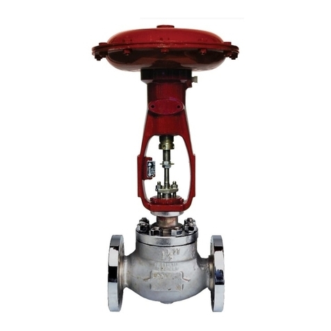
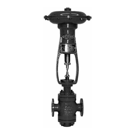
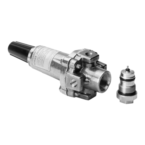
Baker Hughes Masoneilan 525 Seris User manual

Masoneilan™
525 & 526 Series
Reducing and Back Pressure Regulators
Instruction Manual (Rev.C)

Copyright 2020 Baker Hughes Company. All rights reserved.
THESE INSTRUCTIONS PROVIDE THE CUSTOMER/OPERATOR WITH IMPORTANT PROJECT-
SPECIFIC REFERENCE INFORMATION IN ADDITION TO THE CUSTOMER/OPERATOR’S
NORMAL OPERATION AND MAINTENANCE PROCEDURES. SINCE OPERATION AND
MAINTENANCE PHILOSOPHIES VARY, BAKER HUGHES COMPANY (AND ITS SUBSIDIARIES
AND AFFILIATES) DOES NOT ATTEMPT TO DICTATE SPECIFIC PROCEDURES, BUT TO
PROVIDE BASIC LIMITATIONS AND REQUIREMENTS CREATED BY THE TYPE OF EQUIPMENT
PROVIDED.
THESE INSTRUCTIONS ASSUME THAT OPERATORS ALREADY HAVE A GENERAL
UNDERSTANDING OF THE REQUIREMENTS FOR SAFE OPERATION OF MECHANICAL AND
ELECTRICAL EQUIPMENT IN POTENTIALLY HAZARDOUS ENVIRONMENTS. THEREFORE,
THESE INSTRUCTIONS SHOULD BE INTERPRETED AND APPLIED IN CONJUNCTION WITH
THE SAFETY RULES AND REGULATIONS APPLICABLE AT THE SITE AND THE PARTICULAR
REQUIREMENTS FOR OPERATION OF OTHER EQUIPMENT AT THE SITE.
THESE INSTRUCTIONS DO NOT PURPORT TO COVER ALL DETAILS OR VARIATIONS IN
EQUIPMENT NOR TO PROVIDE FOR EVERY POSSIBLE CONTINGENCY TO BE MET IN
CONNECTION WITH INSTALLATION, OPERATION OR MAINTENANCE. SHOULD FURTHER
INFORMATION BE DESIRED OR SHOULD PARTICULAR PROBLEMS ARISE WHICH ARE NOT
COVERED SUFFICIENTLY FOR THE CUSTOMER/OPERATOR’S PURPOSES THE MATTER
SHOULD BE REFERRED TO BAKER HUGHES.
THE RIGHTS, OBLIGATIONS AND LIABILITIES OF BAKER HUGHES AND THE CUSTOMER/
OPERATOR ARE STRICTLY LIMITED TO THOSE EXPRESSLY PROVIDED IN THE CONTRACT
RELATING TO THE SUPPLY OF THE EQUIPMENT. NO ADDITIONAL REPRESENTATIONS OR
WARRANTIES BY BAKER HUGHES REGARDING THE EQUIPMENT OR ITS USE ARE GIVEN
OR IMPLIED BY THE ISSUE OF THESE INSTRUCTIONS.
THESE INSTRUCTIONS ARE FURNISHED TO THE CUSTOMER/OPERATOR SOLELY TO
ASSIST IN THE INSTALLATION, TESTING, OPERATION, AND/OR MAINTENANCE OF THE
EQUIPMENT DESCRIBED. THIS DOCUMENT SHALL NOT BE REPRODUCED IN WHOLE OR IN
PART WITHOUT THE WRITTEN APPROVAL OF BAKER HUGHES.

Copyright 2020 Baker Hughes Company. All rights reserved.
Table of Contents
Safety Information.....................................................................................................................1
1. Introduction............................................................................................................................2
2. General ...................................................................................................................................2
3. Unpacking ..............................................................................................................................2
4. Installation..............................................................................................................................3
5. Adjustment.............................................................................................................................3
6. Body Disassembly.................................................................................................................3
6.1 525 (Reducing Service)....................................................................................................3
6.2 526 (Back Pressure Service) ...........................................................................................3
7. Maintenance & Repair...........................................................................................................4
.............................................................................................................4
7.2 Bushing Removal.............................................................................................................4
7.3 Lapping Seats ..................................................................................................................4
7.3.1 525 (Reducing Service) ...........................................................................................4
7.3.2 526 (Back Pressure Service)...................................................................................5
7.4 Pinning .............................................................................................................................5
7.5 Packing Box .....................................................................................................................5
...............................................................................6
8. Valve Body Reassembly .......................................................................................................6
8.1 525 (Reducing Service)....................................................................................................6
8.2 526 (Back Pressure Service) ...........................................................................................7
9. Actuators................................................................................................................................7
......................................................................................................7

Copyright 2020 Baker Hughes Company. All rights reserved.
Safety Information
Important - Please read before installation
DANGER, WARNING, and CAUTION
DANGER and
WARNING CAUTION
equipment can, under certain operational
conditions, result in degraded process system performance
that can lead to injury or death. Total compliance with all
DANGER, WARNING, and CAUTION
operation.
Note: Indicates important facts and conditions.
About this Manual
•
prior notice.
•
•
• Regulator
models 525 and 526
Useful Life Period
Regulator models
525 and 526
it is essential to conduct annual inspections, routine maintenance
Warranty
Baker Hughes recommended usages. Baker Hughes reserves
Note: Prior to installation:
•
•
•
•

Copyright 2020 Baker Hughes Company. All rights reserved.
1. Introduction
Serial Plate
After Sales Service
contact the local Baker Hughes Masoneilan representative or
Spare Parts
through local Masoneilan representatives or Masoneilan Parts
Department.
Actuator and Accessories
2. General
process applications.
3. Unpacking
2nd 3rd 4th1st
5. Regulator
Seat
5. Reducing Services(1)
6. Back Pressure
Services(2)
Body Series Plug Type Other Options

Copyright 2020 Baker Hughes Company. All rights reserved.
4. Installation
incorporated.
5. Adjustment
the regulator.
6. Body Disassembly
Prior to performing maintenance on the valve, isolate
the valve and vent the process pressure.
6.1 525 (Reducing Service)
Note: Spiral wound body gaskets (22) are standard in
the 500 Series design and it is imperative that a new
gasket be installed each time the valve is disassembled.
Care must be taken to avoid damage to the plug and
plug guide.
Figure 2.
Note: Spiral wound body gaskets (22) are standard in
the 500 Series design and it is imperative that a new
gasket be installed each time the valve is disassembled.
6.2 526 (Back Pressure Service)
Note: Spiral wound body gaskets (22) are standard in
the 500 Series design and it is imperative that a new
gasket be installed each time the valve is disassembled
Care must be taken to avoid damage to the plug and
upper bushing (23).
Figure 2.

Copyright 2020 Baker Hughes Company. All rights reserved.
7. Maintenance & Repair
7.1 Failure to shut off
7.2 Bushing Removal
7.3 Lapping Seats
Note: Lapping should produce a line contact area, not the
entire surface.
Before lapping, the plug and stem sub-assembly must
be concentric. (See pinning operation, section 8.4).
7.3.1 525 (Reducing Service)
cleaned.
Note: A sealant compatible with the process should be
applied sparingly to the seat ring threads and sealing
shoulder.
Do not over-tighten. Do not strike seat ring lugs di-
rectly. This could distort the seat ring resulting in seat
leakage.
Donottightennutstonaltorquespecicationsat
this time. The bonnet is used temporarily for guiding
purposes only.
Note: As an alternative, drill a hole through a flat steel
plate and fasten to the plug stem using two locknuts.
Note: The plug should be lifted and turned 90° each
time before repeating Step (9). This intermittent lifting
is required to keep the plug and seat rings concentric
during lapping.
Avoid over-lapping as this can cause damage to the
seating surface rather than improve leakage perfor-
mance.
Do not remove seat ring.
7.3.2 526 (Back Pressure Service)
cleaned.
Note: A sealant compatible with the process should be
applied sparingly to the seat ring threads and sealing
shoulder.

Copyright 2020 Baker Hughes Company. All rights reserved.
Do not over-tighten. Do not strike seat ring lugs di-
rectly. This could distort the seat ring resulting in seat
leakage.
Donottightennutstonaltorquespecicationsat
this time. The bonnet is used temporarily for guiding
purposes only.
Note: As an alternative, drill a hole through a flat steel
plate and fasten to the plug stem using two locknuts.
contact, and rotate the stem in short oscillating strokes
Note: The plug should be lifted and turned 90° each
time before repeating Step (9). This intermittent lifting
is required to keep the plug and seat rings concentric
during lapping.
Do not remove seat ring.
7.4 Pinning
Note: While pinning is being performed, care must be taken
not to damage the seating surface and plug guides.
Note: If it is necessary to drill out the pin, a drill
somewhat smaller than the pin should be used and the
remainder of the pin driven out.
Note: The area of the plug stem marked X in Figure 4
serves as a guide and must be checked to ensure a
close fit in the valve plug.
Note: This can be checked by measuring the depth of
the pilot recess in the plug (X in Figure 4), and making a
reference mark on the stem the same distance from the
thread. When properly assembled, the reference mark
should be flush with the end of the guide section.
drill, drill the stem using the hole in the plug as a guide.
on it and press into the hole.
Note: The pin must be recessed approximately 1/16”
below the plug guide surface.
Note: The plug should be placed in a collet with the plug
guide against it and the plug should be struck.
7.5 Packing Box
Valve must be isolated and the pressure vented be-
fore performing packing box maintenance.
7.5.1 Carbon/PTFE Rings (Standard)
Note: The Carbon/PTFE packing rings have a skive cut
allowing packing replacement without disconnecting the
plug stem from the actuator connector or actuator stem.
valve stem.
Note: These parts may be secured using tape or wire to
keep them out of the way before proceeding.
Copyright 2020 Baker Hughes Company. All rights reserved.
Note: On valves equipped with an optional lubricator
connection, the lantern ring (17) must also be removed
to gain access to lower packing rings.
D. Replace packing rings (16).
Note: Assemble and compress rings one at a time into
packing box. The skive cut of each packing ring must
be placed about 120 degrees apart.
Note: On valves equipped with an optional lubricator
connection, refer to Figure 2 for correct amount of rings
to place under the lantern ring (17).
F. Replace and tighten packing stud nuts (15).
Do not over tighten.
Note: In an emergency, string packing may be used as
a temporary repair only. It must be replaced with the
correct packing as soon as possible.
8. Valve Body Reassembly
Note: If any of the following steps were completed during
maintenance, then proceed to the next step.
8.1 525 (Reducing Service)
Note: A sealant compatible with the process should be
applied sparingly.
Do not over-tighten. Do not strike seat ring lugs
directly. This could distort the seat ring resulting in
unwarranted seat leakage.
Tighten nuts (10) until metal to metal contact is
obtained with proper bolt torque. Refer to Table 1 for
properbolttorqueandtighteningsequencespecica-
tions.
Note: Valve should be lapped before final assembly.
See Section 8.3.
Note: Spiral wound body gaskets (22) are standard in
the 500 Series design. It is imperative that a new gasket
be installed each time the valve is disassembled.
Tighten nuts (21) until metal to metal contact is
obtained with proper bolt torque. Refer to Table 1 for
properbolttorqueandtighteningsequencespecica-
tions.
I. lnsert packing (16) (and lantern ring (17) on valves equipped
optional designs.
Do not over tighten (See Section “8.5. Packing Box”).
8.2 526 (Back Pressure Service)
Note: A sealant compatible with the process should be
applied sparingly.
Do not over-tighten. Do not strike seat ring lugs
directly. This could distort the seat ring resulting in
unwarranted seat leakage.
Note: Valve should be lapped before final assembly. See
Section 8.3.

Copyright 2020 Baker Hughes Company. All rights reserved.
Note: Spiral wound body gaskets (22) are standard in
the 500 Series design. It is imperative that a new gasket
be installed each time the valve is disassembled.
Tighten nuts (21) until metal to metal contact is
obtained with proper bolt torque. Refer to Table 1 for
properbolttorqueandtighteningsequencespecica-
tions.
I. lnsert packing (16) (and lantern ring (17) on valves equipped
optional designs.
Do not over tighten (See Section “8.5. Packing Box”).
9. Actuators
9.1 Type 10900 Actuators
Figure 1a: Typical Reducing Application
Figure 1b: Typical Back Pressure Application
Figure 2: Lubricator Connection (Optional)
Figure 3: Seat Lapping Device

Copyright 2020 Baker Hughes Company. All rights reserved.
Figure 5: Bolt Tightening Sequence
Valve Size ANSI Class
Bolting
Requirements
Torque Requirements
Minimum Maximum Pre-Load
inch mm Qty Size (inch) Lbs.Ft N.m Lbs.Ft N.m Lbs.Ft N.m
¾ 6 25 34 55 75 5 7
6 25 34 55 75 5 7
125 6 25 34 55 75 5 7
6 25 34 55 75 5 7
1½ 6 25 34 55 75 5 7
6 25 34 55 75 5 7
2 8 25 34 55 75 5 7
8 25 34 55 75 5 7
3 8 45 61 89 14
8 45 61 89 14
4 8 27
8 27
Stem.
Dia. Hole Dia. “A” “B” “X”
inches in mm in mm in mm
4,78 31,75 12,7
5,56 1,562 39,67 15,7
6,35 1,875 47,63 19,1
1 7,92 25,4
Figure 4: Bolt Pinning Dimensions

Copyright 2020 Baker Hughes Company. All rights reserved.
525 Reducing Service 526 Back Pressure
Parts Reference
1 Bonnet 17
Upper Seat Ring 11 18 Plug Stem Locknut
12 19
Plug 13 Packing Flange 21
Plug Stem 14 Packing Stud
Plug Pin 15 23
9 Blind Head Packing

Copyright 2020 Baker Hughes Company. All rights reserved.
Notes

Copyright 2020 Baker Hughes Company. All rights reserved.
Notes

Copyright 2020 Baker Hughes Company. All rights reserved.
Notes

Tech Field Support & Warranty:
bakerhughes.com
Direct Sales Office Locations
Find the nearest local Channel Partner in your area:
Australia
Perth
Brazil
China
France
India
Italy
Japan
Korea
Malaysia
Mexico
Russia
Saudi Arabia
Singapore
South Africa
South & Central
America and the Caribbean
Spain
United Arab Emirates
United Kingdom
Bracknell
United States
This manual suits for next models
1
Table of contents
Other Baker Hughes Controllers manuals

Baker Hughes
Baker Hughes Mooney Flowgrid User manual

Baker Hughes
Baker Hughes Masoneilan 10900 Series User manual

Baker Hughes
Baker Hughes Masoneilan 31 Series User manual

Baker Hughes
Baker Hughes Masoneilan 5A Series User manual

Baker Hughes
Baker Hughes Masoneilan 525 User manual

Baker Hughes
Baker Hughes Masoneilan 536V User manual

Baker Hughes
Baker Hughes Masoneilan 12400 Series User manual

Baker Hughes
Baker Hughes Masoneilan SVI II ESD User manual

Baker Hughes
Baker Hughes Mooney 21 Series User manual

Baker Hughes
Baker Hughes Mooney 22 Series User manual