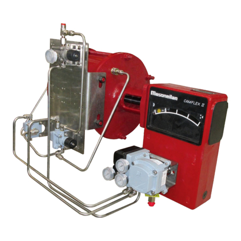
Baker Hughes Masoneilan 31 Series User manual

Baker Hughes Data Classication: Public
31/32/36 Series
Rotary Valve Actuator
Instruction Manual (Rev.A)

b | Baker Hughes Copyright 2023 Baker Hughes Company. All rights reserved.
THESE INSTRUCTIONS PROVIDE THE CUSTOMER/OPERATOR WITH IMPORTANT PROJECT-
SPECIFIC REFERENCE INFORMATION IN ADDITION TO THE CUSTOMER/OPERATOR’S
NORMAL OPERATION AND MAINTENANCE PROCEDURES. SINCE OPERATION AND
MAINTENANCE PHILOSOPHIES VARY, BAKER HUGHES COMPANY (AND ITS SUBSIDIARIES
AND AFFILIATES) DOES NOT ATTEMPT TO DICTATE SPECIFIC PROCEDURES, BUT TO
PROVIDE BASIC LIMITATIONS AND REQUIREMENTS CREATED BY THE TYPE OF EQUIPMENT
PROVIDED.
THESE INSTRUCTIONS ASSUME THAT OPERATORS ALREADY HAVE A GENERAL
UNDERSTANDING OF THE REQUIREMENTS FOR SAFE OPERATION OF MECHANICAL AND
ELECTRICAL EQUIPMENT IN POTENTIALLY HAZARDOUS ENVIRONMENTS. THEREFORE,
THESE INSTRUCTIONS SHOULD BE INTERPRETED AND APPLIED IN CONJUNCTION WITH
THE SAFETY RULES AND REGULATIONS APPLICABLE AT THE SITE AND THE PARTICULAR
REQUIREMENTS FOR OPERATION OF OTHER EQUIPMENT AT THE SITE.
THESE INSTRUCTIONS DO NOT PURPORT TO COVER ALL DETAILS OR VARIATIONS IN
EQUIPMENT NOR TO PROVIDE FOR EVERY POSSIBLE CONTINGENCY TO BE MET IN
CONNECTION WITH INSTALLATION, OPERATION OR MAINTENANCE. SHOULD FURTHER
INFORMATION BE DESIRED OR SHOULD PARTICULAR PROBLEMS ARISE WHICH ARE NOT
COVERED SUFFICIENTLY FOR THE CUSTOMER/OPERATOR’S PURPOSES THE MATTER
SHOULD BE REFERRED TO BAKER HUGHES.
THE RIGHTS, OBLIGATIONS AND LIABILITIES OF BAKER HUGHES AND THE CUSTOMER/
OPERATOR ARE STRICTLY LIMITED TO THOSE EXPRESSLY PROVIDED IN THE CONTRACT
RELATING TO THE SUPPLY OF THE EQUIPMENT. NO ADDITIONAL REPRESENTATIONS OR
WARRANTIES BY BAKER HUGHES REGARDING THE EQUIPMENT OR ITS USE ARE GIVEN
OR IMPLIED BY THE ISSUE OF THESE INSTRUCTIONS.
THESE INSTRUCTIONS ARE FURNISHED TO THE CUSTOMER/OPERATOR SOLELY TO
ASSIST IN THE INSTALLATION, TESTING, OPERATION, AND/OR MAINTENANCE OF THE
EQUIPMENT DESCRIBED. THIS DOCUMENT SHALL NOT BE REPRODUCED IN WHOLE OR IN
PART WITHOUT THE WRITTEN APPROVAL OF BAKER HUGHES.

Masoneilan 31/32/36 Series Rotary Actuator Instruction Manual | c
Copyright 2023 Baker Hughes Company. All rights reserved.
Table of Contents
Safety Information................................................................................................1
About this Manual ................................................................................................1
Useful Life Period.................................................................................................1
Warranty ................................................................................................................1
1. General ..............................................................................................................2
1.1 Product Description .......................................................................................................................................2
1.2 Serial Plate ....................................................................................................................................................2
1.3 After Sales Service ........................................................................................................................................2
1.4 Spare Parts ...................................................................................................................................................2
1.5 Valve and Actuator Accessories ....................................................................................................................2
2. Installation.........................................................................................................2
2.1 Cleanliness of Piping ....................................................................................................................................2
2.2 Isolating By-Pass Valve.................................................................................................................................2
3. Maintenance......................................................................................................3
3.1 Yoke and Housing Installation on Valve ........................................................................................................5
3.2 Spring Pack Assembly ..................................................................................................................................5
3.3 Diaphragm Power Head Assembly ..............................................................................................................6
3.4 Handwheel Assembly ...................................................................................................................................7
3.5 Assembly Adjustments .................................................................................................................................8
3.5.1 Lever Arm Adjustments .........................................................................................................................8
3.5.2 Travel Stop Adjustments ........................................................................................................................8
3.6 Final Assembly and Inspection .....................................................................................................................8

1 | Baker Hughes Copyright 2023 Baker Hughes Company. All rights reserved.
Safety Information
Important - Please read before installation
These instructions contain DANGER, WARNING, and CAUTION
labels, where necessary, to alert you to safety related or other
important information. Read the instructions carefully before
installing and maintaining your control valve. DANGER and
WARNING hazards are related to personal injury. CAUTION
hazards involve equipment or property damage. Operation
of damaged equipment can, under certain operational
conditions, result in degraded process system performance
that can lead to injury or death. Total compliance with all
DANGER, WARNING, and CAUTION notices is required for
safe operation.
CAUTION
CAUTION
WARNING
DANGER
This is the safety alert symbol. It alerts you to potential personal
injury hazards. Obey all safety messages that follow this symbol
to avoid possible injury or death.
CAUTION
CAUTION
WARNING
DANGER
Indicates a potentially hazardous situation which, if not avoided,
could result in death or serious injury.
CAUTION
CAUTION
WARNING
DANGER
Indicates a potentially hazardous situation which, if not avoided,
could result in serious injury.
CAUTION
CAUTION
WARNING
DANGER
Indicates a potentially hazardous situation which, if not avoided,
could result in minor or moderate injury.
CAUTION
CAUTION
WARNING
DANGER
When used without the safety alert symbol, indicates a potentially
hazardous situation which, if not avoided, could result in property
damage.
Note: Indicates important facts and conditions.
About this Manual
• The information in this manual is subject to change without
prior notice.
• The information contained in this manual, in whole or part,
shall not be transcribed or copied without Baker Hughes’s
written permission.
• Please report any errors or questions about the information
in this manual to your local supplier.
• These instructions are written specifically for the
Masoneilan™ Model 31/32/36 Series Rotary Actuator, and
do not apply for other valves outside of this product line.
Useful Life Period
The current estimated useful life period for the Model 31/32/36
Series Rotary Actuator is 25+ years. To maximize the useful
life of the product, it is essential to conduct annual inspections,
routine maintenance and ensure proper installation to avoid
any unintended stresses on the product. The specific operating
conditions will also impact the useful life of the product. Consult
the factory for guidance on specific applications if required prior
to installation.
Warranty
Items sold by Baker Hughes are warranted to be free from defects
in materials and workmanship for a period of one year from the
date of shipment provided said items are used according to
Baker Hughes recommended usages. Baker Hughes reserves
the right to discontinue manufacture of any product or change
product materials, design or specifications without notice.
Note: Prior to installation
• The actuator must be installed, put into service and
maintained by qualified and competent professionals who
have undergone suitable training.
• Under certain operating conditions, the use of damaged
equipment could cause a degradation of the performance
of the system which may lead to personal injury or death.
• Changes to specifications, structure, and components
used may not lead to the revision of this manual unless
such changes affect the function and performance of the
product.
Masoneilan 31/32/36 Series Rotary Actuator Instruction Manual | 2
Copyright 2023 Baker Hughes Company. All rights reserved.
1. General
1.1 Product Description
The following instructions are designed to guide the user during
the installation and maintenance of Model 31/32/36 Series
Rotary Actuator.
The Model 31/32/36 actuator is a modular design that
can be utilized on Model 35002 Series Camflex™, 36005
Series V-Max™, 37002 Minitork™, and 39003/39004 High
Peformance Butterfly Valve Series, along with many other rotary
control valves. This manual details the assembly instructions for
mounting on similar type rotary valves.
The Model 31/32 is the spring-diaphragm version and the Model
36 is the double-acting piston version.
1.2 Serial Plate
This plate is usually fixed on the side of the actuator yoke. It
indicates the valve type, model number, serial number, pressure
class, pressure shell material, actuator pressure supply, and
other necessary information. Many valves also include a QR
codes located on serial plates, as shown in Figure 1, which can
be scanned to access the valve details through Baker Hughes
ValvCentral, including as designed conditions, bill of material,
and full service history.
1.3 After Sales Service
Baker Hughes has a highly skilled After Sales Department
available for start-up, maintenance and repair of our equipment.
Contact the nearest Baker Hughes local representative or After
Sales Department. Valve and Actuator serial plates including
QR codes can help to access service history and local service
partner for support.
1.4 Spare Parts
For maintenance, always use only original spare parts obtained
through your local Baker Hughes representative or Spare Parts
Department.
When ordering spare parts, the model and serial numbers
indicated on the manufacturer’s serial plate must be provided
to the Baker Hughes representative. Recommended spare parts
can also be accessed through QR codes located on valve an
actuator serial plates.
1.5 Valve and Actuator Accessories
The actuator is installed on a valve. There is a particular
instruction manual for each valve model, as well as for all other
accessories installed on the actuator assembly. Consult the
appropriate valve instruction and operations manual for more
details on the particular installation.
Note: This manual describes all standard options of the
Model 31/32/36 series rotary actuators. In order to meet
the particular requirements of your application, Baker
Hughes may have developed a special option covered by
an Appendix to the present manual. If this is the case, the
instructions of this Appendix always prevail over the general
manual instructions.
Figure 1: Serial Plate
2. Installation
2.1 Cleanliness of Piping
Before installing the valve and actuator in the line, clean piping
and valve of all foreign material such as welding debris, scale,
oil, grease or dirt. Gasket surfaces must be thoroughly cleaned
to insure leak-free joints.
2.2 Isolating By-Pass Valve
To allow for in-line inspection, maintenance and removal of
the valve and actuator without service interruption, provide a
manually operated stop valve on each side of the control valve
and a manually operated throttling valve in the by-pass line.

3 | Baker Hughes Copyright 2023 Baker Hughes Company. All rights reserved.
Main Assembly Parts
Ref Part Name
1Actuator Housing/Linkage
subassembly
2 Hex head bolt
3 Hex head bolt
4 Hex head bolt
5 Spring subassembly
6 Yoke adapter
7Lower diaphragm case
8Diaphragm
9 Diaphragm retainer
10 Upper diaphragm case
11 Hex nut
12 Clevis
13 Buttery coupling
14 Square key
15 Hex head bolt
16 Set screw
17 Lock washer
18 Lock washer
19 Actuator plate
20 Information plate
21 Hole cover
22 Hole cover
3. Maintenance
Figure 2: Main Actuator Assembly
19
20
Front View
Top View
Sectioned front view with
coupler and adapter
6
10
8
417 11
975
22
317 1
13
21
12
15
18 16
614
2
17

Masoneilan 31/32/36 Series Rotary Actuator Instruction Manual | 4
Copyright 2023 Baker Hughes Company. All rights reserved.
Housing/Linkage Subassembly
Parts
Ref Part Name
1-1 Housing
1-2 Ball bearing
1-3 Indicator pointer
1-4 Screw
1-5 Hex nut
1-6 Travel stop
1-7 Hex head bolt
1-8 Clevis pin
1-9 Anderton Circlip
1-10 Housing cover
1-11 Lever subassembly
1-12 Grommet
1-13 Front cover subassembly
1-14 Handwheel subassembly
1-15 Shaft
1-16 Lock washer
1-17 Lock washer
1-18 Screw
1-19 Indicator dot
Figure 3: Housing/Linkage Subassembly
Typical Front cover subassembly (1-13)
Side View
Broken Side View
TOP View – With
Handwheel option
TOP View – Without
Handwheel option
1-1 1-7 1-10 1-2 1-7
1-15
1-19
1-13 1-17
1-18
1-9 1-8 1-4 1-12 1-3
1-6
1-11 1-5
1-16
1-11 1-14
Typical Lever subassembly (1-11)
1-11-3
1-13-1 1-13-2

5 | Baker Hughes Copyright 2023 Baker Hughes Company. All rights reserved.
If it is necessary to disassemble the valve for cleaning,
maintenance or replacement of a damaged part, proceed as
follows:
3.1 Yoke and Housing Installation
on Valve
• Mount the Yoke Adapter (6) onto the valve body. Models
35002 Camflex, 36005 V-Max, and 37002 Minitork use the
same cast adapter design. The adapter may be mounted in
several different orientations depending upon valve type.
Model 39003/39004 High Performance Butterfly valves use
the optional universal type adapter and coupling arrangement.
Note: Parts 1-1 through 1-19 are shown in Figure 3: Housing/
Linkage Subassembly
• Insert Grommet (1-12) into Housing (1-1).
• Mount the Housing (1-1) onto the Yoke Adapter (6) using four
(4) hex head bolts (2) and lock washers (18).
• Install Indicator Pointer (1-3) onto the Lever S/A (1-11) sing
pan head screws (1-4).
Tip: Set the Indicator perpendicular to the lever arm for initial
setting.
• Install Lever S/A (1-11) onto valve shaft, noting desired air
action specified. Do not tighten lever clamp bolt (1-11-3) at
this time.
• Install Bearing (1-2) into Housing Cover (1-10). The bearing is
a sliding / light driving fit, no special tools should be required.
• Install Label (1-13-2) onto Front Cover (1-13-1).
• Install completed Front Cover S/A (1-13) onto Housing Cover
(1-10).
• Install Travel Stops (1-6, 1-5) and/or Handwheel S/A (1-14).
See Section 5 for Handwheel S/A instructions.
3.2 Spring Pack Assembly
Note: Parts 5-1 through 5-7 are shown in Figure 4: Spring Pack
Subassembly
• Thread Jam Nut (5-6) onto Rod (5-4), then thread Rod fully
into Piston (5-3).
• Tighten Jam Nut against Piston, securing with Loctite 262 or
equivalent compound.
• Place Lower Spring Guide (5-7) into Lower Diaphragm Case
(5-5) followed by Springs (5-1 and/or 5-2), next place Piston -
Rod S/A (5-3, 5-4, 5-6) on Springs.
Note: In order to obtain the proper initial spring pre-load, a
0.40 inch assembly spacer must be placed on top of the Piston
during assembly.
• Place Upper Diaphragm Case S/A (10) on top of the assembly
spacer.
• Compress springs with either a hydraulic press or a minimum
of 3 ½-13 UNC Bolts and Nuts approximately 4.5 inches long.
Compress until the diaphragm case flanges meet.
• Place Washer (5-5) and thread Jam Nut (5-6) on to Rod (5-4)
to retain spring pack assembly. Nut should be secured with
Loctite 242 or equivalent. The nut should be hand tightened
only.
• Remove tension bolts or hydraulic load, remove spring pack
assembly and set aside. Use caution when handling the spring
pack assembly.
Figure 4: Spring Pack Subassembly
Spring Pack Subassembly Parts
Ref Part Name
5-1 Outer Spring
5-2 Inner Spring
5-3 Piston
5-4 Diaphragm power head rod
5-5 Piston rod washer
5-6 Hex nut
5-7 Lower spring guide
5-3
5-1
5-4
5-2
5-7
5-5
5-6

Masoneilan 31/32/36 Series Rotary Actuator Instruction Manual | 6
Copyright 2023 Baker Hughes Company. All rights reserved.
3.3 Diaphragm Power Head
Assembly
• Install Lower Diaphragm Case (7) onto Housing / Linkage
S/A (1) using five (5) hex head bolts (3) and lock washers
(18).
• Thread Clevis (12) onto Rod (5-4) a such that the holes in
the clevis and lever are aligned for air-to-close actuators. For
air-to-open actuators, allow approximately ~.25 inch travel
for seating and tighten Jam Nut (5-6) against clevis.
• Install Spring Pack S/A (5) into Lower Diaphragm Case (7).
Note orientation of Lower Spring Guide (5-7) relief holes.
Use caution when handling spring pack assembly.
• Clean Diaphragm Retainer (9) with Isopropyl Alcohol or
similar solvent to remove all dirt and grease from external
surfaces.
• To hold the Diaphragm (8) in place on the Diaphragm
Retainer (9), a double-sided adhesive disc or rubber cement
is used. If rubber cement is used, it should be applied to both
the diaphragm retainer and the diaphragm or in accordance
with the manufacturer’s directions for adhesive used.
Recommended adhesives are: 3M High Tack adhesive
transfer tape (or equal); 3M Pressure sensitive tape,
double coated (or equal); Eastman 910 Cement (or equal);
Goodyear Plibond Cement (or equal).
• Center and adhere the diaphragm to the top of the diaphragm
retainer.
• Place the Diaphragm / Diaphragm Retainer assembly onto
the Spring Pack S/A.
• Install the Upper Case S/A (10) and fasten with 12 hex bolts
(4), lock washers (17), and hex nuts (11). Torque nuts to 30
lb-ft., evenly in a criss-cross pattern.
• See Sections 3.5 & 3.6 for final assembly and adjustments.

7 | Baker Hughes Copyright 2023 Baker Hughes Company. All rights reserved.
Figure 5: Handwheel Subassembly
3.4 Handwheel Assembly
Note: Parts 1-14-1 through 1-14-12 are shown in
Figure 5: Handwheel Subassembly
• Attach Plate (1-14-5) to Handwheel (1-14-1) with Screws (1-14-4).
Note correct handwheel direction.
• Place Square Key (1-14-7) on Screw-Jack Shaft (1-14-2) and install
Handwheel (1-14-1). Tighten Set-Screw (1-14-8) to hold handwheel
on Shaft.
• Attach Adapter Plate (1-14-9) to Yoke (21) with (4) Socket Cap
Screws (1-14-10).
• Mount Screw Jack Unit (1-14-2) to Adapter Plate (1-14-9) with (4)
Hex Cap Screws (1-14-12) and Lock Washers (1-14-11).
• Thread End Button (1-14-3) onto Screw Jack Shaft (1-14-2).
• Drill through end button and jack screw shaft and insert Taper Pin
(1-14-6).
1-14-12
1-14-11
1-14-2
1-14-10
1-14-9
1-14-6
1-14-3
1-14-8 1-14-7
1-14-4
1-14-5
1-14-1
Handwheel Subassembly Parts
Ref Part Name
1-14-1 Handwheel
1-14-2 Screw Jack
1-14-3 Handwheel end button
1-14-4 Screw
1-14-5 Handwheel Plate
1-14-6 Taper pin
1-14-7 Square key
1-14-8 Set screw
1-14-9 Adapter Plate
1-14-10 Cap screw
1-14-11 Lock Washer
1-14-12 Hex cap screw

Masoneilan 31/32/36 Series Rotary Actuator Instruction Manual | 8
Copyright 2023 Baker Hughes Company. All rights reserved.
3.5 Assembly Adjustments
3.5.1 Lever Arm Adjustments
• Reference the specific procedures in the particular
valve manual for setting the basic lever location.
• On Model 31/32 actuators, prior to tightening the
lever arm clamp bolt, ensure that the actuator stem
is centered in the lower spring guide slot. Tighten
clamp bolt.
• On Model 36 actuators, the actuator stem will self-
align the lever arm on the shaft.
3.5.2 Travel Stop Adjustments
The travel stops are used to set the travel limits
of the valve and/or actuator. Refer to the valve
instructions for specic details on setting travel
stops.
Note: Model 31/32 only, the travel stops
should be adjusted so that the Jam Nut (5-6)
and Washer (5-5) do not contact the Lower
Spring Guide (5-7) at the extents of travel.
Re-adjustment of the lever arm will be re-
quired if this occurs or the desired travel
cannot be obtained in the valve.
3.6 Final Assembly and
Inspection
• Attach Cover (1) to Yoke / Housing (21) with Lock Washers
(1-17) and Hex Bolts (1-7).
• Stroke Actuator 3 times to verify smooth operation.
• Verify desired fail safe / air action.
• Check / adjust visual indicator.
• Check manual operation of handwheel.
• Check pneumatic connections and accessories as specified
on work order.
• Verify that all warning labels are attached to the actuator.
• Ensure that the Maintenance Instructions accompany the
actuator for shipment.

Copyright 2023 Baker Hughes Company. All rights reserved. Baker Hughes provides this information on
an “as is” basis for general information purposes. Baker Hughes does not make any representation as to
the accuracy or completeness of the information and makes no warranties of any kind, specic, implied or
oral, to the fullest extent permissible by law, including those of merchantability and tness for a particular
purpose or use. Baker Hughes hereby disclaims any and all liability for any direct, indirect, consequential or
special damages, claims for lost prots, or third party claims arising from the use of the information, whether
a claim is asserted in contract, tort, or otherwise. Baker Hughes reserves the right to make changes in
specications and features shown herein, or discontinue the product described at any time without notice or
obligation. Contact your Baker Hughes representative for the most current information. The Baker Hughes
logo, Masoneilan, Camex, V-Max and Minitork are trademarks of Baker Hughes Company. Other company
names and product names used in this document are the registered trademarks or trademarks of their
respective owners.
BHMN-31-32-36-IOM-34694A-0923 09/2023
Tech Field Support & Warranty:
Phone: +1-866-827-5378
valvesupport@bakerhughes.com
Find the nearest local Channel Partner in your area:
valves.bakerhughes.com/contact-us
valves.bakerhughes.com
bakerhughes.com
This manual suits for next models
2
Table of contents
Other Baker Hughes Controllers manuals

Baker Hughes
Baker Hughes Masoneilan 536V User manual

Baker Hughes
Baker Hughes Masoneilan 5A Series User manual

Baker Hughes
Baker Hughes Mooney 22 Series User manual

Baker Hughes
Baker Hughes Masoneilan 535V-50 Series User manual

Baker Hughes
Baker Hughes Masoneilan 525 User manual

Baker Hughes
Baker Hughes Mooney 21 Series User manual

Baker Hughes
Baker Hughes Masoneilan 78 Series User manual

Baker Hughes
Baker Hughes Masoneilan 37 User manual

Baker Hughes
Baker Hughes Masoneilan 12400 Series User manual

Baker Hughes
Baker Hughes Masoneilan 525 Seris User manual