Balluff BIS V-6108-048-C002 Use and care manual

BIS V-6108 PROFINET
Technical Reference, Operating Manual
english

www.balluff.com

www.balluff.com
BIS V-6108 PROFINET
Processor Unit
3
english
1 User Instructions 4
1.1 About This Manual 4
1.2 Typographical Conventions 4
1.3 Symbols 4
1.4 Meaning of Warnings 4
1.5 Abbreviations 5
2 Safety 6
2.1 Intended Use 6
2.2 General Safety Notes 6
3 Basic Knowledge 7
3.1 Operating Principle of Identification Systems 7
3.2 Product Description 7
3.3 Control Function 8
3.4 Data Integrity 8
3.5 Read/Write Heads H1…H4 9
3.6 PROFINET 9
3.7 IO-Link 10
3.8 Communication Mode 10
3.9 USB Port 10
4 Installation 11
4.1 Processor Unit Scope of Delivery 11
4.2 Processor Unit Installation 11
4.3 Electrical Connections 12
5 Technical Data 13
6 Startup 15
6.1 Configuration 16
6.2 Parameter Configuration 19
6.3 Integration into Project Planning Software 27
7 Device Functions 31
7.1 Function Principle of the BISV-6108 31
7.2 Process Data Buffer 32
7.3 Function Indicator 72
7.4 Examples 74
7.5 Display 88
7.6 Webserver 97
Appendix 103
Index 105

BIS V-6108 PROFINET
Processor Unit
4
english
This manual describes the processor unit for BISV-6108 Identification Systems and startup
instructions for immediate operation.
The following conventions are used in this manual:
Action instructions are indicated by a preceding triangle. The result of an action is indicated by
an arrow.
►Action instruction 1.
⇒Action result.
►Action instruction 2.
Numbers:
– Decimal numerals are shown without an additional indicator (e.g. 123).
– Hexadecimal numerals are shown with the additional indicator hex (e.g. 00hex).
Parameters:
Parameters are shown in italics (e.g. CRC_16).
Directory paths:
References to paths where data is stored or is to be saved are shown in small caps (e.g.
Project:\Data tyPes\User-DefineD).
Control characters:
Control characters for sending are set in angle brackets (e.g. <ACK>).
ASCII code:
Characters transmitted in ASCII code are set in apostrophes (e.g. 'L').
Note, tip
This symbol indicates general notes.
Warning notes are especially safety-relevant and are used for accident avoidance. This
information must be read thoroughly and followed exactly. The warning notes are constructed as
follows:
SIGNAL WORD
Type and source of the hazard
Consequences of non-observance
►Measures for hazard avoidance
The signal words used have the following meaning:
NOTICE
The warning word NOTICE indicates a risk which can result in damage to or destruction of
the product.
CAUTION
The general warning symbol combined with the signal word CAUTION indicates a risk which
can result in slight or moderate injuries.
WARNING
The general warning symbol combined with the signal word WARNING indicates a risk which
can result in serious injury or death.
DANGER
The general warning symbol combined with the signal word DANGER indicates a risk which
can result directly in serious injury or death.
1.1 About This
Manual
1.2 Typographical
Conventions
Actions
Syntax
1.3 Symbols
1.4 Meaning of
Warnings
1 User Instructions

www.balluff.com
BIS V-6108 PROFINET
Processor Unit
5
english
BIS Balluff Identification System
CP Code Present
CRC Cyclic Redundancy Check
DCP Discovery and basic Configuration Protocol
DID Device ID
DP Decentralized peripherals
EEPROM Electrical Erasable and Programmable ROM
EIRP Equivalent Isotropically RadiatedPower
EMC Electromagnetic compatibility
ERP Effective Radiated Power
EPC Electronic Product Code
FCC Federal Communications Commission
FE Functional ground
GSD General Station Description
GSDML GSD Markup Language
IP Internet Protocol
LF CR Line Feed with Carriage Return
MAC Media Access Control
n.c. not connected
PC Personal Computer
PROFINET Process Field Network
RSSI Receive Signal Strength Indicator
PLC Programmable Logic Controller
Tag Data carrier
TID Tag identifier
UHF Ultra high frequency
UID Unique Identifier
VID Vendor ID
1.5 Abbreviations
1User Instructions

BIS V-6108 PROFINET
Processor Unit
6
english
The BIS V-6108 processor unit is a component of the BIS V identification system. It is used for
linking to a host computer (PLC, PC) within the identification system. It may be used only for this
purpose in an industrial environment corresponding to Class A of the EMC Law.
This reference manual applies to processor units in the following series:
– BIS V-6108-048-C002
– BIS V-6108-048-C102
Installation and Startup
Installation and startup are to be performed by trained technical personnel only. Any damage
resulting from unauthorized manipulation or improper use voids the warranty and any liability
claims against the manufacturer.
When connecting the processor unit to an external controller, observe proper selection and
polarity for the connection as well as the power supply (see “Installation” on page 11).
The processor unit may only be used with an approved power supply (see “Technical Data” on
page 13).
Conformity
This product was developed and manufactured in accordance with the
applicable European directives. CE conformity has been verified.
All approvals and certifications are no longer valid if:
– Components are used that are not part of the BISV Identification System,
– Components are used that have not been explicitly approved by Balluff.
Operation and testing
The operator is responsible for ensuring that local safety regulations are observed.
In the event of defects and non-correctable faults in the identification system, take the system
out of service and secure it to prevent unauthorized use.
2.1 Intended Use
2.2 General Safety
Notes
2 Safety

www.balluff.com
BIS V-6108 PROFINET
Processor Unit
7
english
The BISV Identification System is classified as a non-contact system with read and write
capabilities. This makes it possible to not only convey information that is programmed
permanently in the data carrier, but also to collect and pass on current information.
The main components of the BISV Identification System are:
– Processor unit,
– Read/write head (R/W head)
– Data carrier.
Figure 1: System Overview
3 4
2
1 1
56
H1
H2
H3
H4
IO-Link
1
2
3
BIS V
PROFINETIO
Data carriers (max.1 per R/W head)
4
5
6
Read/Write Heads H1…H4
Service/IO-Link
Functional ground
The main areas of use are:
– In manufacturing for controlling material flow (e.g. for model-specific processes, for
workpiece transport using conveying systems, for acquiring safety-related data,
– In warehouse areas for monitoring inventory movement,
– In the transportation sector and in materials handling.
Processor Unit BISV-6108:
– Metal housing
– Round connector terminations
– Four read/write heads can be connected
– 1×IO-Link module or standard input port can be connected
– Power for the system components provided by the processor unit
– Power for the data carrier provided by the read/write heads via carrier signal
– USB Port
– 2 × PROFINETIO port
– Display with keys for startup and configuration
– Control displays
– Webserver for diagnostics and service functions
3.1 Operating
Principle of
Identification
Systems
3.2 Product
Description
3 Basic Knowledge

BIS V-6108 PROFINET
Processor Unit
8
english
The processor unit is the link between data carrier and host control system. It manages two-way
data transfer between data carrier and R/W head and provides buffer storage.
The processor unit uses the R/W head to write data from the host control system to the data
carrier or reads the data from the carrier and makes it available to the host control system.
Host control systems could include:
– A control computer (e.g. industrial PC)
– A PLC.
Double Bit Header:
In order to ensure complete transmission of all data in the data buffer, the control bits in the data
buffer's first and last byte (bit header) are transmitted and compared for each R/W head. If both
bit headers are the same, then the data has been fully updated and can be transmitted. This
means that the data for each R/W head is only valid if both bit headers are the same. Thus, the
host control system must also compare the bits in the bit headers.
In order to increase data integrity, data transfer between the data carrier and processor unit and
the storage device must be monitored using a check procedure.
A CRC_16 data check can be enabled for this via parameter configuration.
With the CRC_16 data check, a check code that allows the validity to be checked at any time is
written to the data carrier.
A CRC_16 data check provides the following advantages:
– Data integrity even during the non-active phase (data carrier outside the R/W head).
– Shorter read time – page is read once.
3.3 Control Function
3.4 Data Integrity
3Basic Knowledge

www.balluff.com
BIS V-6108 PROFINET
Processor Unit
9
english
3Basic Knowledge
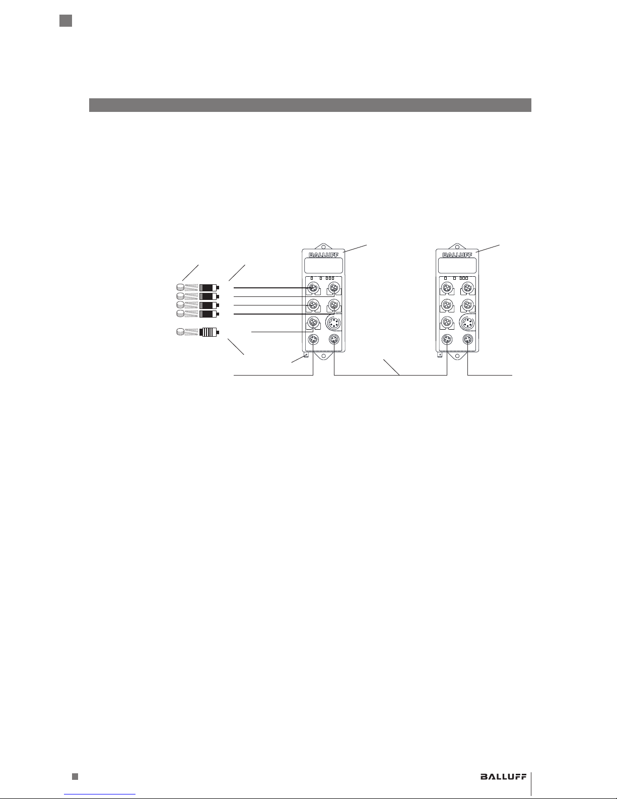
For BIS V-6108-048-C002, read/write heads in the BISVM-3 _ _, BISVL-3 _ _, and
BISVU-3 _ _ series can be connected to terminals H1...H4. BIS V-6108-048-C102 also
supports read/write heads in the BIS C-3 _ _ series (Adapter required).
Note
Read/write heads in the BISVU-3_ _ series are only supported with a device software
version of 3.0 or higher. Should the occasion arise, an update will be required.
Note
Device software as well as manuals with detailed information about the read/write
heads used are available at www.balluff.com.
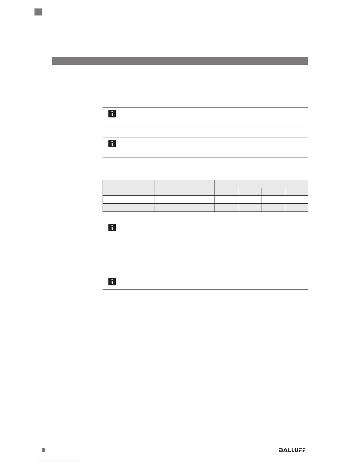
BISV processor units are available in different variants with respect to the supported read/write
heads. The following table shows the differences.
Processor Unit Available Connections Compatible Read/Write Heads
H1…H4 VM-3 _ _ VL-3 _ _ VU-3 _ _ C-3 _ _
BIS V-6108-048-C002 H1…H4 YES YES YES NO
BIS V-6108-048-C102 H1…H4 YES YES YES YES
Note
Only shielded cables are to be used for connecting read/write heads!
An adapter cable is required for connecting read/write heads in the BIS C-3_ _ series.
The maximum cable length for read/write heads in the BIS VM-3_ _, BISVL-3_ _,
and BISVU-3_ _ series is 50 m. For the BISC-3 _ _ series, the cable length is set at 1
m, 5 m, or 10 m plus the adapter depending on the design of the system.
Note
Visit www.balluff.com for more information on available software and accessories.
Open bus system for process and field communication in cell networks with few nodes and for
data communication in accordance with IEC61158/EN50173. Automation devices, such as
PLCs, PCs, operating and observation devices, sensors or actuators, can communicate using
this bus system. PROFINETIO is used in the BISV-6108.
3.5 Read/Write
Heads H1…H4
3.6 PROFINET

BIS V-6108 PROFINET
Processor Unit
10
english
IO-Link is defined as a standardized point-to-point connection between sensors/actuators and
an I/O module. An IO-Link sensor/actuator can send additional communication data
(e.g. diagnostics signals) in addition to the binary process signals over the IO-Link interface.
Compatibility with standard I/O:
– IO-Link sensors/actuators can be connected to existing I/O modules.
– Sensors/actuators that are not IO-Link-capable can be connected to an IO-Link module.
– Standard sensor/actuator cables can be used
Key technical data:
– Serial point-to-point connection
– Communication as an add-on to the standard I/O
– Standard I/O connection technology, unshielded, 20m cable length.
– Communication using 24 V pulse modulation, standard UART protocol
Process data (cyclical):
The GSDML file provides combined input/output modules (8 bytes…254 bytes) for mapping the
sensors:
– Combined input/output modules (8bytes…254bytes)
Service data (diagnostics, parameters):
– Parallel and non-reactive to process data
– Startup parameters can be configured using communication, then
– Binary switching signal
The device can be connected to a computer's USB port using the "Service/IO-Link" jack and
then behaves like a USB stick. This allows access to the internal memory, where the manual, the
GSDML file and a communications driver for service functions are saved. In addition, the BISV
has to be connected to a voltage source. The communication driver can be installed as needed,
but is not required for the USB port and BISV to function.
Note
Visit www.balluff.com for more information on available software and accessories.
3.7 IO-Link
3.8 Communication
Mode
Standard
I/O mode
3.9 USB Port
3Basic Knowledge

www.balluff.com
BIS V-6108 PROFINET
Processor Unit
11
english
Included in the scope of delivery:
– BISV-6108
– 5×closure cap
– Safety Precautions
Note
Visit www.balluff.com for more information on available software and accessories.
Figure 2: Mechanical connection
(dimensions in mm)
Figure 3:
A B
Installation examples (A: attachment to DIN rails, B: attachment to T-slotted framing)
1
2
DIN rail
Fastening
3
4
T-slotted framing
Holder for screw mounting
►Select a suitable installation position.
►Secure the processor unit using two M5 screws (strength category 8.8, lightly oiled,
tightening torque M = 5.5Nm).
4.1 Processor Unit
Scope of Delivery
4.2 Processor Unit
Installation
4 Installation

BIS V-6108 PROFINET
Processor Unit
12
english
Note
Make the ground connection either directly or using an RC combination to ground.
Connections
H 1
Port 1
Power
Port 2
H 2
H 4
H 3
Service /
IO-Link
FE
H1…H4 Read/Write Heads
Service/IO-Link USB function
Service/IO-Link
(master function)
Port 1 PROFINET IO port 1
Port 2 PROFINET IO port 2
FE Functional ground
Figure 4: Electrical Connections
H1…H4
M12 female, 5-pin, A-coded
Power
7/8" male, 5-pin
2
5
1
5
3
4
2
3 4
1
A
0V
B
H1...H4
VP
N.C.
PIN Function
1 +24V DC
2 A
3 0 V
4 B
5 n.c.
3
4
2
3
1
4
5
5
2
1
VP(Aktor)
VP(Sensor) BUS
FE
0V
0V
POWER
PIN Function
1 0 V
2 0 V
3 FE
4 +24V DC
5 Reserved, not
connected
IO-Link / Service
M12 female, 5-pin, A-coded
2
5
1
5
3
4
2
3
4
1
USB Tx
0V
Q/C (IO/Link)
IO-Link-Master
VP
USB Rx
IO-Link
PIN Function
1 VP (+24VDC)
2 n.c.
3 0 V
4 Q/C (IO-Link) or
digital input
5 n.c.
Service
PIN Function
1 n.c.
2 USB–
3 0 V
4 n.c.
5 USB+
PROFINET IO port 1/2
M12 female, 4-pin, D-coded
4
1
3
2
PIN Function
1 +Tx
2 +Rx
3 –Tx
4 –Rx
4.3 Electrical
Connections
4Installation

www.balluff.com
BIS V-6108 PROFINET
Processor Unit
13
english
Figure 5: Dimensions in mm
Housing material Zinc die-cast housing
H1…H4 VS24VDC - M12 female, 5-pin, A-coded
Service/IO-Link (master function) M12 female, 5-pin, A-coded
Power 7/8" male, 5-pin
PROFINET IO port 1 M12 female, 4-pin, D-coded
PROFINET IO port 2 M12 female, 4-pin, D-coded
Protection Class IP65 (with connectors)
Weight 800 g
Operating Voltage VS24 V DC ±20% LPS Class 2
Ripple ≤ 10%
Power Consumption ≤2 A
Application interfaces PROFINET IO, IO-Link
IO-Link port M12, A-coded, female
Pin 1 +24VDC, 1A
Pin 2 USB+
Pin 3 0 V
Pin 4 IO-Link / input max. 500mA
Pin 5 USB–
Dimensions
Mechanical Data
Electrical Data
Application
interfaces
5 Technical Data

BIS V-6108 PROFINET
Processor Unit
14
english
5Technical Data
Ambient Temperature 0°C…+60°C
Storage Temperature 0°C…+60°C
EMC (BIS V-6108-048-C002)
– EN 61000-6-2
– EN 61000-4-2/4/5/6 – Severity level 2B/3A/2A/3A
– EN 61000-4-3
80 MHz – 1000 MHz – Severity level 3A
1400 MHz – 2000 MHz – Severity level 3A
2000 MHz – 2700 MHz – Severity level 2A
– Emission as per EN 55016-2-3 – EN61000-6-3
EMC (BIS V-6108-048-C102)
– EN 61000-6-2
– EN 61000-4-2/4/5/6 – Severity level 2B/2A/1A/2A
– EN 61000-4-3
80 MHz – 1000 MHz – Severity level 3A
1400 MHz – 2000 MHz – Severity level 3A
2000 MHz – 2700 MHz – Severity level 2A
– Emission as per EN 301489-1/-3 – EN55022 (class A)
Vibration/shock EN 60068 Part 2-6/27
Operating
conditions

www.balluff.com
BIS V-6108 PROFINET
Processor Unit
15
english
The BISV-6108 processor unit and the controlling system communicate via PROFINET IO.
The system PROFINET IO consists of the following components:
– IO controller
– IO device (here, the BISV-6108 processor unit)
In a PROFINET network, IO controllers and IO devices can be connected to each other using all
common network topologies: a radial, linear, ring
or tree topology is possible.
Note
The BISV-6108 has a built-in IRT switch with 2ports for this purpose. This means
that both RT and IRT can be used.
In order to configure the parameters for the IO controller correctly based on type, the device
master data for the BIS V-6108 processor unit are included in the form of a GSD file. The data
can be found in the processor unit's internal memory and can be retrieved from there via the
USB port.
The data exchange takes place with the host control system in the input and output buffers
buffer. The size of these buffers must be configured by the master.
Note
The possible buffer sizes for each read/write head are stored in the GSDML file. A
minimum size of 8 and a maximum size of 254bytes can be configured; the value
must always be an even number. The maximum total buffer size of 1440bytes must
not be exceeded.
The processor unit and the host system communicate via the PROFINET protocol. This means
an IP address and a unique device name are required. The device name and the IP address can
be edited using the respective project planning software used, e.g. "Simatic Manager" and the IO
device.
Note
The BISV-6108 processor unit is shipped without a device name. The GSDML file
has the prepared device name "bisv6108048".
The device can be restored to factory condition using the display. Details for resetting and on
menu guidance of the display are described in Chapter “Display” on page 88.
PROFINETIO
Device master
data
Input/output
buffer
Device name and
IP address
Display setting/
menu navigation
6 Startup

BIS V-6108 PROFINET
Processor Unit
16
english
In project planning for PROFINET devices, a device is mapped as a modular system that
consists of a "BIS V-6108" header module and multiple data modules.
The device data required for project planning is stored in GSDML files (General Station
Description). The data modules of each read/write head, each IO-Link port and possible
additional modules are represented in the project planning software relative to their slot. The
GSDML file makes the possible data modules (inputs/outputs for the read/write heads and the
IO-Link port for various data widths) available. Appropriate data modules are assigned to a
specific slot for configuring the V-6108.
The "BIS V-6108" header module always has to be plugged in at slot0.
The data modules for the 4 read/write heads can be plugged in at slots 1 to 4. Depending on
use, an IO-Link port, a standard I/O, an IO-Link data module or an SIO module can be plugged
in at slot5.
Slot Module Function
0 BIS V-6108 header module Parameter configuration, no process data
1 Read/write head Parameter configuration and process data
2 Read/write head
3 Read/write head
4 Read/write head
5 IO-Link port pin4 IO-Link data modules of various data width or
configurable as a standard input port
6 Communication status Slots for optional additional modules
7 Sensor short circuit
8 Actuator overvoltage
9 Input pin 4
10 Output pin 4
11 Restart Pin4
6.1 Configuration
GSDML file
6Startup

www.balluff.com
BIS V-6108 PROFINET
Processor Unit
17
english
6Startup
Data modules for standard input ports:
Data module Data width
Standard I/O See “Auxiliary Modules” on page 18
Data modules for IO-Link_inputs
Data module Data width
IOL_I_1byte 1 byte
IOL_I_2byte 2 bytes
IOL_I_4byte 4 Byte
IOL_I_6byte 6 Byte
IOL_I_8byte 8 Byte
IOL_I_10byte 10 Byte
IOL_I_16byte 16 Byte
IOL_I_24byte 24 Byte
IOL_I_32byte 32 Byte
Data modules for IO-Link_outputs
Data module Data width
IOL_O_1byte 1 byte
IOL_O_2byte 2 bytes
IOL_O_4byte 4 Byte
IOL_O_6byte 6 Byte
IOL_O_8byte 8 Byte
IOL_O_10byte 10 Byte
IOL_O_16byte 16 Byte
IOL_O_24byte 24 Byte
IOL_O_32byte 32 Byte
Coding IO-Link
Data Modules

BIS V-6108 PROFINET
Processor Unit
18
english
Data modules for IO-Link_inputs_outputs
Data module Data width
Input Output
IOL_I/O_1/_1byte 1 byte 1 byte
IOL_I/O_2/_2byte 2 bytes 2 bytes
IOL_I/O_2/_4byte 2 bytes 4 Byte
IOL_I/O_4/_4byte 4 Byte 4 Byte
IOL_I/O_4/_2byte 4 Byte 2 bytes
IOL_I/O_2/_8byte 2 bytes 8 Byte
IOL_I/O_4/_8byte 4 Byte 8 Byte
IOL_I/O_8/_2byte 8 Byte 2 bytes
IOL_I/O_8/_4byte 8 Byte 4 Byte
IOL_I/O_8/_8byte 8 Byte 8 Byte
IOL_I/O_10/_10byte 10 Byte 10 Byte
IOL_I/O_4/_32byte 4 Byte 32 Byte
IOL_I/O_32/_4byte 32 Byte 4 Byte
IOL_I/O_16/_16byte 16 Byte 16 Byte
IOL_I/O_24/_24byte 24 Byte 24 Byte
IOL_I/O_32/_32byte 32 Byte 32 Byte
Note
Project planning software of various providers mostly offers graphical assistance
during configuration; the configuration string is automatically created.
Auxiliary Modules
Slot Subslot Input Output Contents
6 1 1 byte - Communication status
7 1 1 byte - Sensor short circuit
8 1 1 byte - Actuator overvoltage
9 1 1 byte - Input pin 4
Coding IO-Link
Data Modules
6Startup

www.balluff.com
BIS V-6108 PROFINET
Processor Unit
19
english
Slot 0, Subslot 1
Index Byte Bit Length Contents Values Default
1 0 0 1 Bit Global diagnosis 0/1 0
0 4 1 Bit HMI read only 0/1 0
0 5 1 Bit LEDs off 0/1 0
2 0 0 1 byte IO-Link port function 0/1/3/4/5/6 0
3 1 0 1 byte IO-Link safe state 0/1 0
Slot 1 to 4, subslot 1 in each case
Index Byte Bit Length Contents Values Default
1 0 0 1 Bit CRC 0/1 0
0 1 1 Bit Dynamic mode* 0/1 0
0 2 1 Bit Type serial number 0/1 0
0 3 1 Bit Slow tag detection* 0/1 0
0 4 1 Bit Low antenna
power*
0/1 0
0 5 1 Bit Head LEDs off 0/1 0
1 0 1 byte UID Compare
Count (only BIS
VL-3 _ _)
1…7 2
2 0 1 byte Tag type Data Carrier Type 1
0:
10:
11:
20:
21:
22:
30:
31:
All data carriers in the
series used
(e.g. BIS VM) are
recognized*
Mifare
ISO15693
EM4x02
Hitag1
HitagS
BIS C 32byte
BIS C 64byte
2 0 0 16 bits Process data length 8…254 Fixed
per
module
* Not for read/write heads BIS VU-_ _
6.2 Parameter
Configuration
Device Parameter
RFID port
parameter
6Startup

BIS V-6108 PROFINET
Processor Unit
20
english
Slot5, subslot 1
Index Byte Bit Length Contents Values Default
1 0 0 6 bits Cycle time 0…63 0
0 6 2 bits Cycle time base 0/1/2 0
2 0 0 1 byte Data window offset 0…31 0
1 0 1 byte Max. data input length 0…32 0
3 0 0 2 bits Validation type 0/1/2 0
1 0 1 byte Vendor ID Byte 0 0.255 0
2 0 1 byte Vendor ID Byte 1 0.255 0
3 0 1 byte Vendor ID Byte 2 0.255 0
4 0 1 byte Device ID Byte 0 0.255 0
5 0 1 byte Device ID Byte 1 0.255 0
6 0 16 bits Serial Number String Empty
string
4 0 0 1 Bit Parameter server upload 0/1 0
0 1 1 Bit Parameter server download 0/1 0
0 6 2 bits Parameter server enable 0/1/2 0
5 0 0 1 Bit Diagnosis enable 0/1 0
0 1 1 Bit Diagnosis low voltage sensor 0/1 0
0 2 1 Bit Diagnosis low voltage actuator 0/1 0
0 3 1 Bit Actuator/sensor short circuit 0/1 0
6 0 0 1 byte Process data length input 0…32 Fixed per
module
1 0 1 byte Process data length output 0…32 Fixed per
module
IO-Link port
parameter
6Startup
This manual suits for next models
2
Table of contents
Other Balluff Other manuals
Popular Other manuals by other brands

ReelCraft
ReelCraft 5600 ELS operating instructions

Sony
Sony HCD-BX20I - Compact Disc Receiver Component Service manual

Stivr
Stivr Pico G2 user manual

DP Dermaceuticals
DP Dermaceuticals DERMAPEN 3 user manual

Jetson
Jetson E-PUNK manual

Torklift
Torklift C4203 Important owner-operator installation instructions