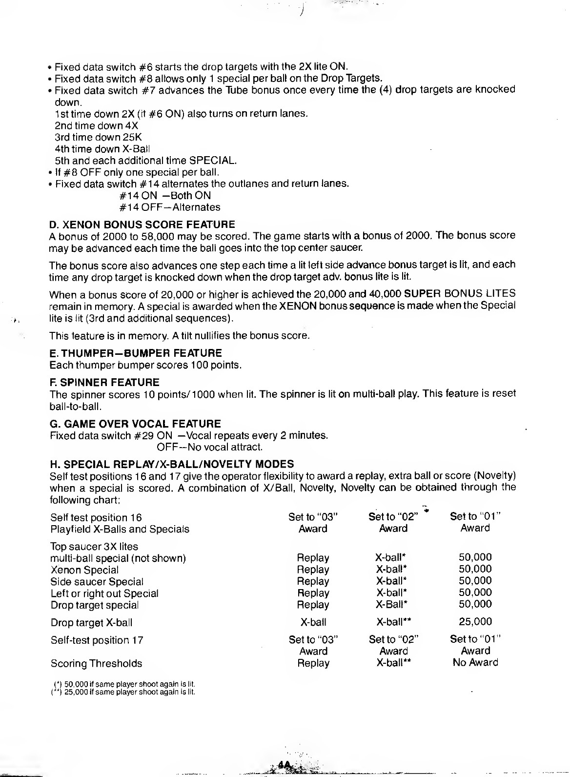
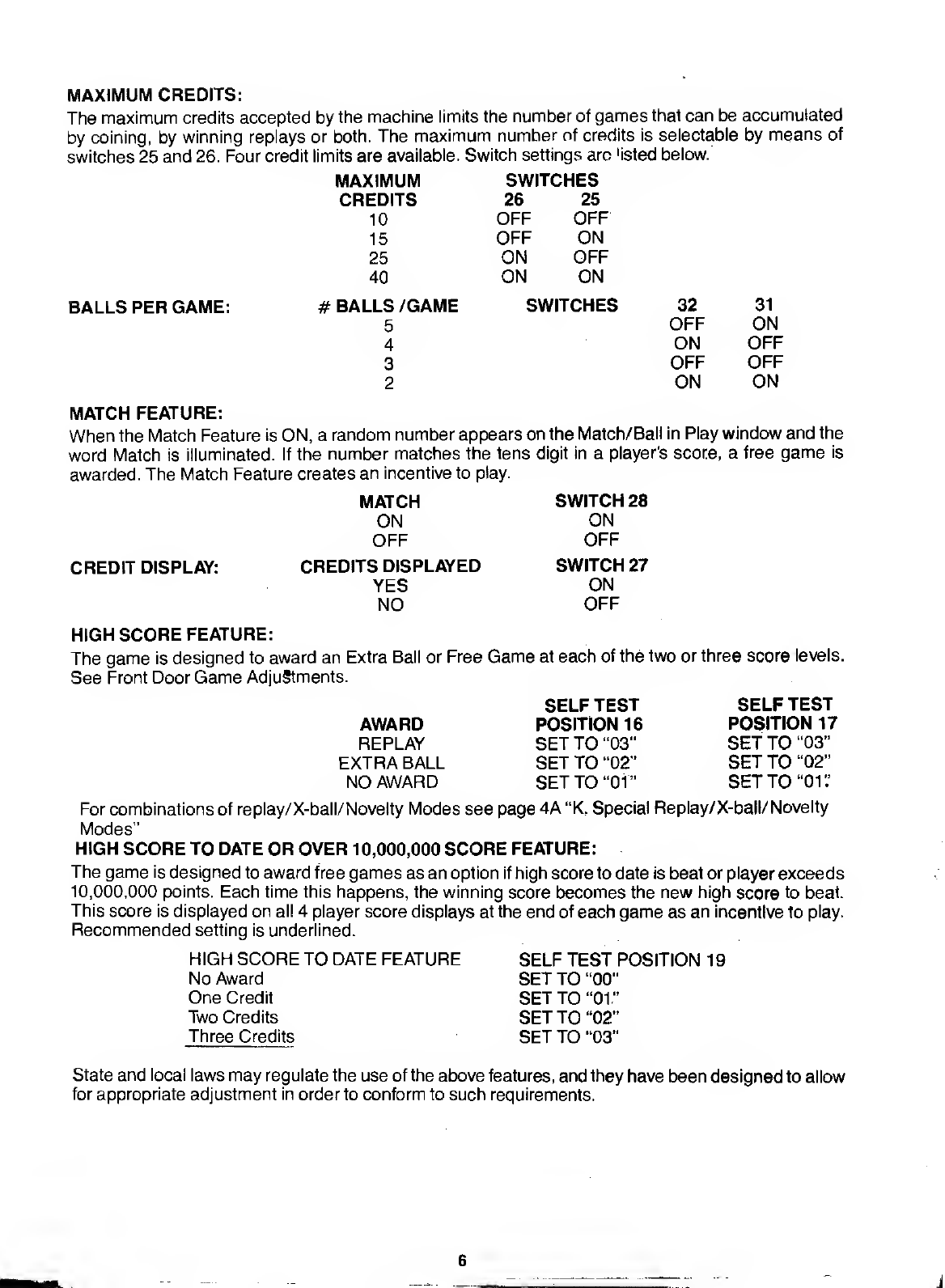
Bally Xenon User manual

GAME 1196
FO 680
PINBALL DIVISION
©BALLY MFG CORP. 1980
AtLftiGHTS RESERVED
90 deary DriveJBensenville, Illinois 60106, U.S.A.
Telephone: (312)860-6400 .
-... 'Vi *'-

Installation and General Game Operation Instructions
INDEX
PAGE
I. INSTALLATION 1
II. GENERAL GAME OPERATION 2
III. BOOKKEEPING FUNCTIONS 3
IV. FEATURE OPERATION AND SCORING 4
V. GAME ADJUSTMENTS .5
A. PLAYFIELD ADJUSTMENTS 5
B. BACKBOX ADJUSTMENTS 5
CREDITS/COIN 5
MAXIMUM CREDITS 6
BALLS/GAME ,6
MATCH FEATURE OPTION ... .'. 6
CREDIT DISPLAY ,6
HIGH SCORE FEATURE OPTION 6
HIGH SCORE TO DATE 6
GAME FEATURE OPTIONS 7
SOUND OPTION 7
C. FRONT DOOR GAME ADJUSTMENTS
HIGH SCORE FEATURE 8
HIGH SCORE TO DATE FEATURE 8
VI. RECOMMENDED SCORE CARDS 11
VII. RECOMMENDED SETTINGS 12
VIII. ROUTINE MAINTENANCE ON LOCATION 13
IX. TROUBLE SHOOTING ON LOCATION 13
X. SERVICE/PARTS 19
XI. PARTS LIST 20-35

BLOCK DIAGRAM-ELECTRONIC PINBALL GAME
'A 10:
VOCALIZER
DRIVER
MODULE
A2:
POWER
TRANSFORMER
MODULE
USED ONLY ON REQUIRED GAMES.

I- INSTALLATION
Assemble the game as follows:
Bolt legs to cabinet. Bolt back box to cabinet. Use flat washers under bolt heads. Gently feed
cable connectors and ground braid through cable port in back box. Screw ground braid to
braid in back box. Carefully and fully insert connectors on printed circuit assemblies.
On all games there are certain items that should be checked after shipment. These are visual
inspections which may avoid time consuming service work later. Minor troubles caused by
t^nZlT n^'? thif
J
ment are unavoidab,e-Cable connectors may be loosened, switches
(especially tilt sw.tches) may go out of adjustment. Plumb bob tilt switch should always be
adjusted after game is set on location and leg levelers are adjusted.
Visual inspections before plugging in line cord:
1
.
Check that all cable connectors are completely seated on printed circuit assemblies
2. Check that cables are clear of all moving parts.
3. Check for any wires that may have become disconnected.
4Check switches for loose solder or other foreign material that may have come loose in
shipment and could cause shorting of contacts.
5. Check wires on coils for proper soldering. Cold solder connections may not show up in
factory inspection, but vibration in shipment may break contact.
6. Check that fuses are firmly seated and making good contact.
7. Check the transformer for any foreign material shorting across wiring lugs.
8. Check wiring of transformer to correspond to location voltage. See figure 1
.
Check adjustment of the three (normally open) tilt switches:
1
.
Panel tilt on bottom of playfield panel. *
2. Plumb bob tilt on left side of cabinet near front door.
Lh^ft
b
K°V!plTbb°5tHt 'nSert the smal,erba,| (15/16"dia.)into the ball tilt assembly
and adjust the bracket so the ball will roll free to contact the switch blade, if front of cabinet is
raised.
TRANSFORMER CONNECTION INSTRUCTIONS
REFER TO POWER SUPPLY SCHEMATIC
IN GAME MANUAL FOR TABLE "A'
i»
115 VAC, 2-8.3-6. 7-10
120 VAC, 2-8,4-6. 7-11
220 VAC. 4-8,7-9
240 VAC, 4-8.7-11
PART OF POWER-TRANSFORMER MODULE A2, LOCATED IN LOWER CABINET
1/^-

II. GENERAL GAME OPERATION
Place ball into playfield by outhole.
Coin game. Coin should be rejected. Plug in line cord. Move power ON-OFF master switch at
bottom right front corner of cabinet to 'ON' position. The game will play apower-up tune to
announce game-readiness. Drop targets are reset, scores are set to zero, alternating with the
'High Score to Date,' and the game is ready for play. Coin game. The game should accept the
coin and post credits* for coins accepted (adjustable). Pressing the credit button on the door will
cause the outhole kicker to serve the ball to the shooter alley. The 1st player-up lite is lit. A
game-up tune* is played to announce play-readiness.
One player is posted each additional time the credit button is pressed (one to four can play) .The
credits are reduced by one each time the credit button is pressed until the credits are reduced to
zero.
Shooting the ball initiates play.
The game awards all points earned by the player. If spinner is turning and scoring when the ball
hits atarget, the spinner and the target scores are awarded.
When the ball enters the outhole, the bonus score is added to the total score. The player-up
and/or ball in play on the back box is advanced one position. The outhole kicker serves the ball
to the shooter alley and play is resumed. This continues until each player has played the
allowable number of balls per game (adjustable). At this time the 'Game Over' light is lit. A
random Match* number appears and the 'Match' light is lit. If the number is the same as the last
two digits in aplayer's score, afree game is awarded.
Extra balls won during the course of the game are played immediately after the player's regular
ball enters the outhole. The player-up and/or ball in play an the back box are not advanced for
extra ball play. Bonus score is added to the player's score before the game serves the extra ball
for play.
Scoring over 10,000,000 gives "High Score to Date" award.
At the end of the game, a'High Score to Date' is alternately flashed with all 4player scores. If the
'High Score to Date' is beat, this feature* awards free games.
Tilting the game results in loss of aball. The flippers, thumper-bumpers, etc., go 'dead.' Bonus
points are not scored. The purpose of the tilt penalty is to discourage the player from jostling the
machine in an attempt to prolong play. Game action becomes normal after the ball kicker
assembly serves the ball to the shooter alley.
Slamming the machine results in loss of the game. AH feature lights go out, the game goes
'dead,' and atime delay occurs. The purpose of the time delay is to discourage unnecessary
abuse of the machine. After the delay, the 'Game Over' light lites and the power-up tune is
played. The time delay occurs anytime one of the slam switches is made to contact. There are
two factory installed slam switches, on the front door, and one on left side of cabinet. (Any
number of slam switches could be installed by the operator, to meet his individual requirement.)
The switch should be adjusted to have approximately 1/16" gap between the contacts. The
weighted blade should be adjusted to attain the desired sensitivity. Decreasing the gap
between contacts will make the switch more sensitive. Opening the gap will reduce sensitivity.
'Some tunes and features can be disabled by operator if so desired. See Back Box Adjustments.
NOTE: Scoring and feature units will differ from game to game.

III. BOOKKEEPING FUNCTIONS
The game is designed to help the operator perform certain accounting functions. The game can
display the number of total plays and replays (free games). It can display the number of coins
dropped down each coin chute. The bookkeeping functions are displayed on all player score
displays simultaneously. An identification number, 05 to 15, appears on the Match/Ball in Play
window as follows:
05— 00 to— 40 =Current Credits
*06—100000 to—99999= Total Plays (Payed &Free Games)
*07— 10000 to—99999 -Total Replays (Free Games)
08— 00 to—99999 =Game Percentage
09— 00 to—99999 -Total times 'High Score to Date' is beat
*10— 10000 to—99999 -Coins Dropped thru Coin Chute #1
*1 1—10000 to—99999 -Coins Dropped thru Coin Chute #2**
*1 2— 10000 to—99999 =Coins Dropped thru Coin Chute #3**
*1 3—00 to—99999 =Number of Specials awarded from Panel Specials Only
*1 4—00 to—99999 =Number of minutes of Game Play
*1 5_ 00 to—99999 -Number of Service Credits
The game displays the first bookkeeping entry if the Self-Test button (See Fig. Ill) on the inside
of the front door is pressed ten times. Alternately push and release the Self-Test button at one
second intervals. The number 05 appears in the 'Match/Ball in Play' window. Current credits
appear on the playe'r score displays. Each additional press of the button causes the next entry
to be displayed.
After the data in each bookkeeping register is recorded, it can be set to zero simply by pressing
switch button S33, located on A4, the MPU module inlhe back box (See Fig. Ill), or by pressing
the Coin Chute #3 switch. Any or all registers can be cleared by alternating between the
Self-Test button and the switch button S33 on the MPU module or Coin Chute #3 switch. The
operator is given this option as a possible convenience and can elect to use or not use it as his
needs direct.
Pressing the button 5more times causes the game to play the power-up tune and light the
Game Over light.
Service credits are designed to allow the serviceman to test the game under actual play
conditions without disturbing the bookkeeping records that reside at identification numbers 06,
07,10,11 and 12.
To obtain Service Credits, push and release the Self-Test switch until identification number 05
appears in the 'Match/Ball in Play' window. Hold in the Credit button until the desired number of
Service Credits (up to five) appears on the player score displays.
NOTE: If, upon accessing identification number 05, anumber of credits greater than five is
displayed, pressing the credit button has no effect.
Identification number 15is reserved as a record of the number of Service Credits used.
The 10,000 level is pre-set at the factory; can be set io zero, initially, if desired.
"If Coin Chute is not used in game, number displayed (if other than 00) on Player Score displays has no significance.
NOTE: If "Total Play" register is reset to zeroes then "Total Replays" register should also be reset to zeroes to maintain the
game percentage value.

#1196 XENON
FEATURE OPERATION &SCORING
A. THE TUBE FEATURE .,*=. ^u4.uMfn.t
Each time aball is shot into the TUBE, itfalls itethe Exit Chamber Saucer. Each time aball falls into
the Exit Chamber Saucer, it scores the lit Exit value bonus score, advances the Exit value and is kicked
back onto the playing surface (see Bbelow). The background sound and accompanmg lighting effects
increase in tempo in proportion to the scoring on the playfied; these are reset to the starting tempo
each time the ball enters the Exit Chamber Saucer. This feature is held in memory from bail-to-ball on
Switch #22.
•Fixed data switch #22 allows the TUBE bonus to be retained in memory:
#22 ON -Tube bonus recalled.
#22 OFF-Tube bonus reset.
•Fixed data switch #24 sets the top limit of the TUBE bonus.
#24 ON —90,000 Exit value bonus limit
#24 OFF-50,000 Exit value bonus limit
•Fixed data switch #21 controls the TUBE special lite once the exit value bonus limit is reached.
#21 ON -Special alternates once made
#21 OFF-Only ONE SPECIAL is possible, bonus resets after special is made.
•Fixed data switch #23 controls the advances of the TUBE bonus every time the ball falls into the Exit
Chamber Saucer.
#23 ON -2 advances on the Exit value bonus score.
#23 OFF-1 advance on the Exit value bonus score.
B.TOP HOLE FEATURE _+,
Each time the ball goes into the top hole the outhole XENON bonus may be advanced by one or two
letters and one Xsymbol is awarded in the center of the playfield.
The first time (3) Xsymbols are completed, the tube entrance lite is lit to capture aball in the Exit
Chamber Saucer. The 2nd time the 3X symbol sequence is completed, the captured ball, along with
the player's ball, is released. The next time the sequence is completed, during multi-ball play, the
outlane special lites are lit. The next time asequence is completed, aspecial is awarded (note: only
during multi-ball play). If one ball enters the outhole before the sequence is completed the Tube is
thenrequalified.
•Fixed data switches #15, 16 &30 control the top saucer, (see next page).
•Fixed data switches #15 &16 control the outhole XENON bonus advances awarded in the top
saucer: 15 OFF 16 OFF- 5K &No. Adv. »
15 ON 16 OFF-1 OK &1 Adv.
15 ON 16 ON -10K &2Adv.
•Fixed data switch #30 controls the Tube captured ball iites:
#30 ON -qualifying iites in memory.
#30 OFF-Not in memory.
C. DROP TARGET &TOP BUTTON FEATURE
Each time the ball rolls over alit top button, 500 points are scored and the corresponding numbered
drop target is knocked down. There are (2) sets of drop targets lites: One lite by each top numbered
button and one lite behind each drop target. When any target is knocked down, both its corresponding
lites go out.
When all (4) drop targets are knocked down, 10,000 pts. are scored and the lit feature is awarded.
These features are reset ball-to-ball.

•Fixed data switch #6 starts the drop targets with the 2X lite ON.
•Fixed data switch #8 allows only 1special per ball on the Drop Targets.
•Fixed data switch #7 advances the Tube bonus once every time the (4) drop targets are knocked
down.
1st time down 2X (if #6 ON) also turns on return lanes.
2nd time down 4X
3rd time down25K
4th time down X-Ball
5th and each additional time SPECIAL.
•If #8 OFF only one special per ball.
•Fixed data switch #14 alternates the outlanes and return lanes.
#14 ON -Both ON
#14 0FF-Alternates
D. XENON BONUS SCORE FEATURE
Abonus of 2000 to 58,000 may be scored. The game starts with abonus of 2000. The bonus score
may be advanced each time the ball goes into the top center saucer.
The bonus score also advances one step each time alit left side advance bonus target is lit, and each
time any drop target is knocked down when the drop target adv. bonus lite is lit.
When abonus score of 20,000 or higher is achieved the 20,000 and 40,000 SUPER BONUS LITES
remain in memory. Aspecial is awarded when the XENON bonus sequence is made when the Special
lite is lit (3rd and additional sequences).
This feature is in memory. Atilt nullifies the bonus score.
E. THUMPER-BUMPER FEATURE
Each thumper bumper scores 100 points.
F. SPINNER FEATURE
The spinner scores 1points/ 1000 when lit. The spinner is lit on multi-ball play. This feature is reset
ball-to-ball.
G. GAME OVER VOCAL FEATURE
Fixed data switch #29 ON —Vocal repeats every 2minutes.
OFF—No vocal attract.
H. SPECIAL REPLAY/X-BALL/NOVELTY MODES
Self test positions 16and 17give the operator flexibility to award areplay, extra ball or score (Novelty)
when aspecial is scored. Acombination of X/Bafl, Novelty, Novelty can be obtained through the
following chart;
Set to "03" Set to "02" *Set to "01"
Self test position 16
Playfield X-Balls and Specials
Top saucer 3X lites
multi-ball special (not shown)
Xenon Special
Side saucer Special
Left or right out Special
Drop target special
Drop target X-ball
Self-test position 1
7
Scoring Thresholds
(*) 50,000 if same player shoot again is lit.
(**) 25,000 if same player shoot again is lit.
Award Award Award
Replay X-ball* 50,000
Replay X-Ball* 50,000
X-ball X-ball** 25,000
Set to "03" Set to "02" Set to "01
'
Award Award Award
Replay X-ball** No Award
._ %*kMb W^

V. GAME ADJUSTMENTS
A. Playfield Panel Post Adjustments:
Posts that control left and right outlane opening on panel can be removed to make access
to outlanes easier or harder for ball to enter. See Figure II.
Easier entry will decrease playing time and scoring (conservative).
Harder entry will increase playing time and scoring (liberal).
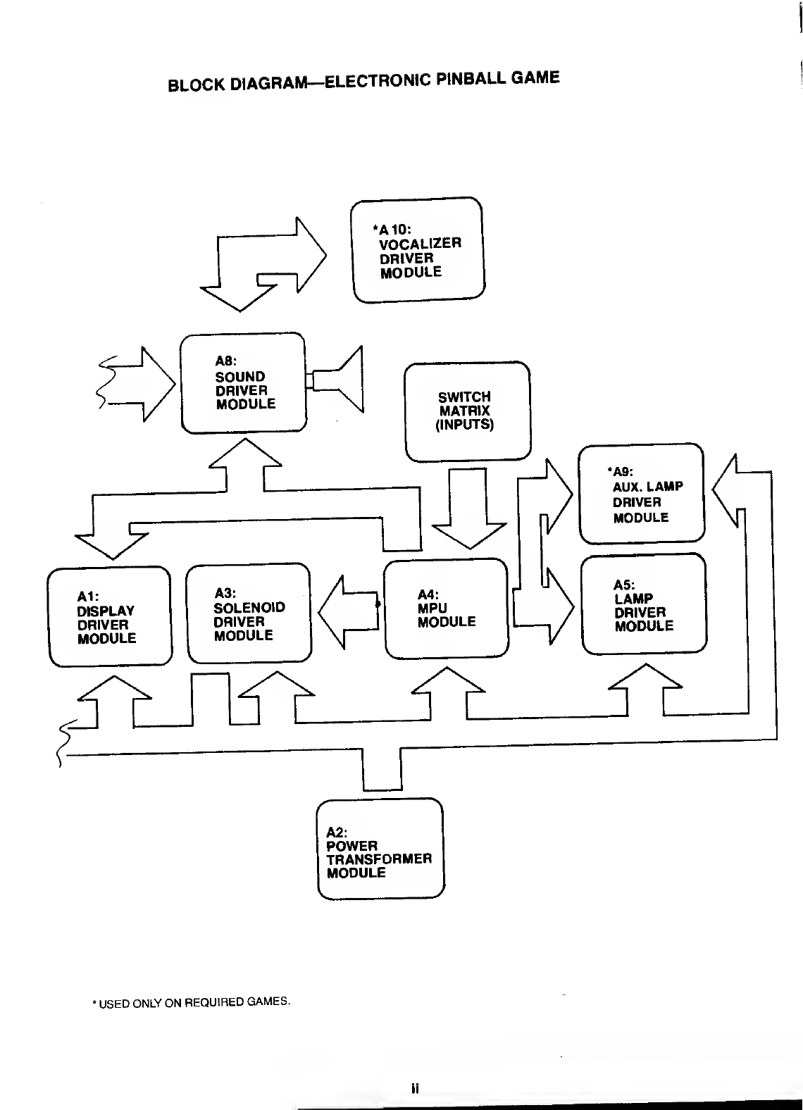
B. Back Box Game Adjustments:
Each game has thirty-two switches located on A4, the MPU module, located in the back
box, that allow play to be customized to the location. See Figure III. Credits per coin,
maximum credits, credit display, balls per game, match feature, high game feature,
special award and melody are selectable by means of the switches. The switches are
contained in four-sixteen lead packages numbered S1-8, S9-16, S17-24, and S25-32 for
easy identification. The "ON" toggle position is marked on the assembly. Turn off power
before making adjustments.
Credits/Coin Adjustments:
The credits per coin are selectable by means of S17-S20 for coin chute #2 (Center). The
switch settings and resultant credits/coin are as follows:
S20 S19 S18 S17 Credits/Coin S20 S19 S18 S17 Credits/Coin
OFF OFF OFF OFF Same as Coin Chute #1 Settings ON OFF OFF OFF 8/1 Coin
OFF OFF OFF ON 1/1 Coin ON OFF OFF ON 9/1 Coin
OFF OFF ON OFF 2/1 Coin ON OFF ON OFF 10/1 Coin
OFF OFF ON ON 3/1 Coin ON OFF ON ON 11/1 Coin
OFF ON OFF OFF 4/1 Coin ON ON OFF OFF 12/1 Coin
OFF ON OFF ON 5/1 Coin ON ON OFF ON 13/1 Coin
OFF ON ON OFF 6/1 Coin ON ON ON OFF 14/1 Coin
OFF ON ON ON 7/1 Coin *ON ON ON ON 15/1 Coin
The credits given are selectable by means of switches 1-5 incl., for coin chute #1 and
switches 9-13 incl., for coin chute #3. Thirty-one different credit ratios are available for
each coin chute. The switch settings and resultant credits/coin are listed below.
CREDITS/COIN ADJUSTMENTS TOTAL
COIN CHUTE SWITCHES CREDITS CREDITS CREDITS CREDITS CREDITS/COINS
#1 (HINGE SIDE) 5 4 3 2 1
OR #3 13 12 11 10 9
(RIGHT SIDE) OFF OFF OFF OFF OFF 1/1 Coin
OFF OFF OFF OFF ON 2/1 Coin
OFF OFF OFF ON OFF 3/1 Coin
OFF OFF OFF ON ON 4/1 Coin
OFF OFF ON OFF OFF 5/1 Coin
OFF OFF ON OFF ON 6/1 Coin
OFF OFF ON ON OFF 7/1 Coin
OFF OFF ON ON ON 8/1 Coin
OFF ON OFF OFF OFF 9/1 Coin
OFF ON OFF OFF ON 12/1 Coin
OFF ON OFF ON OFF 14/1 Coin
OFF ON OFF ON ON 1/2 Coins*
OFF ON ON OFF OFF 2/2 Coins*
OFF ON ON OFF ON 3/2 Coins*
OFF ON ON ON OFF 4/2 Coins*
OFF ON ON ON ON 5/2 Coins*
ON OFF OFF OFF OFF 6/2 Coins*
ON OFF OFF OFF ON 7/2 Coins*
ON OFF OFF ON OFF 8/2 Coins*
ON OFF OFF ON ON 9/2 Coins*
ON OFF ON OFF OFF 12/2 Coins*
ON OFF ON OFF ON 14/2 Coins*
ON OFF ON ON OFF 1/1st Coin 2/2nd Coin 3/2
ON OFF ON ON ON 0/1 st Coin* 1/ 2nd Coin 1/3rd Coin 1/4th Coin 3/4
ON ON OFF OFF OFF 0/1 st Coin* 1/2nd Coin 0/3rd Coin** 2/4th Coin 3/4
ON ON OFF OFF ON 1/1 st Coin 1/2nd Coin 1/3rd Coin 2/4th Coin 5/4
ON ON OFF ON OFF 1/1st Coin 2/2nd Coin 1/3rd Coin 3/4th Coin 7/4
ON ON OFF ON ON 1/1st Coin 2/2nd Coin 2/3rd Coin 2/4th Coin 7/4
ON ON ON OFF OFF 1/1 Coin
ON ON ON OFF ON 1/1 Coin
ON ON ON ON OFF 1/1 Coin
ON ON ON ON ON 1/1 Coin
*No Credits until second coin sdropped.
"No Credits until 4th coin is dropped.

MAXIMUM CREDITS:
The maximum credits accepted by the machine limits the number of games that can be accumulated
by coining, by winning replays or both. The maximum number of credits is selectable by means of
switches 25 and 26. Four credit limits are available. Switch settings arc 'isted below.
MAXIMUM SWITCHES
BALLS PER GAME:
CREDITS 26 25
10 OFF OFF
15 OFF ON
25 ON OFF
40 ON ON
#BALLS /GAME SWITCHES 32 31
5OFF ON
4ON OFF
3OFF OFF
2ON ON
MATCH FEATURE:
When the Match Feature is ON, arandom number appears on the Match/Ball in Play window and the
word Match is illuminated. If the number matches the tens digit in aplayer's score, afree game is
awarded. The Match Feature creates an incentive to play.
CREDIT DISPLAY:
MATCH
ON
OFF
CREDITS DISPLAYED
YES
NO
SWITCH 28
ON
OFF
SWITCH 27
ON
OFF
HIGH SCORE FEATURE:
The game is designed to award an Extra Ball or Free Game at each of the two or three score levels.
See Front Door Game Adjustments.
AWARD
REPLAY
EXTRA BALL
NO AWARD
SELF TEST
POSITION 16
SET TO "03"
SET TO "02"
SET TO "01"
SELF TEST
POSITION 17
SET TO "03"
SET TO "02"
SET TO "01 '.'
For combinations of replay/X-ball/Novelty Modes see page 4A "K, Special Replay/X-ball/ Novelty
Modes"
HIGH SCORE TO DATE OR OVER 10,000,000 SCORE FEATURE:
The game is designed to award free games as an option if high score to date is beat or player exceeds
10,000,000 points. Each time this happens, the winning score becomes the new high score to beat.
This score is displayed on all 4player score displays at the end of each game as an incentive to play.
Recommended setting is underlined.
HIGH SCORE TO DATE FEATURE
No Award
One Credit
Two Credits
Three Credits
SELF TEST POSITION 19
SET TO "00"
SET TO "01"
SET TO "02"
SET TO "03"
State and local laws may regulate the use of the above features, and they have been designed to allow
for appropriate adjustment in orderto conform to such requirements.

#1196 XENON
SOUND OPTION
The game is designed to make several tones and noises to announce power-up, game-up, etc. The
tones are intended to attract attention to the game and increase game usage. The tones are controlled
by pressing self test button until the #18 shows on the match/ball in play display. Now pulse replay
button to desired sound setting.
Setting "00"
Most switches associated chimes without feature background.
Setting "01"
Playfield switches associated chimes with background.
Setting "02"
Most scoring will have noise effect without background.
Setting "03"
Most alt scoring will have anoise effect with background.
GAME FEATURE OPTIONS:
Drop target 2X lite adjustment:
Liberal SW. 6ON
Conservative SW. 6OFF
Drop target tube exit value adjustment:
Liberal SW. 7ON
Conservative SW. 7OFF
Drop target special lite adjustment:
Liberal SW 8ON
Conservative SW. 8OFF
2X is on at start of game.
2X is not on at start of game.
Making 4drop targets, exit value steps up 1.
Making 4drop targets, exit value does not step.
Making 4drop targets, lite stays lit.
Making 4drop targets, lite steps to 25,000.
Outlanes &Flipper feed lanes arrow lite adjustment:
Liberal SW 14 ON Both lites come on for outlane or flip feed.
Conservative SW 14 OFF 1lite comes on for either one then alternates.
Top saucer scoring and Xenon lite advances adjustment:
Liberal SW. 15, 16 ON Scores 10,000 and 2lite advances.
Medium SW 15 ON, 16 OFF Scores 10,000 and 1lite advance.
Conservative SW. 15,16 OFF Scores 5,000 and no lite advances.
Side saucer mota special lite adjustment:
Liberal SW. 21 ON
Conservative SW. 21 OFF
Side saucer mota score lites adjustment:
Liberal SW. 22 ON
Conservative SW. 22 OFF
Side saucer mota lite advance adjustment:
Liberal
Conservative SW. 23 ON
SW 23 OFF
Special will alternate.
Special resets with the score.
Any lite lit will come on for next ball.
Any lite will reset to 5,000.
Mota lites advance 2times.
Mota lites advance 1at atime.
Side saucer mota 50,000, 90,000 lite adjustment:
Liberal SW. 23 ON Mota lites advance 2times.
Conservative SW 23 OFF Mota lites advance 1at atime.
Side saucer mota 50,000, 90,000 lite adjustment:
Liberal SW. 24 ON Lites step to 90,000.
Conservative SW. 24 OFF Lites step to 50,000 only.
Game over attract adjustment:
Liberal SW 29 ON
Conservative SW. 29 OFF
Top saucer first 2X lites adjustment:
Liberal SW. 30 ON
Conservative SW. 30 OFF
Voice says "Try Me Again."
No Voice.
Any lites on will come on for next ball,
if the tube entrance light is not flashing.
Any lites on will not come on for next ball.

C. FRONT DOOR GAME ADJUSTMENTS
High Score Feature Adjustments:
The game is designed to award an extra ball (option) or afree game at each of three score
levels. The recommended levels are on the score card in the game.
Any level from 10,000 to 9,999,000 can be set, as desired. It is also possible to reset or turn off
(00) any or all of the levels, if desired.
1
.
Push and release Self-Test button (See Figure III) at one second intervals approximately
six times or until identification number 01 appears on the 'Match/Ball in Play1display.
2. The number on the Player Score Displays is the score level.* It can be increased, if
desired, by holding the credit button in. To decrease the score level, hold the credit button in
and depress and release the Self-Test button. Release the credit button when the desired
number appears. Note that the level changes 10,000 points at atime. If the number '00' is
left on the displays, the high score feature is eliminated for that level.
3. Repeat steps 1and 2for the second and third score levels. The identification numbers
'02' and '03' on the Match/Ball in Play display are for the second and third levels,
respectively.
High Score to Date and 10,000,000 Feature:
The game is designed to award free games when 'High Score to Date' is beat, or if the player
exceeds 10,000,000 points.
It is recommended that the level, which will build with play, be periodically reset to the factory
recommended level to encourage game play. The adjustment procedure is the same as for the
High Score Feature Adjustment, Steps 1and 2. Continue pushing the Self-Test button until the
identification number '04' appears on the 'Match/Ball in Play' display and then do Step 2.
Any level from '00' to 9,990,000 can be set as described. It is to be noted that '00' does NOT turn
off the feature, as it does on High Score feature. The feature is turned off by self test position 19 as
discussed under 'Back Box Game Admustments.'
SELF TEST SETUP FOR 16-19:
To set up positions 16-19 push and release self test button till 16 shows on match/ball in play. Now
pulse replay button for recommended setup from "00" thru "03!' Repeat for positions 17, 18 or 19.
SOUND
In addition to individual volume controls for speech and other game sounds on the Sounds Plus
Board. There is also aMaster Volume Control located on the front door, (refer to page 10)
Please note that these module volume controls should be adjusted prior to setting the control on
the front door.
*Can be quickly set to '00' by pressing S33 on the MPU assembly in the back box or Coin Chute switch #3. {See Figure III).

#1196 XENON
RUBBER PARTS
A. R-521-2 1WDIA. (3)
B. R-521-6 3V2" DIA.
C. R-521-1 1"DIA.
D. R-521 %" DIA. (2)
E. R-521-3 2" DIA.
F. R-521 -4 21
/2" DIA. (4)
G. R-406-3 FLIPPER (2)
PANEL TOP PARTS
1. Arch Rail M-1774
2. Rail Post C-907 (2)
3. Rail Post Cap C-908 (2)
4. Bottom Arch P-5871-81
5. Shooter Gauge P-6359-46
6. Ball Gate (Left) A-1475-12
7. Ball Gate (Right) A-1475-13
8. Panel Plastics M-1 330-1 72
9. Thumper Bumper Cap A-3713-66 (4)
10. Rollover Button C-587-6
11. Rollover Wire Assy. AS-2806 (3)
12. Rollover Wire Assy. AS-2806-1 (4)
13. Xenon Light Strip AS-2518-60
14. Ball Tube M-1 922
15. Soinner Gate Assy. AS-2250-78
17. Ball Ramp Assy. A-3066-51
19. Micro Sw. &Wire AS-2744-14
20. Ball Guide Assy. A-3032-57
21. Ball Guide Assy. A-3032-58
22. Ball Down Ramp P-6244-107
23. Ball Guide Stop Assy A-2898-37
24. Ball Gate &Wire Assy. AS-2250-24
25. Target Assy. (Yellow) AS-2911-21 (2)
26. Drop Target Assy. AS-3038-2
27. Ball Guide Wire M-121-18 (2)
28. Ball Guide Wire M-1 21 -43
29. Ball Guide Wire M-1 21 -44
30. Flipper &Shaft Assy. AS-2214-21 (2)
31. Buffer Wire M-1 21 -53 (2)
32. Minipost &Rubber Assy. AS-2836-1 (5)
33. Ball Guide Wire M-121-108
34. Ball Guide Assy. A-3032-59
35. Ball Guide Assy. A-3032-60

«— 1ST PLAYER
Al DISPLAY
DRIVER ASSYS.
2ND PLAYER
CREDITS
MATCH /BALL -
IN PLAY
4TH PLAYER
3RD PLAYER
self test
button
CREDIT
BUTTON
REMOTE VOLUME
CONTROL
.
FRONT DOOR
SLAM
SWITCH
PLUMB BOB TILT /
INCLINED TILT '
Transformer Assy. i
BACK BOX
VOLTAGE REGULATOR
SOLENOID DRIVER ASSY.
SOUND ASSY.
LAMP DRIVER ASSY.
=-I VnC&LIZER ASSY
CABINET
LEG LEVELING ADJUSTMENT,
TYPICAL
DETAIL: 3I-S32
MPU ASSY.
FIGURE HI. ELECTRONIC PIN BALL MACHINE
-10-

RECOMMENDED
instruct. Score Cards^and High Score Feature Settings
to be used on XENON nw
3-BALL
REPLAYS
instruction Card
Score Card
1Replay at 500,000
1Replay at 1,000,000
5-BALL
M-1508-93-E
M-1508-93-B
REPLAYS
Instruction Card
Score Card
1Replay at 600,000
1Replay at 1,100,000
EXTRA BALL
Instruction Card
Score Card
1Extra Ball at 600,000
1Extra Ball at 900,000
1Extra Ball at 1,200,000
M-1 508-93-E
M-1508-93-A
M-1508-93-F
M-1508-93-AW/NN-1
REPLAYS
M-1508-H-1
M-1 508-1-1
M-1508-J-1
M-1508-K-1
M-1508-L-1
M-1508-M-1
M-1508-N-1
M-1508-O-1
M-1508-P-1
M-1508-Q-1
M-1508-R-1
M-1508-S-1
M-1508-T-1
M-1508-U-1
M-1508-V-1
M-1508-FF-1
M-1508-GG-1
M-1508-HH-1
M-1 508-11-1
M-1508-JJ-1
M-1508-KK-1
400,000
450,000
500,000
500,000
550,000
600,000
650,000
700,000
800,000
800,000
900,000
900,000
1,000,000
1,100,000
1,200,000
500,000
600,000
700,000
800,000
900,000
1,000,000
ADDITIONAL CARDS
950,000
1,000,000
1,000,000
1,100,000
1,100,000
1,100,000
1,200,000
1,200,000
1,300,000
1,400,000
1,400,000
1,500,000
1,500,000
1,600,000
1,600,000
800,000
1,100,000
1,400,000
1,300,000
1,400,000
1,500,000
1,100,000
1,300,000
1,600,000
1,600,000
1,600,000
1,800,000
EXTRA BALL
M-1508-NN-1 600,000
M-1 508-OO-1800,000
M-1508-PP-1 900,000
M-1508-QQ-1 1,000,000
900,000
1,100,000
1,200,000
1,400,000
1,200,000
1,400,000
1,400,000
1,800,000
Instruction Card, Novelty
M-1508-93-G
H^gamelo date recommended levels;
(reset periodically)
3BALL 1,200,000
5BALL 1,300,000
11

#1196 XENON
RECOMMENDED SETTINGS
RECOMMENDED REPLAY GAME SETTINGS FOR: 3-BALL 5-BALL
DROP TARGET 2X LITE SW. 6ON OFF
DROP TARGET SIDE SAUCER LITE ADVANCE SW. 7OFF OFF
DROP TARGET 25K AND SPECIAL LITE SW 8OFF OFF
OUTLANE AND FLIP FEED ARROW LITES SW. 14 ON OFF
TOP SAUCER SCORING &XENON LITE ADVANCE SW15 ON ON
TOP SAUCER SCORING &XENON LITE ADVANCE SW16 ON OFF
SIDE SAUCER SPECIAL LITE SW.21 ON OFF
SIDE SAUCER SCORE LITES RECALL SW. 22 ON ON
SIDE SAUCER LITE ADVANCE SW 23 ON OFF
SIDE SAUCER 50K or 90K SW. 24 ON ON
GAME OVER VOICE SW. 29 ON ON
TOP SAUCER 2XLITES RECALL SW. 30 ON OFF
BALLS PER GAME SW 31 OFF ON
BALLS PER GAME SW. 32 OFF OFF
REPLAY 3-BALL 5-BALL
Instruction Card M-1508-93-E M-1508-93-E
Score Card M-1508-93-B M-1508-93-A
Major Mode Self Test Position 16, 17 Self Test Position 16, 17
Set to "03" Set to "03"
Match SW. 28 ON SW.28 0N
High Score to Date Self Test Position 1
9
Self Test Position 1
9
Set to "03" Set to "03"
X-BALL
Instruction Card M-1508-93-F
Score Card M-1508-93-AW/NN-1
Major Mode Self Test Position 16, 1
7
Set to "02"
Match SW. 28 OFF
High Score to Date Self Test Position 1
9
Set to "00"
NOVELTY
Instruction Card M-1508-93-G M-1508-93-G
Major Mode Self Test Position 16, 17 Self Test Position 16, 17
Set to "01" Set to "01"
Match SW. 28 OFF SW.28 0FF
High Score to Date Self Test Position 19 Self Test Position 1
9
Set to "00" Set to "00"
ADDITIONAL CARDS FOR PAGE 11
REPLAYS
M-1508-UU 480,000 720,000 M-1508-EEE 380,000 670,000 820,000
M-1508-VV 500,000 740,000 M-1508-FFF 400,000 690,000 840,000
M-1508-WW 520,000 760,000 M-1508-GGG 420,000 710,000 860,000
M-1508-XX 540,000 780,000 M-1508-HHH 440,000 730,000 880,000
M-1508-YY 560,000 800,000 M-1508-III 460,000 750,000 900,000
M-1508-ZZ 580,000 820,000 M-1508-JJJ 480,000 770,000 920,000
M-1508-AAA 600,000 840,000 M-1508-KKK 500,000 790,000 940,000
M-1508-BBB 620,000 860,000 M-1508-LLL 520,000 810,000 960,000
M-1508-CCC 640,000 880,000 M-1508-MMM 540,000 830,000 980,000
M-1508-DDD 660,000 900,000 M-1508-NNN
12
560,000 850,000 990,000

VIII. ROUTINE MAINTENANCE ON LOCATION:
Self-Test routines are written into the game design. They are particularly useful for routine
maintenance. The tests are described below. The first test is automatic and occurs on
power-up. This test causes the MPU module A4 to examine itself for failures. Seven flashes of
an LED indicates proper operation. The second series of self-diagnostic tests causes the MPU
to 'exercise' each of the other modules in such away as to make their faults, if any, obvious.
See Figure III and Page ii.
It is recommended that these tests be used several times aweek to check out the games
before play. If faults are discovered, they may be corrected on location if the operator has a
stock of replacement modules. See "Trouble Shooting on Location."
MPU Module Self-Test:
At power on, the LED on the MPU module flashes once. (Flicker-Flash). After apause, it
flashes six more times and goes out. Apower-up tune is played to announce game readiness.
This indicates proper MPU operating condition and successful completion of the power-up
test.
Game Self-Diagnostic Tests:
1. Pressing the Self-Test button inside the door initiates the Self-Test routine. See Figures III
and IV All switched lamps flash off and on continuously.
2. Pressing the Self-Test button again causes each digit on each display to cycle from thru
9, and repeat continuously.
3. Pressing the Self-Test button again causes each solenoid to be energized, one at atime,
in acontinuous sequence. Hold both flipper buttons 'in' during this test. The number
appearing on the Player Score displays is the same as the number assigned to the solenoid,
The sound of asolenoid pulling-in as anumber appears indicates proper operation. The
absence of sound is improper. If sound is absent, see Page 17 for help in Solenoid
identification.
4. Pressing Self-Test button again causes the sound module to play the "Game Over" tune
repeatedly.
5. Pressing the Self-Test button again causes the MPU to search each switch assembly for
stuck contacts. If any are found, the number of the first set encountered is flashed on the
Player Score displays. The number remains until the fault is cleared. See Page 17for help in
Stuck Switch identification. Other numbers may follow if more stuck contacts are present. If
there are no stuck switches, the Match/Ball in Play display flashes '0'.
6. Pressing the Self-Test button 20 more times causes the MPU to step thru the threshold
and bookkeeping functions described previously and finally to repeat the power-up test. For
more rapid exit to power-up, turn the game off, then on. The game is now ready to play.
After successful completion of the Self Diagnostic Test procedure, set the game up for play.
Exercise each rollover, thumper-bumper, slingshot, etc., by hand until each switch assembly
on the playfield has been checked for proper operation. If actuating aswitch assembly
results in intermittent or no response, clean contacts by gently closing them on aclean
business card or piece of paper and wiping until they wipe clean. Regap, if necessary, to
1/16". Do not burnish or file Gold Plated Switch Contacts.
IX. TROUBLESHOOTING ON LOCATION
The game is designed to make troubleshooting easy. Several simple procedures are given
herein that cover the greatest percentage of game failures. They are written for an operator on
location and require module replacement. (See Figure III) Symptoms and the action to be
taken are given for each type of problem.
If the problem is more complicated and is not solved by following this procedure, more detailed
procedures are available from Bally. See the Parts List for ordering information.
13

FIGURE IV SELF DIAGNOSTIC TEST
ROUTINE
MAINTENANCE CHECK
I
POWER-UP:
TURN OFF POWER
TURN ON POWER
I
LED ON MODULE
A4 FLASHES 7X
I
NO
YES
(D PRESS SELF-TEST BUTTON
ON INSIDE OF FRONT DOOR
TO ENTER LAMP DRIVER MODULE TEST
I
ALL FEATURE LAMPS LIGHT,
FLASH ON AND OFF?
I
NO
YES
(2) PRESS SELF-TEST BUTTON (AGAIN)
TO ENTER DISPLAY DRIVER MODULE TEST
I
ALL DISPLAYS COUNT
0000000 to 9999999
I
NO
YES
(3) PRESS SELF-TEST BUTTON (AGAIN)
TO ENTER SOLENOID DRIVER MODULE TEST
I
ALL SOLENOIDS *PULL-IN*
IN SEQUENCE? NO
(5) PRESS SELF-TEST BUTTON (AGAIN)
TO ENTER STUCK-SWITCH TEST
I
ALL SWITCHES" OPEN?
I
YES
(4)
YES
NO
YES
REFER TO
TROUBLE SHOOTING ON LOCATION'
CORRECT FAULT
SEE SYMPTOM #1,PAGE15
SEE SYMPTOM #2. PAGE 15
SEE SYMPTOM #3, PAGE15
SEE SYMPTOM #4, PAGE16
PRESS SELF-TEST BUTTON (AGAIN)
TO ENTER SOUND MODULE TEST
SOUND MODULE PLAYS
GAME OVER "TUNE
NO SEE SYMPTOM #5, PAGE 16
SEE SYMPTOM #6, PAGE 16
(6)
PRESS SELF-TEST BUTTON 20X
OR TURN POWER OFF AND THEN ON.
GAME READY TO PLAY.
REPEAT ENTIRE TEST IF REPAIR WAS MADE.
SOLENOID AND STUCK-SWITCH NUMBER IS FLASHED ON PLAYER
SCORE DISPLAYS AS AN AID IN TROUBLESHOOTING.
See page 17.
•HOLD FLIPPER BUTTONS IN DURING TEST.
14
---"—""- aiw

1A) SYMPTOM: Game does not play power-up tune when power is turned on. General
Illumination is present.
ACTION: A) Turn power OFF. Open back box. Locate light emitting diode (LED)
on MPU module A4.
B) Turn Power ON. LED must flash 7X to indicate that module A4 is
good. Correct flash sequence is flicker/flash-pause-and then six more
flashes and LED goes out.
C. If LED does not come on, or does not flash, or flashes, but less than
7X, turn off power. Replace MPU module A4.
CAUTION- Replacement MPU Module must have same Part Number or incor-
rect operation will result! See Parts List for MPU Module Part
Number.
Turn power ON.
D) If game is correct, it is now ready for play. If game is not correct, refer
to Module Replacement procedure. (See Parts List.)
2A) SYMPTOM: Not all feature lamps light during game play.
ACTION- A) With power ON, open front door. Press button (Self-Test switch)
once. If the game is correct, all feature lamps flash ON and OFF.
B) Carefully raise playfield or open back box to gain access to lamps.
C) Replace bulbs that do not flash.
D) If game is correct, it is now ready for play.
E) If game is not correct, turn power OFF. Replace Lamp Driver Module
A5. Turn power ON and repeat A.
F) If game is correct, if is now ready for play.*
G) If game is not correct, turn power OFF. Replace MPU module A4.
See CAUTION, 1C. Turn powerON and repeat A.
H) If game is correct, it is now ready for play* If game is not correct, refer
to Module Replacement procedure. (See Parts List.)
2B) SYMPTOM: One or some switched lamps always ON.
ACTION: Repeat 2AA, AB, AE, and AF and, if necessary AG &AH.
3A) SYMPTOM: Display digits improper on one or several, but less than all Display
Driver module(s), A1 .Improper: One or several segments always OFF,
digits mottled or several segments or digit(s) always ON.
ACTION* A) With power ON, open front door. Press button (Self-Test switch)
twice If the game is correct, each digit on each Display Driver Module A1
(5 used/game) displays the count 1-9 and continuously in all 6digit
positions. Note defective Display Driver modules.
B) Turn power OFF.
CAUTION: High Voltage is supplied to the Display Driver Modules,
A1, from the Solenoid Driver/Voltage Regulator Module A3. Wait 30
seconds for High Voltage to Bleed Off.
C) Replace Display Driver module(s) A1 .Turn power ON. Repeat A.
D) If game is correct, it is now ready to play* If game is not correct, refer
to Module Replacement procedure. (See Parts List.)
3B) SYMPTOM: All displays improper (all five display Driver modules). Improper: Digit(s)
always on or off/segment(s) always on or off, all displays.
ACTION: A) Repeat 3AA, and AB.
B) Replace MPU module A4. See CAUTION NOTE, 1C. Turn power
ON. Repeat A.
15

C) If game is correct, it is now ready to play* If game is not correct, refer to
Module Replacement procedure. (See Parts List.)
3C) SYMPTON: One or several displays always off.
ACTION: A) Do 3AA, AB, AC, and AD.
B) Repeat 3BB and BC, if necessary.
4A) SYMPTOM: Solenoid(s) do(es) not pull-in during course of game.
ACTION: A) With power ON, open front door. Press button (Self-Test switch) three
times.
B) If game was correct, each solenoid would be energized. Anumber is
flashed on the Player Score displays as each solenoid is pulsed. Note any
numbers that do not have the sound of asolenoid associated. See Solenoid
Identification Table, Page 17 and Figure V.
C) Carefully lift the playfield (or open the back box) to gain access to the
solenoid. Turn power OFF. Inspect the solenoid.
D) If alead is broken off, repair. Repeat A&B. If game is correct, it is now
ready for play* If solenoid wiring was correct, turn power OFF.
E) Replace Solenoid Driver/Voltage Regulator module A3. See CAUTION
NOTE 3AB.
F) Repeat AA &AB. If game is correct, it is now ready to play.* If game is not
correct, turn power OFF.
G) Replace Sound Module A8.
H) Repeat AA and AB if game is correct. It is now ready to play. If game is not
correct, turn power OFF."
I) Replace MPU module A4. See CAUTION NOTE, 1C.
J) Repeat A&B. If game is correct, it is now ready to play.* If game is not
correct, refer to Module Replacement Procedure. (See Parts List.)
4B) SYMPTOM: Solenoid(s) always energized—Note: if impulse solenoids (ball ejects,
slingshots, thumper-bumpers, etc.) are energized continuously, they are
subject to damage. Limit troubleshooting to one minute with power ON,
followed by five minutes with power OFF. Repeat as necessary. Replace
damaged solenoids.
ACTION: Do 4AA, AB, AE, AF, AG, AH and if necessary, Al and AJ.
5) SYMPTOM: No Sound.
ACTION: A) With Power ON, open front door, press Self-Test switch four times.
B) Turn volume control clockwise to Max.
C) If correct, sound will be heard. If incorrect, try seating speaker lead
connector (J2) and input connector (J1).
D) If correct, sound will be heard. If incorrect, refer to Module Replacement
procedure!'
6) SYMPTOM: Feature (Drop Targets, etc.) does not score.
ACTION: A) With power ON, open front door. Press button (Self-Test switch) five
times.
B) If the game is correct, Match/Ball in Play display would flash '0! If a
number appears on the Player Score displays, see Switch Assembly Iden-
tification Table, Page 17 and Figure V.
C) Carefully lift the playfield. Locate the switch assembly identified from the
number. Visually inspect the switch assembly. If the contacts are 'stuck;
regap them to 1/16". See section under ADJUSTMENTS. Repeat A&B. If
the game is correct, it is now ready to play* If game is not correct, turn the
power OFF.
D) Replace MPU module A4. See CAUTION NOTE 1, C.
E) Repeat A&B. If the game is correct, it is now ready to play.* If the game is
not correct, refer to Module Replacement Procedure. (See Parts List).
7) SYMPTOM: Game blows fuse(s) repeatedly.
ACTION: See Module Replacement Procedure. F.0. 560
'Turn power On-Off switch OFF and then ON.
16
Table of contents
Other Bally Pinball Machine manuals