ERCP 81
BALOGH SA, 189 rue d’Aubervilliers C.P. 97 75886 PARIS Cedex 18 FRANCE p 4 / 8
sous réserve de modification - Réf : M-ERCP 81-1.0-GB
1 DESCRIPTION
The ERCP 81 is a short-range transceiver that operates at a carrier frequency of 13.56 MHz. It is a
single-point device with integrated antenna, equipped with two cylindrical connectors.
Based on inductive transmission (range under 1 meter), it dialogs with a second identical device facing
it in ground/aboard data exchange applications (railway applications). Through an RS422 serial link (8
pins connector), it sends the received data from the transceiver facing it to a ground control equipment
(PLC, PC, etc.), and receives from it the data to be transmitted to the facing device. A second
connector (19 pins) brings together the input/output data.
When two ERCP81 are in the transmission zone, the logical levels applied to the inputs of one device
are copied to the outputs of the other device and vice versa.
The two devices (fixed and mobile) are materially identical. So that the two ERCP 81 do not transmit
simultaneously, one of the two devices is declared “Master” and gives the other (declared “Slave”) the
authorization to transmit. This command is contained in the communication protocol on the serial link
(see paragraph 2.2) and has the following consequences:
•The master transmits continuously for it is either seeking the other device, or is in
communication with the other device (two-way half-duplex data exchange),
•The slave only transmits when polled by the master.
The ERCP 81 can equally work with only one connector or with two linked up connectors.
If only the connector of inputs/outputs is used, it is the pin "P" of connector 19 pins which defines the
master or slave operating mode (see § connection of the datasheet). When the "master" mode is
declared by this method, it has priority, and the declarations of mode made by the link series will not be
taken into account
2 FRAME STRUCTURE
Each ERCP 81 is connected to the interface by a full-duplex RS 422 serial link.
Transmission speed: 19,200 bauds.
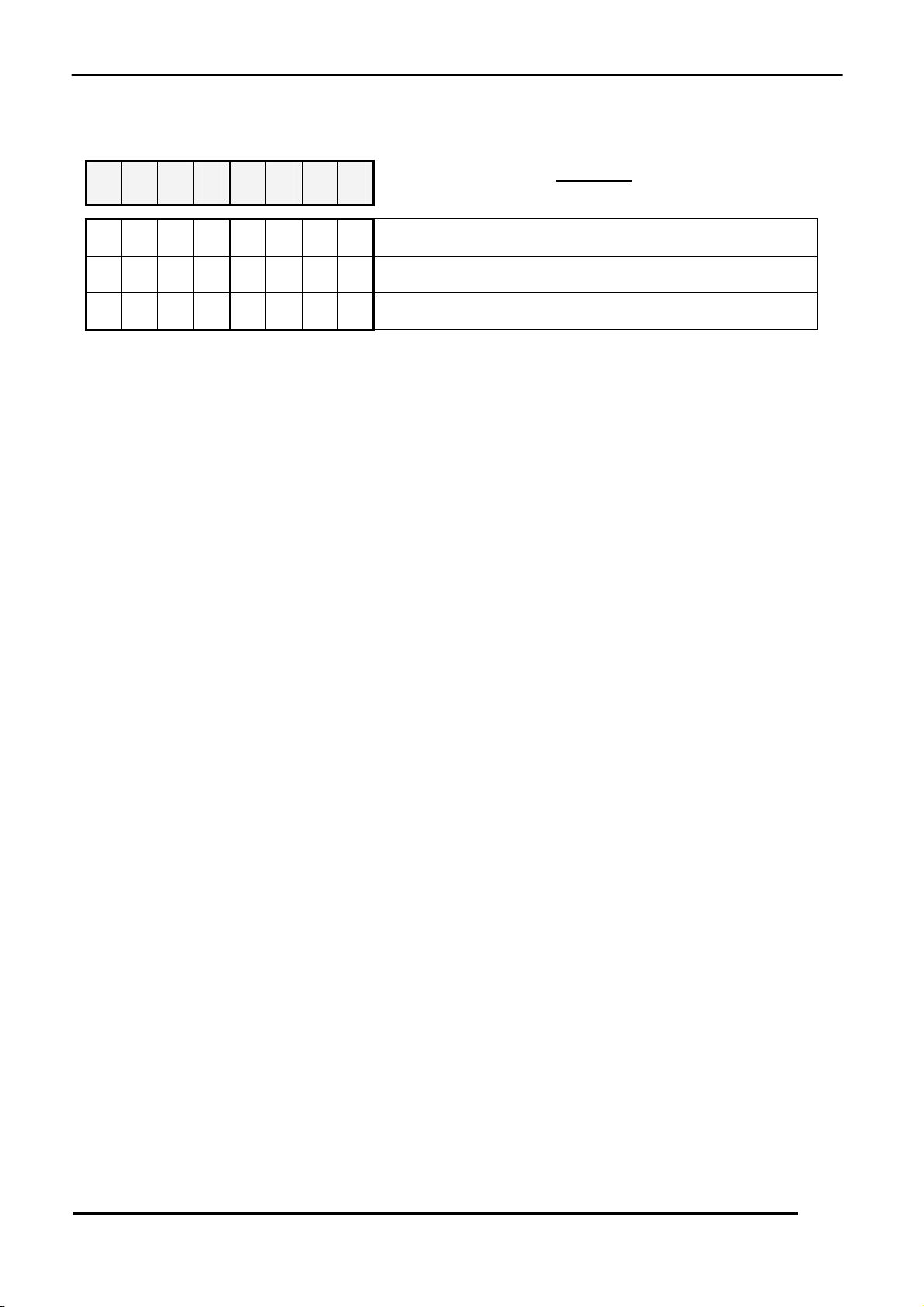
2.1 STRUCTURE OF A CHARCATER SENT OR RECEIVED BY THE ERCP81
- A start bit
- Eight data bits (the least significant bit is sent first).
- A parity bit (even parity)
- A stop bit.
The characters in the same message must not be separated by a time greater than the time it takes to
send two characters.