7FT-60R/E Technical Supplement
Circuit Description
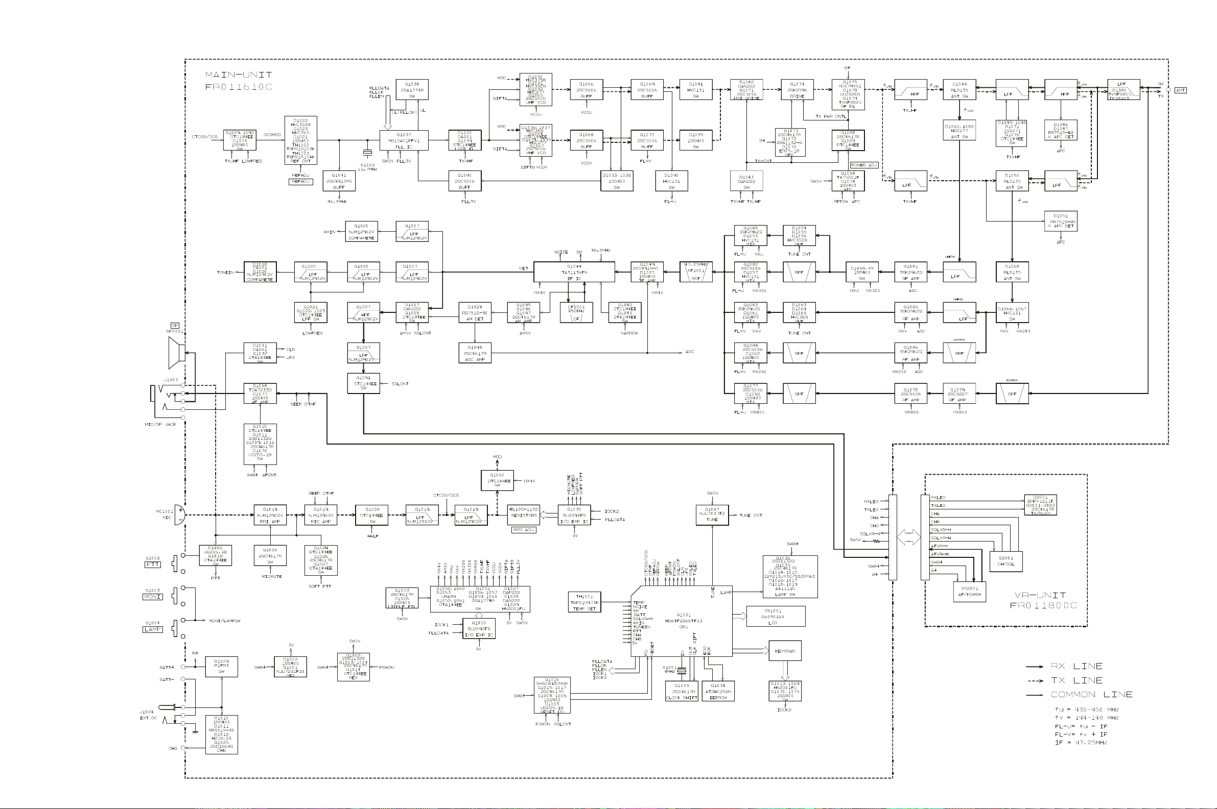
VHF Reception
Incoming VHF signal is passed through the low-pass fil-
ter network, antenna switching diode D1066 (HVC131)
and D1068 (RLS135), and low-pass filter network to the
RF amplifier Q1085 (3SK296ZQ). The amplified RF sig-
nal is passed through band-pass filtered again by varac-
tor-tuned resonators L1060, L1061 and L1062, and D1063,
D1064, and D1065 (all HVC365), then applied to the 1st
mixer Q1083 (3SK296ZQ) along with the first local signal
from the PLL circuit.
The first local signal is generated between 191.25 MHz
and 195.25 MHz by the VHF VCO, which consists of Q1067
(2SC5006), switching diodes D1034, D1035 (both
HSC277), and varactor diodes D1036, D1037 (both
HVC365) according to the receiving frequency.
UHF Reception
Incoming UHF signal is passed through the low-pass fil-
ter network, antenna switching diodes D1060 and D1082
(both HSC277), and Low-pass filter network to the RF am-
plifier Q1081 (3SK296ZQ). The amplified RF signal is
passed through band-pass filtered again by varactor-tuned
resonators L1049, L1050 and L1051, and D1054, D1055,
and D1056 (all HVC350B), then applied to the 1st mixer
Q1080 (3SK296ZQ) along with the first local signal from
the PLL circuit.
The first local signal is generated between 382.75 MHz
and 402.75 MHz by the UHF VCO, which consists of Q1065
(2SC5006) and varactor diodes D1030 (HVC375B), D1031
(HVC350B) and switching diode D1032 (HSC277) accord-
ing to the receiving frequency.
IF and Audio Circuits
The 47.25 MHz first IF signal is applied to the monolithic
crystal filters XF1001 which strip away unwanted mixer
products, and the IF signal is applied to the first IF ampli-
fier Q1049 (2SC4915). The amplified first IF signal is then
delivered to the FM IF subsystem IC Q1044 (TA31136FN),
which contains the second mixer, limiter amplifier, noise
amplifier, and FM detector.
The second local signal is generated by 46.8 MHz crystal
X1002 and Q1041 (2SC4915), produces the 450 kHz sec-
ond IF signal when mixed with first IF signal within Q1044
(TA31136FN).
The 450 kHz second IF signal is applied to the ceramic
filter CF1001 which strip away unwanted mixer products
to the ceramic discriminator CD1001 which removes any
amplitude variations in the 450 kHz IF signal before de-
tection of speech.
The detected audio passes through the de-emphasis net-
work, low-pass filter consisting of Q1007 (NJM12902V)
and associated circuitry, and high-pass filter consisting of
Q1007 (NJM12902V) and associated circuitry. The filtered
audio signal is applied to the audio volume, then passes
through the AF ampplifire Q1008 (TDA7233D) and MIC/
SP jack to the internal speaker or an external speaker.
Squelch Control
When no carrier received, noise at the output of the de-
tector stage in Q1044 (TA31136FN) is amplified and band-
pass filtered by the noise amp section of Q1044
(TA31136FN). The resulting DC voltage is applied to pin
47 of main CPU Q1031 (HD64F2266), which compares
the squelch threshold level to that which set by the SQL
knob.
While no carrier is received, pin 35 of Q1031 (HD64F2266)
remains “low,“ squelch gate Q1005 and Q1091 (both
DTC144EE) to turns off to disable any demodulated au-
dio pass.
Transmit Signal Path
The speech signal from the microphone to AF amplified
Q1019 (NJM12902V). The amplified speech signal passes
through low-pass filter network Q1019 (NJM12902V) to
deviation controlled by Q1030 (BU2090FS).
VHF Transmit Signal Path
The adjusted speech signal is delivered to VHF VCO
Q1067 (2SC5006) which frequency modulates the trans-
mitting VCO made up of D1037 (HVC365).
The modulated transmit signal passes through buffer
amplifier Q1068 and Q1070 (both 2SC5006).
The filtered transmit signal applied to the Pre-Drive am-
plifier Q1071 (2SC5006) and Drive amplifier Q1074
(2SK2596), then finally amplified by Power amplifier
Q1075 (RD07MVS1) up to 5 Watts. This two stages pow-
er amplifier's gain is controlled by the APC circuit.
The 5 Watts RF signal passes through low-pass filter net-
work, antenna switch D1050 (RLS135), and another low-
pass filter network, and then deliver to the ANT jack.
UHF Transmit Signal Path
The adjusted speech signal is delivered to UHF VCO
Q1065 (2SC5006) which frequency modulates the trans-
mitting VCO made up of D1030 (HVC375).
The modulated transmit signal passes through buffer
amplifier Q1066 and Q1069 (both 2SC5006).
The filtered transmit signal applied to the Pre-Drive am-
plifier Q1071 (2SC5006) and Drive amplifier Q1074
(2SK2596), then finally amplified by Power amplifier
Q1075 (RD07MVS1) up to 5 Watts. This two stages pow-
er amplifier's gain is controlled by the APC circuit.