Yaesu FTDX5000D HF - PRODUCT REVIEW 12-2010 User manual

From December 2010 QST © ARRL
PRODUCT REVIEW
Mark J. Wilson, K1RO
Product Review Editor
Reviewed by Rick Lindquist, WW3DE
Managing Editor,
National Contest Journal
Yaesu’s latest colossus rules, delivering
top tier performance at a substantially less
than a top tier price. The FTDX5000 series
establishes a new benchmark, the highest
close-in IMD dynamic range and third-order
intercept we’ve ever measured. It can and will
do the heavy lifting for the most demanding
DXer or contester.
This radio shares DNA with earlier Yaesu
offerings. Over the past several years, Yaesu
has deployed an array of such signature
signal enhancing features as Contour, VRF,
µ-Tune and Class A. As with the FT-2000
and FTDX9000 models reviewed previously,
the FTDX5000 builds upon this legacy, and
it may be helpful to reread those reviews
(you did read them already, right?).1 Three
FTDX5000 models are available according
to option package: The FTDX5000, the
FTDX5000D and the FTDX5000MP. The
basic 5000 is very well equipped. The D
model adds the SM-5000 monitor scope, and
the MP adds the SM-5000, 300 Hz roofing
filter (optional on the other models) and high
stability oven controlled crystal oscillator.
The FTDX5000D with optional 300 Hz
roofing filter reviewed here is a transceiver
for the discriminating contester or DXer,
who may even consider its roughly $6000
price a bargain. Although extremely rich in
performance, it lacks some “convenience”
features. For example, you cannot connect
a keyboard for digital modes or data entry.
Then again, you don’t put a backup cam on
an Indy car. Optional Yaesu accessories let
you trick out your ride.
Some Broad Strokes
Main (A) and subreceiver (B) perfor-
mance tops that of several vaunted radios
already on the market, although the main
Yaesu FTDX5000D HF and
6 Meter Transceiver
receiver does outperform the subreceiver (see
Table 1). The two discrete and comparable
receivers make it possible to transmit and/or
receive on separate bands — SO2R in a box
(details to come)!
Both receivers cover from 0.03 to 60 MHz.
Receiver A is double conversion, with the
first IF at 9 MHz and the second DSP IF at
30 kHz for SSB and CW and 24 kHz for AM
and FM modes. Receiver B is a triple-
conversion design, with the first and second
IFs at 40.455 MHz and 455 kHz, respectively,
and the DSP third IF identical to the second
IF in the main receiver. The 300 and 600 Hz
roofing filters are not available to the sub-
receiver.
The radio delivers 200 W on HF and
6 meters on SSB and CW. Yaesu advises
reducing the power to 1⁄2 to 1⁄3 of maximum
when using high duty cycle modes such
as RTTY or PSK31 for “longer than a few
minutes,” and rolling back to 50 W on AM.
As revisions become available, you can
update the radio’s firmware via an RS-232
port using files downloaded from the Internet.
Since most new PCs don’t come with RS-232
serial adapters/ports, USB would have been
a nice option; there are arguments on both
sides of this technological issue, however.
A serial to USB adapter (Prolific chipset)
worked fine for me. We did not perform a
firmware update on our review radio, since
this would have presented a moving target
for evaluating performance. The procedure
is relatively straightforward, and Yaesu has
resolved early issues with the update writer.
The FTDX5000 takes DSP noise reduc-
1The following QST Product Reviews
may be of interest: FT-2000 (Feb 2007),
FT-2000D (Oct 2007), FTDX9000D
(Aug 2005), FTDX9000 Contest (Mar 2006)
and FTDX9000MP (Jul 2010). Past QST
reviews are available to ARRL members
at www.arrl.org/product-review.
tion to a new level — absolutely the best
implementation I’ve ever experienced. It’s
just spectacular and could even make the
horrid racket from my neighbor’s solar array
system melt into the background.
To enhance selectivity, the ’5000 offers
a selection of six pole crystal roofing filters
(300 Hz, 600 Hz, 3 kHz, 6 kHz and 15 kHz
are available for the main receiver), a feature
several quality transceivers have begun of-
fering. On CW the 300 Hz roofing filter is
amazing. Coupled with a narrow DSP filter,
you can sidle up to the strongest signals on
the band to pull someone out.
In general, the radio’s various DSP
tools may impart some echo — the audio
equivalent to “ringing” — especially at more
extreme settings. This apparently is a result
of latency.
A 46.3 Pound Gorilla in the Shack
This is a substantial radio, although it
doesn’t match the girth or weight of the
FTDX9000MP reviewed in July 2010 QST,
nor that radio’s 400 W output. The ac power
supply is built in. The FTDX5000 presents
the user with a surfeit of knobs, buttons and
displays that let you know you’re at the helm.
The ample main tuning knob augments this
sense of control. It can be daunting at first.
Some controls probably could have been
relegated to menus; MIC gain, for example, is
not something you typically adjust on the fly.
The front panel layout is sensible, al-
though I did wish the legends were in a more
contrasting shade. Style does not triumph
over substance here. I’d expressed similar

From December 2010 QST © ARRL
Bottom Line
Key Measurements
Summary
An extraordinary transceiver for
the discerning contester or DXer.
This one will become the gold stan-
dard for operators seeking the best
receive performance and best value
in its class.
PR053
80 M
20 M
Values shown are for Receiver A
with 600 Hz roofing filter.
Dynamic range and intercept values
with preamp off.
Intercept values were determined using
-97 dBm reference.
* Blocking exceeded the levels indicated.
See Table 1.
‡ Class A operation.
Key: ** Off Scale
-20 -70
,
TX
Transmit 9th-order IMD (dB)
-72‡**
-47
-20 -35
TX
,
Transmit 3rd-Order IMD (dB)
-43‡**
-30
-40 +30
,
2
2 kHz 3rd-Order Intercept (dBm)
40**
-40 +35
,
20
20 kHz 3rd-Order Intercept (dBm)
41**
32
50 110
,
2
2 kHz 3rd-Order Dynamic Range (dB)
114**
50 110
,
20 114**
109
20 kHz 3rd-Order Dynamic Range (dB)
70 140
136*
136*
2 kHz Blocking Gain Compression (dB)
2
70 140
136*
136*
20 kHz Blocking Gain Compression (dB)
20
concerns in reviewing the FTDX9000 Contest
(see “Product Review,” Mar 2006 QST). On
the other hand, all readouts are easy on the
eyes. The three subdisplays are crisp, organic
light emitting diode types. The multipurpose
meter has a D’Arsonval movement. As in
earlier Yaesu incarnations, a system summary
panel, part of the main display, shows basic
signal paths and settings for the main receiver
(VFO A) and the subreceiver (VFO B) per the
antenna, attenuator, IPO, roofing filter and
AGC settings.
A couple of things struck me. First, there
is no separate indication on the main display
to let you know when VOX is enabled, beyond
a tiny red LED on the VOX button. Second,
there is no main display SPLIT indicator. You
must instead pay attention to whether the
TX indicator adjacent to the VFO B knob is
illuminated. (You’ll also see the TX indicator
switch to VFO B when transmitting.).
The VFO A and VFO B subdisplays con-
tinue to show the set value, even after the
function is off. For example, if you turn off the
NR, the display dims, and turning the knob still
changes the displayed setting while not affect-
ing reception. Enabling another function shifts
the subdisplay’s focus to the new function.
Through menus, the operator can set indi-
vidual brightness levels for the analog meter,
main frequency display, subdisplays and
SM-5000 when the DIM switch is pressed.
Color and contrast are not adjustable. There
are several color choices for the SM-5000
screen, but color and contrast are not adjust-
able on the main radio displays.
The FH-2 keypad accessory can be used
for controlling the built-in CW memory keyer
and voice keyer, as well as for frequency
adjustments.
At first I didn’t figure the FH-2
would come in handy, but it turned out to be
just the thing for those times when you’re
repeatedly calling a DX station that’s gener-
ated a massive pileup (and you’re running
200 W to wires).
A Problem Solved
Out of the box, our ’5000 would not key
properly, especially with an external keying
source. We found dit shortening at 60 WPM,
which was not affected by the waveform
shaping menu or by adjusting the break-in
(QSK) delay. In addition, while using the
internal keyer in full break-in, unwanted
spikes materialized between dits above
33 WPM, possibly a result of some sort of
relay bounce. ARRL Lab Test Engineer Bob
Allison, WB1GCM, described these as “phan-
tom spikes” that looked “like triangles in the
blank spaces between dits, causing a not so
pretty keying waveform.”
A Yaesu-provided circuit modification
fixed the problem. The manufacturer says
its production line incorporated the keying
modification starting with Lot 2, although
not all Lot 2 radios were modified. The
problem has been corrected in all Lot 3
and later radios, however, and Yaesu says
it will fix any radios already in the hands
of customers.
A Problem Unsolved
So called “spurs” in the ’5000’s main
receiver generated considerable chatter
among owners and wannabes on the Yaesu
FTDX5000 reflector. While Yaesu is looking
into this issue, it remained unresolved as this
review went to press. Here’s the thing: You
have to be looking for these artifacts (they are
not “spurs” in the true sense of the word) in
order to hear them. If the radio is set for 1 Hz
resolution and a signal — preferably a strong
one — is on or near certain frequencies in
certain bands, you can hear a faint blip as you
turn the VFO knob past certain other specific
frequencies. They’re easy to miss altogether
and may give the impression of tuning past a
real signal very quickly, but there is no spur
that you can actually tune to. Some users
consider this a serious issue that’s deserving
of Yaesu’s attention.
High Fidelity
SSB enthusiasts will enjoy the FTDX5000’s
comprehensive transmit audio tailoring capa-
bilities using the three octave equalizer. There
are two tiers of settings — one for when the
processor is off, the other for when it’s on.
The PROC button steps through MIC EQ and
PROC steps, as indicated on the main display.
These settings allow you to adjust gain,
bandwidth and even Q for each bandwidth
range in the equalizer, punching up one range
of frequencies and tempering another to suit
your voice. This is akin to the sort of audio
processing broadcasters use on their studio
microphones to make even the most modest
voice sound appreciably more robust.
The equalizer can take some time to set up,
and for situations in which multiple operators
will be using the radio, you may just want to
go with the flat response defaults and trim
your audio using any adjustments available
on your mic or headset. The radio is capable
of enhanced SSB (ESSB) operation. The
FTDX5000 offers similarly extensive audio
tweaking capabilities for the receivers’ audio.
Intercept Point Optimization
and Preamps
Yaesu employs IPO buttons on its HF
transceivers. The ’5000’s main receiver has
two IPO settings, IPO1 and IPO2; the subre-
ceiver has just IPO1. IPO stands for intercept
point optimization, referring to third order
intercept point (IP3), a popular metric that
takes into account a receiver’s sensitivity and
dynamic range (see Table 1). What the IPO
buttons actually do is turn off any preamps,
which typically degrade dynamic range.
Pushing the IPO button can improve the
dynamic range on a band that has external

From December 2010 QST © ARRL
Table 1
Yaesu FTDX5000, serial number 00020034
Manufacturer’s Specifications Measured in the ARRL Lab
Frequency coverage: Receive, 0.03-60 MHz; Receive and transmit, as specified.
transmit, 1.8-2, 3.5-4, 5.3305, 5.3465, 5.3665,
5.3715, 5.4035, 7-7.3, 10.1-10.15, 14-14.35,
18.068-18.168, 21-21.44, 24.89-24.99, 28-29.7,
50-54 MHz.
Power consumption at 117 V ac: receive, Receive, no signal, 61 VA; receive signal
no signal, 70 VA; signal present, 80 VA, present, max audio, 66 VA; transmit,
transmit, 200 W output, 720 VA. 481 VA at 200 W RF output.
Modes of operation: SSB, CW, AM, FM, RTTY, As specified.
PKT.
Receiver Receiver Dynamic Testing,
Receiver “A”
SSB/CW sensitivity: 2.4 kHz bandwidth, Noise floor (MDS), 500 Hz bandwidth,
10 dB S+N/N: 0.5-1.8 MHz, 2.0 µV; 600 Hz roofing filter:
1.8-30 MHz, 0.2 µV (Amp 2); 50-54 MHz, Preamp Off 1 2
1.25 µV (Amp 2). Preamp not available (dBm) (dBm) (dBm)
below 1.8 MHz. 0.137 MHz –116 — —
0.505 MHz –117 — —
1.0 MHz –118 — —
3.5 MHz –126 –136 –143
14 MHz –126 –136 –142
50 MHz –120 –131 –140
Noise figure: Not specified. 14 MHz, preamp off/1/2: 21/11/5 dB
AM sensitivity: 6 kHz bandwidth, 10 dB S+N/N: 10 dB (S+N)/N, 1-kHz, 30% modulation,
0.5-1.8 MHz, 6 µV; 1.8-30 MHz, 2 µV (Amp 2); 9 kHz filter, 15 kHz roofing filter:
6 meters, 1 µV (Amp 2). 1.0 MHz 8.60 µV
3.8 MHz 0.47 µV (Preamp 2 on)
50 MHz 0.59 µV (Preamp 2 on)
FM sensitivity: 15 kHz bandwidth, 12 dB SINAD: For 12 dB SINAD, preamp 2 on:
0.1-30 MHz, 0.5 µV (Amp 2); 50-54 MHz, 29 MHz 0.22 µV
0.35 µV (Amp 2) 52 MHz 0.23 µV
Spectral display sensitivity: Not specified. –115 dBm maximum with optional
SM-5000 station monitor.
Blocking gain compression: Not specified. Gain compression, 500 Hz bandwidth,
600 Hz roofing filter:
20 kHz offset 5/2 kHz offset
Preamp off/1/2 Preamp off
3.5 MHz 136*/146/142 dB 136*/136* dB
14 MHz 136*/146/142 dB 136*/136* dB
50 MHz 130*/141/137 dB 130*/127 dB
Reciprocal Mixing (500 Hz BW): Not specified. 20/5/2 kHz offset: –109/–109/–104 dBc.
ARRL Lab Two-Tone IMD Testing (300 Hz bandwidth, 300 Hz roofing filter)**
Measured Measured Calculated
Band/Preamp Spacing Input Level IMD Level IMD DR IP3
3.5 MHz Off 20 kHz –17 dBm –126 dBm 109 dB +38 dBm
–11 dBm –97 dBm +32 dBm
14 MHz/Off 20 kHz –12 dBm –126 dBm 114 dB +45 dBm
–5 dBm –97 dBm +41 dBm
0 dBm –84 dBm +42 dBm
14 MHz/Pre 1 20 kHz –24 dBm –136 dBm 112 dB +34 dBm
–22 dBm –97 dBm +28 dBm
14 MHz/Pre 2 20 kHz –36 dBm –143 dBm 107 dB +18 dBm
–22 dBm –97 dBm +16 dBm
14 MHz/Off 5 kHz –12 dBm –126 dBm 114 dB +45 dBm
–6 dBm –97 dBm +40 dBm
0 dBm –82 dBm +41 dBm
14 MHz/Off 2 kHz –12 dBm –126 dBm 114 dB +45 dBm
–6 dBm –97 dBm +40 dBm
0 dBm –82 dBm +41 dBm
50 MHz/Off 20 kHz –14 dBm –120 dBm 106 dB +39 dBm
–8 dBm –97 dBm +37 dBm
Second-order intercept point: Not specified. 14 MHz, Preamp off/1/2: +65/+71/+71 dBm.
DSP noise reduction: Not specified. Variable, 30 dB maximum.
Notch filter depth: Not specified. Manual: >70 dB, auto: >70 dB.
Attack time: 60 ms.
FM two-tone, third-order IMD dynamic range: 20 kHz offset, Preamp 2: 29 MHz,
Not specified. 100 dB†; 52 MHz, 96 dB†.
10 MHz channel spacing: 52 MHz, 91 dB.
noise well above the receiver noise. This
doesn’t show up in lab testing, but can make
a dif ference with an antenna connected —
especially on the bands lower in frequency
than 14 MHz.
Just why the main receiver has two IPO
levels is unclear. The IPO2 setting routes the
signal directly to the first mixer. The manual
says only that the IPO1 setting “improves
the IPO.” The radio also has twin preamps,
and Yaesu recommends using PREAMP1 for
the higher bands (there are three levels of
attenuation as well). I found no occasions
when I needed to use PREAMP2, although
the attenuator came in handy.
SO2R in a Box!
A growing number of contesters are
adopting the single operator/two radio
(SO2R) operating model. The SO2R shack
utilizes two transceivers. The main trans-
ceiver is the “run radio” for calling CQ;
the secondary transceiver is the “multiplier
radio” for tuning around. The typical SO2R
setup also employs separate antennas for
each transceiver.
The FTDX5000 opens the door to SO2R
with a single box and, if desired, just one
antenna. Both receivers can use the same
antenna at the same time, although with four
antenna ports on the rear apron, they don’t
have to. While running SO2R you can still
log contacts as though you were using one
radio. Swapping the transmit VFO from B
to A lets your logger record the contact on
the correct band.
The Stats
Subjective observations aside, the num-
bers tell the big story here. Don’t be misled
by nomenclature. Both FTDX5000D receiv-
ers outperform the FTDX9000MP’s roughly
equivalent receivers in terms of dynamic
range and IP3.
For Receiver A, at the where-it-really-
matters 2 kHz spacing, the two-tone third-
order IMD dynamic range at 14 MHz is
just as good as at 20 kHz spacing. In all
cases, IMD dynamic range was well over
100 dB. This is the receiver with a 9 MHz
first IF and narrow roofing filters, currently
the hot setup for top-of-the-line close-in
dynamic range. One interesting phenomenon
was noted during the testing. The sensitivity
(MDS) of receiver A lowered by a few dB
after the radio had been in use for a few hours.
This did not change the excellent measured
dynamic performance. This represents excel-
lent real-world performance, which holds up
right through 6 meters!
For Receiver B, with a VHF IF and without
the narrow roofing filters, the worst-case dy-
namic range was 88 dB on 14 MHz at 2 kHz
spacing; all other numbers were in the 90s, the
best being 98 dB on 14 MHz at 5 kHz spacing,
yielding an IP3 of +25 dBm.

From December 2010 QST © ARRL
Figure 1 — CW keying waveform for the
FTDX5000D showing the first two dits in full
break-in (QSK) mode using external keying.
Equivalent keying speed is 60 WPM. The
upper trace is the actual key closure; the
lower trace is the RF envelope. (Note that
the first key closure starts at the left edge
of the figure.) Horizontal divisions are
10 ms. The transceiver was being operated
at 200 W output on the 14 MHz band.
Figure 3 — Spectral display of the
FTDX5000D transmitter output during
composite-noise testing. Power output is
200 W on the 14 MHz band. The carrier, off
the left edge of the plot, is not shown. This
plot shows composite transmitted noise
100 Hz to 1 MHz from the carrier. The refer-
ence level is 0 dBc, and the vertical scale
is in dB.
Figure 2 — Spectral display of the
FTDX5000D transmitter during keying
sideband testing. Equivalent keying speed
is 60 WPM using external keying. Spectrum
analyzer resolution bandwidth is 10 Hz,
and the sweep time is 30 seconds. The
transmitter was being operated at 200 W
PEP output on the 14 MHz band, and this
plot shows the transmitter output ±5 kHz
from the carrier. The reference level is
0 dBc, and the vertical scale is in dB.
Time (s)
0 0.01 0.02 0.03 0.04 0.05 0.06 0.07 0.08
QS1012-Prodrev01
&+
&+
Reponse, dB
Frequency in kHz
fc
fc-4 fc-2 fc+2 fc+4
QS1012-Prodrev02
1x1021x10 31x1041x10 51x10 6
-180
-160
-140
-120
-100
-80
-60
-40
-20
0
Response in dB
Frequency in Hz
QS1012-Prodrev03
[Table 1 continues on next page.]
Receiver Receiver Dynamic Testing,
Receiver “B”
S-meter sensitivity: Not specified. S9 signal at 14.2 MHz, preamp off/1/2,
135/36/10 µV.
Squelch sensitivity: Not specified. At threshold: SSB, 14.6 µV; FM, 29 MHz
(preamp 2), 0.32 µV; 52 MHz, 0.12 µV.
Receiver audio output: 2.5 W into 2.8 W at 8.7% THD into 4 W.
4 W at 10% THD. THD at 1 V RMS: 0.7%.
IF/audio response: Not specified. Range at –6 dB points, (bandwidth): ‡
CW (500 Hz filter): 435-950 (515 Hz) ‡
Equivalent Rectangular BW: 506 Hz
USB: (2.4 kHz filter): 268-2628 (2360 Hz)
LSB: (2.4 kHz filter): 268-2622 (2354 Hz)
AM: (9 kHz filter): 137-3410 (6546 Hz).
Spurious and image rejection: 160-10 meters, First IF, 14 MHz, 99 dB; 50 MHz, >111** dB;
>70 dB; 50-54 MHz, >60 dB. image, 14 MHz, 60 dB; 50 MHz, 73 dB.
SSB/CW sensitivity: 2.4 kHz bandwidth, Noise floor (MDS), 500 Hz bandwidth,
10 dB S+N/N: 0.5-1.8 MHz, 2.0 µV; 3 kHz roofing filter:
1.8-30 MHz, 0.2 µV (Amp 2); 50-54 MHz, Preamp Off 1 2
1 µV (Amp 2). (dBm) (dBm) (dBm)
0.137 MHz –111 — —
0.505 MHz –113 — —
1.0 MHz –113 — —
3.5 MHz –124 –133 –137
14 MHz –122 –132 –136
50 MHz –120 –131 –136
Noise Figure: Not specified. 14 MHz, preamp off/1/2, 25/15/11 dB
AM sensitivity: 6 kHz bandwidth, 10 dB S+N/N: 10 dB (S+N)/N, 1-kHz, 30% modulation,
0.5-1.8 MHz, 6 µV; 1.8-30 MHz, 2 µV (Amp 2); 9 kHz filter, 15 kHz roofing filter:
6 meters, 1 µV (Amp 2). 1.0 MHz 15.1 µV
3.8 MHz 0.86 µV (Preamp 2 on)
50 MHz 1.16 µV (Preamp 2 on)
FM sensitivity: 15 kHz bandwidth, 12 dB SINAD: For 12 dB SINAD, preamp 2 on:
0.1-30 MHz, 0.5 µV (Amp 2); 50-54 MHz, 29 MHz 0.46 µV
0.35 µV (Amp 2) 52 MHz 0.46 µV
Blocking gain compression: Not specified. Gain compression, 500 Hz bandwidth,
3 kHz roofing filter:
20 kHz offset 5/2 kHz offset
Preamp off/1/2 Preamp off
3.5 MHz 130/134/129 dB 126/105 dB
14 MHz 130/133/128 dB 126/106 dB
50 MHz 129/133/127 dB 122/103 dB
Reciprocal Mixing (500 Hz BW): Not specified. 20/5/2 kHz offset: –109/–101/–94 dBc.
ARRL Lab Two-Tone IMD Testing (500 Hz bandwidth, 3 kHz roofing filter)**
Measured Measured Calculated
Band/Preamp Spacing Input Level IMD Level IMD DR IP3
3.5 MHz Off 20 kHz –26 dBm –124 dBm 98 dB +23 dBm
–17 dBm –97 dBm +23 dBm
14 MHz/Off 20 kHz –24 dBm –122 dBm 98 dB +25 dBm
–16 dBm –97 dBm +25 dBm
0 dBm –53 dBm +27 dBm
14 MHz/Pre 1 20 kHz –34 dBm –132 dBm 98 dB +15 dBm
–23 dBm –97 dBm +14 dBm
14 MHz/Pre 2 20 kHz –42 dBm –136 dBm 94 dB +5 dBm
–29 dBm –97 dBm +5 dBm
14 MHz/Off 5 kHz –24 dBm –122 dBm 98 dB +25 dBm
–14 dBm –97 dBm +28 dBm
0 dBm –52 dBm +26 dBm
14 MHz/Off 2 kHz –34 dBm –122 dBm 88 dB +10 dBm
–17 dBm –97 dBm +28 dBm
0 dBm –52 dBm +26 dBm
50 MHz/Off 20 kHz –27 dBm –120 dBm 93 dB +20 dBm
–20 dBm –97 dBm +19 dBm
Second-order intercept point: Not specified. 14 MHz, Pre off/1/2: +71/+37/+31 dBm.
DSP noise reduction: Not specified. Variable, 30 dB maximum.
Notch filter depth: Not specified. Manual notch: >70 dB, auto: >70 dB.
Attack time: 64 ms.

From December 2010 QST © ARRL
Receiver Receiver Dynamic Testing,
Receiver “B”
FM two-tone, third-order IMD dynamic range: 20 kHz offset, Preamp 2: 29 MHz,
Not specified. 84 dB†; 52 MHz, 85 dB†.
10 MHz spacing: 52 MHz, 87 dB.
S-meter sensitivity: Not specified. S9 signal at 14.2 MHz: preamp off/1/2:
240/69/26 µV.
Squelch sensitivity: Not specified. At threshold: SSB, 24.8 µV; FM, 29 MHz
(preamp 2), 1.10 µV; 52 MHz, 1.49 µV.
Receiver audio output: 2.5 W into 2.3 W at 1.0% THD into 4 W.
4 W at 10% THD. THD at 1 V RMS: 1%.
IF/audio response: Not specified. Range at –6 dB points, (bandwidth): ‡
CW (500 Hz): 391-928 Hz (537 Hz) ‡
Equivalent Rectangular BW: 531 Hz
USB: (2.4 kHz): 147-2417 Hz (2270 Hz)
LSB: (2.4 kHz): 144-2395 Hz (2251 Hz)
AM: (9 kHz): 116-2845 Hz (5458 Hz).
Spurious and image rejection: 160-10 meters, First IF reject, 14 MHz, 89 dB; 50 MHz,
>70 dB; 50-54 MHz, >60 dB. 44 dB; image reject, 14 MHz, 101 dB;
50 MHz, 48 dB.
Transmitter Transmitter Dynamic Testing
Power output: 10-200 W, (5-50 W AM); CW, SSB, RTTY, FM, typ 10-202 W, AM,
10-75 W (Class A mode, SSB). 4-67 W; Class A (SSB), typ 10-75 W PEP.
Spurious-signal and harmonic suppression: Worst: 54 dBc emission at 19.460 MHz,
>60 dB, 1.8-54 MHz. carrier freq of 21.020 MHz at 10 W RF
output. Meets FCC requirements.
SSB carrier suppression: >60 dB. As specified.
Undesired sideband suppression: >60 dB. As specified.
Third-order intermodulation distortion (IMD) 3rd/5th/7th/9th order (worst case):
products: –31 dB @ 14 MHz, 100 W PEP HF, 200 W PEP, –30/–48/–46/–47 dB;
below peak output, -40 dB, Class A, 75 W HF, Cl A 75 W PEP, –43/–64/–68/–72 dB;
PEP below peak output.
50 MHz, 200 W PEP, –30/ –48/–52/–58 dB.
CW keyer speed range: Not specified. 4 to 56 WPM.
CW keying characteristics: Not specified. See Figures 1 and 2.
Transmit-receive turn-around time (PTT release S9 signal, AGC fast, 66 ms.
to 50% audio output): Not specified.
Receive-transmit turn-around time (tx delay): SSB, 37 ms; FM, 36 ms.
Not specified.
Composite transmitted noise: Not specified. See Figure 3.
Size (height, width, depth): FTDX5000D 5.3 × 18.2 × 15.3 inches; weight, 46.3 lbs;
SM-5000 station monitor: 1.8 × 18.5 × 7.2 inches; weight, 5.5 pounds.
Price: FTDX5000D, $5500; XF-126CN 300 Hz roofing filter, $170.
*Exceeded figures indicated, +10 dBm maximum output from test fixture.
**ARRL Product Review testing now includes Two-Tone IMD results at several signal levels.
Two-Tone, 3rd-Order Dynamic Range figures comparable to previous reviews are shown on the
first line in each group. The optional 300 Hz roofing filter (standard on MP) was used. The 600 Hz
filter gave similar results. The “IP3” column is calculated Third-Order Intercept Point. Second-order
intercept points were determined using –97 dBm reference.
†Measurement was noise-limited at the value indicated.
‡Default values; bandwidth and cutoff frequencies are adjustable via DSP.
CW bandwidth varies with PBT and Pitch control settings.
Going Digital
There are separate RTTY (FSK) and PKT
(packet) modes and jacks; the PKT jack works
for AFSK data modes such as PSK31, what the
manual calls “SSB-based AFSK data modes.”
You can adjust various AFSK and RTTY pa-
rameters separately via the menu. It will do
either HF PKT (LSB) or FM PKT. In our radio
the IF notch did not function in the USB/PKT
setting, only in LSB/PKT. Yaesu has addressed
this via a firmware update. It’s possible to set
up AFSK modes to work in VOX mode, obvi-
ating the need for a PTT connection.
SM-5000 Spectrum Scope
The separate SM-5000 spectrum scope
comes standard with the D and MP models.
Yaesu provides hardware to secure it in place
atop the radio. I have to agree with those who
deem the speakers in the SM-5000 spectrum
scope terrific. The spectrum scope display,
however, is not terribly sensitive to weak
signals, which seem to hover at or below
the horizon. It’s two tone and best viewed
straight-on. Perhaps I’ve been spoiled by
the color spectrum scopes on other radios.
The SM-5000’s PEAK HOLD is great
for seeing CW signals, which can be rather
evanescent otherwise. Signal levels must be
fairly high before they’re very visible on the
scope, although maybe that’s just because
I don’t have three elements at 150 feet on
40 meters. The menu’s LBWC 1 setting shows
what’s in your immediate and general vicin-
ity, depending upon the selected frequency
span (25 to 2500 kHz).
Automatic Antenna Tuner
The effective automatic antenna tuner
puts out a low level signal when it’s working.
Heard on another receiver, this sounds a bit
like PSK31. When it’s in action you can hear
the relays clicking as the tuner seeks the most
appropriate component combination to bring
the SWR into line. The ATU does not affect
the received signal.
During initial setup, the tuner takes a little
time to find a match and memorize settings
for a given frequency (The tuner reserves
one main setting for each band; the other
89 are up for grabs.) The next time it tunes
to that frequency, it checks the memory and
quickly makes adjustments. This means that
if you use more than one antenna for a given
band and, as I do, have only one feed line
coming into the shack and a remote switch
outside, you will have to retune as you swap
antennas. Our FTDX5000 would not recall
ATU memory settings after powering down.
Yaesu has since corrected this via a firmware
update.
Simply Awesome!
Yaesu has scored several home runs with
the FTDX5000. Here are a few highlights
we’ve not yet mentioned, in random order.
Figure 4 — Close-
up of the main
display and
SM-5000 station
monitor screen.
To the left of the
frequency display
is information
about the status
of antenna,
attenuator, filter,
preamp, roofing
filter and AGC
settings for each
receiver.

From December 2010 QST © ARRL
Another Perspective
Well-known Delaware contester and DXer Jon Zaimes, AA1K, ran the
FTDX5000 through its paces. Here are his observations.
A lot of features will take a more thorough absorption of the manual to master;
a few things didn’t seem very intuitive, and I’m a longtime previous Yaesu user.
But it certainly has the feel of a quality radio, and I really like the way it sounds! It
has a quiet band floor and handles noise very well.
The receiver seems nice and tight. I never encountered any problems with
overload while tuning across the band, even with the 20 meter Yagi stack aimed
toward Europe and many strong signals. While transmitting on a separate radio
on 1820.6 kHz with 1.5 kW and with no extra band-pass filters in line, I could hear
no interference across 20 meters while beaming right at the transmitting antenna.
The 300 Hz roofing filter really makes for nice tight skirts on CW. The APF also
was very effective for isolating really close-in signals, making the desired one pop
right up.
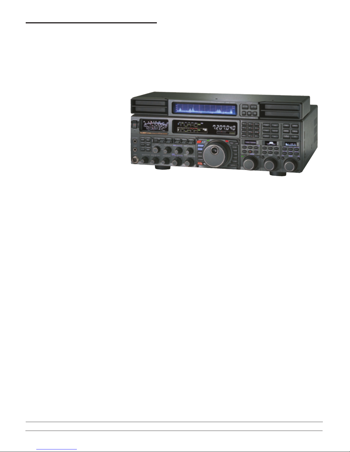
The separate SM-5000 band display makes it easy to find signals on a quiet
band. A way to “point and shoot” with a mouse would be nice. Also, I never found
a setting that yielded optimal contrast yet was still bright enough.
Some ergonomic concerns: If sitting upright at normal distance to reach tuning
knob and other controls, one cannot see the top of the S meter and the top row
of labels of the main display. In addition, the light-gray lettering on the charcoal
panel is very difficult to read, even under bright lighting, and this made for a more
difficult learning curve.
I found the relative placement of the VFO A and VFO B AF GAIN controls confus-
ing. The VFO B control is to the left of the VFO A AF GAIN control, but the VFO A and B
subdisplay clusters are just the opposite. For me this was counterintuitive.
At first I thought the ATU was going bonkers as the dial lights flashed HI SWR and
TUNE in rapid succession after I held in the TUNE button. But after a few seconds it
had tuned the radio to a flat SWR on 7295 kHz with my 40 meter beam, which is
cut for the low end of CW and has a high SWR at the high end. Nice!
Some front-panel buttons have an integrated LED to indicate when the func-
tion is on, but others do not. You have to look at the main display to see if the
function has been toggled on or off.
The very effective DSP CONTOUR fea-
ture allows additional filter shaping within
the receive passband.
The FTDX5000 has two notches. The
IF notch can be set to narrow or wide via
the menu. The DNF (digital notch filter) is
automatic and fixed.
Everyone’s radio should have the FT-
DX5000’s CW tuning guide, especially those
folks who persist in calling you 300 Hz off
frequency when you’re running a tight filter.
You can repurpose the CW tuning guide to
serve as a CLAR (clarifier or RIT) offset bar.
The APF is great, particularly on CW.
It lets you tease otherwise barely audible
stations out of the noise.
You can toggle between narrow and
wide noise blanker settings.
It’s possible to set certain parameters to
be band-specific.
The menu permits a wide range of DSP
filter customization, including steep, medium
or gentle shape factors.
When setting certain parameters, such as
RF output or keyer speed, its value appears
briefly on the main display.
The MONI knob also sets the CW
sidetone level, typically a separate adjust-
ment on lesser transceivers (and some-
times hidden in a menu).
The VRF, inserted in the signal path
between the antenna and the band-pass filter
and RF amplifier, is handy to enhance noise
reduction on a very noisy band, although it’s
not really intended for that.
The NAR (narrow) button is an excellent
feature that expands the WIDTH range down-
ward to 500 Hz or less for a given receiver.
This two-tier system lets you use the NAR
button to toggle between one very narrow
setting and one not-so-narrow setting.
The CLASS A setting greatly reduces
third and fifth-order transmit IMD (ie, “splat-
ter”) at a 75 W output level that’s sufficient
for most amplifiers.
The full break-in keying sounds great,
but as is the case with many radios you can
hear the TR relay clicking along as you send.
The FTDX5000 provides two options
for filling CW keyer memories: Send the
desired message and record it in one of the
memory positions, or “dial in” the text, one
character at a time, using the text message
programming setting.
The cooling fan is whisper quiet.
Not So Much
Despite its overall outstanding perfor-
mance, our FTDX5000 did not quite repre-
sent the apex of Amateur Radio transceiver
enterprise. Yaesu has addressed several is-
sues through firmware updates or hardware
modifications, but others are simply design
drawbacks. Here are some kinks we spotted,
again in no particular order.
A front panel label on earlier-run FT-
DX5000s (including ours) misspelled the
word “transceiver.” This has been fixed in
later production runs, and some already are
calling units bearing the TRANCEIVER label
“The Collectors’ Edition.”
The 176 item menu system is a huge
improvement over what I’ve seen from
Yaesu in the past, but it still mandates oc-
casional visits to the manual to decipher.
Other manufacturers have implemented
plain language menus; Yaesu is behind the
curve on this one.
The 144 page Operating Manual has a
lot of information about setting up and using
the many features this radio offers, but it
could use some improvement. Among other
things it lacks a CAT reference as well as a
detailed index, although Yaesu does provide
supplementary information on its Web site.
The downloadable PDF version is easily
searchable.
I detected a low level hum or tone when
turning the VFO A AF GAIN control past about
12 o’clock. Yaesu said it would look into this.
With headphones connected, the speaker
comes on for about a second when you turn
off the radio.
Close the Door and Have a Seat
The FTDX5000 represents a giant leap
forward for Yaesu in the high end transceiver
market, and it already has begun to attract an
enthusiastic following.
Given the FTDX5000’s price class and in-
tended market, we are compelled to comment
on the apparent lack of attention to some
details. [Of course as noted in other reviews,
Yaesu is not alone in making updates as is-
sues are discovered in early release radios.
Another way to look at it is that in previous
generations of radios, fixes to major problems
were slow to come and minor issues were
rarely resolved. — Ed.]
As noted throughout the review, Yaesu
has addressed reported issues through firm-
ware updates or hardware modifications (in
some cases requiring the radio to be shipped
back for service). Current production radios
should not exhibit many of the issues encoun-
tered in our early production model.
Yaesu is to be commended for combining
top tier receiver performance and a clean
Class A transmitter with the features and
functions users expect, all in a competitively
priced package.
Manufacturer: Vertex Standard, 10900
Walker St, Cypress, CA 90630; tel 714-827-
7600; www.yaesu.com.
Table of contents
Other Yaesu Transceiver manuals

Yaesu
Yaesu FTV-107R User manual

Yaesu
Yaesu FT-2000D User manual

Yaesu
Yaesu FTM-100DR User manual

Yaesu
Yaesu CPU-2500R User manual

Yaesu
Yaesu FT-727R User manual

Yaesu
Yaesu FT-902DM User manual

Yaesu
Yaesu FTM-300DR User manual

Yaesu
Yaesu FTDX1200 Series Owner's manual

Yaesu
Yaesu FT-290R User manual

Yaesu
Yaesu FTM-400XD User manual

Yaesu
Yaesu VX-3R User manual

Yaesu
Yaesu FTM-3100E User manual

Yaesu
Yaesu FT-212RH User manual

Yaesu
Yaesu FTdx5000 Series User manual

Yaesu
Yaesu FT-991 User manual

Yaesu
Yaesu FTA-450 series User manual

Yaesu
Yaesu FT-11R User manual

Yaesu
Yaesu FT-991 User manual

Yaesu
Yaesu FT-857D User manual

Yaesu
Yaesu VX-7R User manual