Seada GENESIS 265 User manual

GENESIS™265 User Guide
This user guide provides instructions for setting up SEADA GENESIS™265 using the G265
UMPlatform, G265 Designer Software and G265 Client.

Table of Contents
1. G265 Introduction..........................................................................................................................1
1.1. G265 Overview................................................................................................................................... 1
1.2. Key Features....................................................................................................................................... 1
1.3. Specifications ..................................................................................................................................... 2
1.4. Models................................................................................................................................................ 2
1.5. System Diagram ................................................................................................................................. 2
2. Connection Setup...........................................................................................................................3
2.1. Set up the G265 transceiver............................................................................................................... 3
2.2. Ethernet (LAN) connection with the control PC................................................................................. 3
3. Config the G265 transceiver............................................................................................................4
3.1. Main Tabs........................................................................................................................................... 4
3.2. Information Tabs................................................................................................................................ 5
3.3. Sub Tabs –Input (Encoder –TX) ........................................................................................................ 6
3.4. Sub Tabs –Output (Decoder –RX)..................................................................................................... 8
4. G265 Designer Software User Guide .............................................................................................10
4.1. Login Window .................................................................................................................................. 10
4.2. Designer Menu................................................................................................................................. 11
4.3. Designer Tool Menu......................................................................................................................... 12
4.4. UI Design Area.................................................................................................................................. 13
4.5. UI Tool Menu.................................................................................................................................... 14
4.6. UI Design –UI Menu ........................................................................................................................ 15
4.6.1. New Page .................................................................................................................................. 16
4.6.2. Rectangle .................................................................................................................................. 18
4.6.3. Text ........................................................................................................................................... 19
4.6.4. Button ....................................................................................................................................... 20
4.6.5. Slider ......................................................................................................................................... 22
4.6.6. Signal......................................................................................................................................... 23
4.6.7. Panel ......................................................................................................................................... 24
4.6.8. List............................................................................................................................................. 25
4.6.9. Get back .................................................................................................................................... 26
4.6.10. Matrix...................................................................................................................................... 27

4.7. Panel Setting .................................................................................................................................... 28
4.7.1. Scan Output .............................................................................................................................. 28
4.7.2. Bind windows to outputs.......................................................................................................... 28
4.7.3. Mode......................................................................................................................................... 28
4.7.4. Audio Follow ............................................................................................................................. 28
4.8. Input Setting..................................................................................................................................... 29
4.8.1. Scan Input ................................................................................................................................. 29
4.8.2. Config Inputs............................................................................................................................. 29
4.8.3. New Group................................................................................................................................ 29
4.8.4. Group Signal.............................................................................................................................. 29
4.9. User.................................................................................................................................................. 30
4.9.1. New User................................................................................................................................... 30
5. G265 Client User Guide.................................................................................................................31
5.1. Login Window .................................................................................................................................. 31
5.2. Run G265 Client on the control PC .................................................................................................. 32
5.3. System Control................................................................................................................................. 33
6. Practical Example.........................................................................................................................34
7.1. Set up a G265 Client for output panel, IPC control, audio control and system control .................. 34
7. Troubleshooting...........................................................................................................................37
Commands for the G265 transceiver.................................................................................................39

SD-EN-030 1 / 40 V1.0
1. G265 Introduction
1.1. G265 Overview
The GENESIS™265 (G265) Transceivers (encoder and decoder in one unit) are designed to transmit video
and audio over standard Gigabit Ethernet with low latency and high image quality in real-time.
As a decoder, with its unique decoding ability to decode up to 16 IP streams, the G265 can be used as
multi-viewers or matrix switchers incorporated with RTSP IP sources for applications in security,
conference, corporation, university etc. Its state-of-art management software enables ‘drag and drop’
resulting in unlimited IP decoding on single unit.
As an encoder, G265 can offer features like content cropping, OSD, source marking which makes it more
flexible for all sorts of applications.
Thanks to its standard H.265/264 protocol and low bandwidth requirement, The G265 can work with the
existing network infrastructure which means there are no needs for dedicated cabling.
1.2. Key Features
• Fanless design, no moving parts
• Supports H.265/264 for high quality AV-over-IP
• Supports multi-view and matrix switching
• Supports inputs any size, anywhere on screen
• Supports PoE
• Supports both digital and analog audio
• Supports RS232, RS485, IR, Relay and I/O
• Supports up to 3840 x 2160
• Supports up to 16 inputs per screen as decoder
• Supports up scaling and down scaling
• Supports scrolling text and OSD
• Supports input content cropping
• Supports drag and drop
• Supports marking on source
• Supports custom desktop background image
• Supports input signal real-time preview
• Supports working with 3rd party RTSP decoders
• Supports 3rd party RTSP sources (e.g., IP camera) decoding/displaying
• Supports Multicast
• Supports preset layouts
• Low latency

SD-EN-030 2 / 40 V1.0
1.3. Specifications
1.4. Models
Models
G265HDRT
G2654KRTF
G2654KRTP
Type
Transceiver
Transceiver
Transceiver
Video Input
1 x HDMI
1 x HDMI
1 x HDMI
Maximum Windows per Screen
4
16
16
Video Output
1 x HDMI
1 x HDMI
1 x HDMI
1.5. System Diagram
Input / Output Protocol
RTSP
Output Format
H.265/H264
RS232 Connection
Phoenix connector
Power Supply
12DC from main power adapter or PoE
Audio Input / Output Connector
Phoenix connector
Audio Input Format
Unbalanced
Operating Temperature Range
0~40 degrees centigrade
Operating Humidity Range
10%~90% non-condensing
Storage Temperature Range
-20~60 degrees centigrade
Storage Humidity Range
10%~90% non-condensing
Cooling
Passive cooling
Warranty
2 years

SD-EN-030 3 / 40 V1.0
2. Connection Setup
2.1. Set up the G265 transceiver
Before starting up, user first needs to set up the G265 transceiver. The steps will be as follow:
1. Use CAT6 (or higher) to connect G265 transceiver with an IP switch supports PoE (optional).
2. Check the switch on the back of device and ensure it is on TX for encoders and RX for decoders.
3. Connect ‘HDMI output’on G265 decoder to an output, such as a screen, with an HDMI cable.
4. Connect input sources, such as media players and PCs, to ‘HDMI input’ on G265 encoders.
5. Connect any 3rd party RTSP IP sources, such as IP cameras and 3rd party encoders, into the same
IP switch as the G265 transceiver with CAT6 (or higher).
6. Connect any other 3rd party devices to the G265 transceiver, or to the IP switch.
7. Connect the control PC to the same IP switch as the G265 transceiver.
2.2. Ethernet (LAN) connection with the control PC
The default static IP address of the G265 transceiver is 192.168.1.208. User needs to change IP address of
the control PC to a static IP address and the same network segment as the device at TCP/IPv4 in ‘Ethernet
Properties’.
•IP address: any address between
192.168.1.2 and 192.168.1.254 except the
address which has been taken by the G265
transceiver.
•Subnet Mask: 255.255.255.0
•Default Gateway: 192.168.1.1

SD-EN-030 4 / 40 V1.0
3. Config the G265 transceiver
Run ‘G265 UMPlatform’, user can change parameters, such as the network setting and output setting, for
the G265 transceiver if necessary.
3.1. Main Tabs:
This tab provides basic functions to operate the G265 transceiver.
Input/Output: Switch between the list for the encoders and decoders.
Scan: Scan and display all G265 transceiver under the current Input/Output list.
Restart: Restart all the selected devices.
Select All: Select all the devices in the current Input/Output list.
Reverse Select: Reverse-select the devices in the current Input/Output list.
Scan Setting: Bind the local IP address of the control PC to scan the devices. If the device is not displayed
in the list after pressing ‘Scan’, use this button to bind the device and scan again.
Reset: Reset the selected device. The selected device must be restarted after being reset.
Advanced options: Gain access to additional functions for internal engineering use only.

SD-EN-030 5 / 40 V1.0
3.2. Information-Tabs:
This tab contains information about the G265 transceiver.
Input/Output IP: The IP address of the device.
Firmware Version: The firmware version of the device.

SD-EN-030 6 / 40 V1.0
3.3. Sub-Tabs –Input (Encoder - TX):
This tab provides customised configurations for the selected encoders.
(Always click ‘Apply’ to apply modifications to the device)
To use G265 transceivers as RTSP encoders for 3rd party decoders, the mainstream address is
rtsp://192.168.1.208/0 and substream address is rtsp://192.168.1.208/1.
Network setting: Config the network parameters for the device, including name, IP address, subnet
mask, gateway, and MAC address.
Encoding setting: Config settings for the mainstream and substream of the device.
Audio setting: Config the audio setting for the encoder. The default setting is ‘3.5mm’, corresponding to
the ports on the back of the device. User can change it to ‘HDMI’ to use the HDMI port.
I/O setting: User can set up the encoder to control third-party devices. This includes system control via
RS232, RS485, I/O, IR, TCP/IP, and Relay.
Led setting: Config the device for the use of LED screen.
Advanced setting: Config the functions of the selected G265 encoder.
•Multi-cast: Config multi-cast steaming.
•Loop out: Configure the signal from the loop-out device, such as brightness and sharpness.

SD-EN-030 7 / 40 V1.0
•Master-slave: Change the master-slave mode. Ensure that there is only one ‘Master’ in both
the encoders and decoders.
•Crop: Crop the input signal to any size.
•OSD: Add OSD onto the input signal.
•System Info: The information of the device. As ‘Switch to output’ function is no longer being
used, user needs to toggle the switch on the back of the G265 transceiver and restart it to
switch between encoder and decoder.
System query: Display the system log of the selected device.
Firmware Update: Update the firmware of the selected G265 transceiver. Note that this function is only
visible when the software is full screen.

SD-EN-030 8 / 40 V1.0
3.4. Sub-Tabs –Output (Decoder - RX):
This tab provides customised configurations for the selected G265 decoder.
(Always click ‘Apply’ to apply the modification to the device)
Network setting: Config the network parameters for the device, including name, IP address, subnet
mask, gateway, and MAC address.
Encoding setting: Config settings for the mainstream and substream of the device.
Audio setting: Config the audio setting for the decoder. The default setting is ‘3.5mm’, corresponding to
the ports on the back of the device. User can change it to ‘HDMI’ to use the HDMI port.
I/O setting: User can set up the decoder to control third-party devices. This includes system control via
RS232, RS485, I/O, IR, TCP/IP, and Relay.
Led setting: Config the device for the use of LED screen.
Advanced setting: Config the functions of the selected G265 transceiver.
•Decoding: Config the output signal.
•Master-slave: Change the master-slave mode. Ensure that there is only one ‘Master’ in both
the encoders and decoders.
•Functions: Only use this function to check whether the protocol version of the device is on
‘scode’.

SD-EN-030 9 / 40 V1.0
•Background: Set up the background for the G265 transceiver when there is no content being
displayed. User can also remove the background picture with this tab.
•System: The information of the device. As ‘Switch to output’ function is no longer being used,
user needs to toggle the switch on the back of the G265 transceiver and restart it to switch
between encoder and decoder.
System query: Display the system log of the selected device.
Firmware Update: Update the firmware of the selected G265 transceiver. Note that this function is only
visible when the software is full screen.

SD-EN-030 10 / 40 V1.0
4. G265 Designer Software User Guide
4.1. Login Window
Double-click ‘G265 Designer Software.exe’, the login dialog box will pop up and to login to the G265
Designer software, user needs to have the custom ID and choose the IP address of the control PC. The
custom ID will be automatically filled when running the software.
Note that the custom ID should not be modified, otherwise the G265 Designer Software will fail to run.
PLEASE re-download the software package from our website (https://seada.co.uk/downloads) if above
occurs.
Before login, user needs to change the IP address of the control PC to a static IP address and the same
network segment as the G265 transceiver, 192.168.1.208, at TCP/IPv4 in ‘Ethernet Properties’.
•IP address: any address between 192.168.1.2 and 192.168.1.254 except the address which has
been taken by the nodes.
•Subnet Mask: 255.255.255.0
•Default Gateway: 192.168.1.1
After selecting the IP address of the control PC, user will be able to login to the G265 Designer software.
SD-EN-030 11 / 40 V1.0
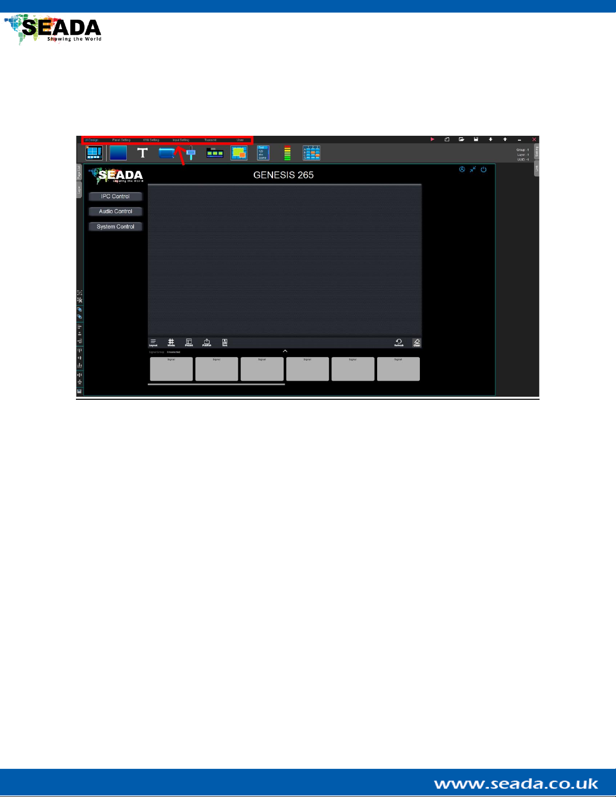
4.2. Designer Menu
This is the main menu of the G265 Designer Software and it contains all the functions supported by the
G265 transceiver.
UI Design: Contain components to build up the User Interface (UI) for the G265 Client.
Panel Setting: Config the output panel and its audio settings.
Input Setting: Scan and manage input signals.
User: User management for the G265 Client.

SD-EN-030 12 / 40 V1.0
4.3. Designer Tool Menu
This menu contains basic functions to operate the designer.
Run test: Enter the test mode to check the UI design of the software, such as page switching and button
binding.
Note that this mode runs offline and is only used to check the UI design, such as page switching and
button binding. Therefore functions that require the connection to the G265 transceiver, such as setting
up the output panel and PTZ IP camera control, cannot be tested under this mode.
Clear then New: Clear the current UI design and create a new one.
Open: Open an existing design.
Save as…: Save the current design into a ‘.txt’file.
Download: Download the design from the connected G265 transceiver.
Upload: Upload the current design to the connected G265 transceiver.
Hide: Hide the Designer software.
Save then Exit: Save the current design and exit the G265 Designer Software.

SD-EN-030 13 / 40 V1.0
4.4. UI Design Area
This is the area where UI components for the G265 Client are created. The layout of the UI in the G265
Client will follow the design in the ‘UI Design Area’. On the top-right of the area, there are three buttons:
‘Logout’, ’Min’ and ’Exit’. They are only accessible in the G265 Client for loging out, minimising and exiting
the G265 Client.

SD-EN-030 14 / 40 V1.0
4.5. UI Tool Menu
This menu contains operations that can be made to the UI components in the ‘UI Design Area’.
Merge: Merge the selected components into one group.
Cancel Group: Cancel the merge of the selected components.
Set Top: Set the selected component to the top.
Set Bottom: Set the selected component to the bottom.
Left Align: Align the selected components to the left.
Horizontal Center: Align the selected components horizontally centred.
Right Align: Align the selected components to the right.
Top Align: Align the selected components to the top.
Vertical Align: Align the selected components vertically centred.
Bottom Align: Align the selected components to the bottom.
Horizontal Array: Symmetrise the selected components horizontally.
Vertical Array: Symmetrise the selected components vertically.
Export: Export the selected component as an ‘.itm’ file and this file can be imported using ‘Open’ in the
‘Designer Tool Menu’.
Note that the above functions can also be executed by right-clicking the components.

SD-EN-030 15 / 40 V1.0
4.6. UI Design –UI Menu
This menu contains components to build up the UI for the G265 Client. Except ‘New Page’, all components
can be ‘dragged&dropped’onto the ‘UI Design Area’ to be created. All the UI components can also be
deleted by clicking ‘Del’ on the keyboard after being selected.

SD-EN-030 16 / 40 V1.0
4.6.1. New Page

SD-EN-030 17 / 40 V1.0
By default, the designer has a global page with one output panel, one input signal group and multiple
function buttons. The function buttons grant user access to a blank page without contents, an IPC control
page for the IPC control, an audio control page to control audio and a system control page with multiple
buttons for further use.
User can switch between different pages by choosing the pages from the ‘Page List’ on the left. By clicking
the ‘New Page’button, user can create a new page in the G265 Client for further use. The created page
can be viewed in the ‘Page List Menu’and the name of it can be changed by double-clicking the page tab
in the page list. In the G265 Client, the pages can be switched either by a ‘Button’or a ‘Page switch list’.
- Page List Menu: Basic operations for the pages created by the ‘UI Menu’.
Move Up: Move the current page up by one.
Move down: Move the current page down by one.
Copy a Page: Copy the current page and paste a new one below it.
Copy to End: Copy the current page and paste a new one at the end of the page list.
Export: Export the current page to a ‘.pag’file and this page can be imported via ‘Open’ in the ‘Designer
Tool Menu’.
Delete Page: Delete the current page.
Note that the global page cannot be deleted.
- Global Setting Menu: Configuration of the G265 Client.
UI Size: Config the window size of the G265 Client.
System: Modify the system buttons ‘Login’, ’Min’ and ’Exit’ and also fonts shown in the G265 Client. The
background picture of the ‘Login Dialog box’ can also be changed in this section.
Fill: Change the colour or background design of the ‘Login Dialog box’.
- Layer: The layer of the components on the current page.
Layer: The colour shows the type of the UI component. The number represents the layer level of the
component and components on the top are assigned with higher numbers.
- Link: Additional functions supported by the component. More details will be given during the
introduction of the UI components and their practical use.
Other manuals for GENESIS 265
1
Table of contents
Other Seada Transceiver manuals

Popular Transceiver manuals by other brands


CYP
CYP COH-TR7 Operation manual

Standard
Standard C58 instruction manual

Alinco
Alinco DJ-S46 specification

Microhard Systems
Microhard Systems MHX2421 operating manual

Kenwood
Kenwood TS-930S instruction manual

Schweitzer Engineering Laboratories
Schweitzer Engineering Laboratories SEL-3022 instruction manual