Baltimore Aircoil Company 3000 Series Manual

Series 3000 and Series 1500
Crossflow Cooling Towers
Table of Contents Page
General Maintenance Information . . . . . . . . . . . . . . 2
Operation and Maintenance . . . . . . . . . . . . . . . . . . 3
Initial and Seasonal Start-Up . . . . . . . . . . . . . . . . 4
Operation . . . . . . . . . . . . . . . . . . . . . . . . . . . . . . . 4
Seasonal Shutdown . . . . . . . . . . . . . . . . . . . . . . . 4
Maintenance Procedures . . . . . . . . . . . . . . . . . . . . 5
BALANCE-CLEAN®
EASY-CLEAN™
Chamber/Inlet Pre-Strainer . . . . . . . . . . . . . . . . . . . 5
Cold Water Basin . . . . . . . . . . . . . . . . . . . . . . . . . 5
Make-Up Valve . . . . . . . . . . . . . . . . . . . . . . . . . . . 6
Fan Motor . . . . . . . . . . . . . . . . . . . . . . . . . . . . . . . 6
BALTIDRIVE®Power
Train Drive System . . . . . . . . . . . . . . . . . . . . . . 6
Fan Shaft Bearings . . . . . . . . . . . . . . . . . . . . . . . . 7
Adjustable Motor Base . . . . . . . . . . . . . . . . . . . . . 7
Corrosion Protection . . . . . . . . . . . . . . . . . . . . . . 8
Winter Operation . . . . . . . . . . . . . . . . . . . . . . . . . . 9
Water Treatment . . . . . . . . . . . . . . . . . . . . . . . . . . 10
Biological Control . . . . . . . . . . . . . . . . . . . . . . . . 11
Factory Authorized Parts . . . . . . . . . . . . . . . . . . . . 12
Baltimore Aircoil Company Crossflow Cooling
Towers have been designed to give long, trouble-
free service when properly installed, operated, and
maintained. To obtain optimum performance and maxi-
mum service life, it is important that a program of regular
inspection and maintenance be developed and carried
out. This bulletin is published as a guide to establishing
such a program.
Included in the bulletin are the recommended services for
start-up, operation, and shutdown and the approximate
frequency for each.
Note that the recommendations on
frequency of service are minimums and where operating
conditions are severe, the services should be performed
more often.
For each required service, follow the proce-
dures outlined under the “Maintenance Procedures”
section of this bulletin. The cooling towers are illustrated
on page 2 with the major points of inspection and service
identified. A copy of the unit certified drawing should also
be available for reference. If you need additional informa-
tion about the operation or maintenance of this equip-
ment that is not covered in this bulletin, contact the local
B.A.C. Representative. Their name and telephone number
are on a label at the connection end of the unit.
BULLETIN M244/1-OAE
Operating and
Maintenance Instructions

2
General
Maintenance
Information
The services required to maintain a cooling tower
are primarily a function of the quality of the air and
water in the locality of the installation:
AIR:
The most harmful atmospheric conditions are those with
unusual quantities of industrial smoke, chemical fumes,
salt or heavy dust. Such airborne impurities are carried
into the cooling tower and absorbed by the recirculating
water to form a corrosive solution.
WATER:
The most harmful conditions develop as water evaporates
from the cooling tower, leaving behind the dissolved solids
originally contained in the make-up water. These dissolved
solids may be either alkaline or acidic and, as they are
concentrated in the circulating water, can produce scaling
or accelerated corrosion.
The extent of impurities in the air and water determines the
frequency of most maintenance services and also governs
the extent of water treatment which can vary from a simple
continuous bleed and biological control to a sophisticated
treatment system. (See “Water Treatment”.)
Figure 1 – Cutaway view of Series 3000 Cooling Tower
Figure 2 – Series 3000 Balance Clean Chamber Figure 3 – Cutaway view of Series 1500 Cooling Tower
Top Water Inlet
Casing
Wet Deck
Surface with
Integral Drift
Eliminators
Make-up Valve
Adjustable Float
Fan
Fan Motor
Fan Deck
Corrosion Resistant Fan
Sheave
Conduit™ Distribution
System Covers
Conduit™ Distribution
System
Air Inlet Louvers
Cold Water Basin Motor
Conduit™ Distribution
System Covers
Conduit™ Distribution
System
Air Inlet Louvers
Make-up Valve
Adjustable Float
Water Outlet
Wet Deck
Surface with
Integral Drift
Eliminators
Suction Strainer
Top Water Inlet
Balance Clean®
Chamber
One Piece Multi-grooved
Banded Belt
Suction Strainer
Water Outlet

Operation and Maintenance
Described below are the recommended services for start-up, operation, and shutdown and the approximate
frequency for each.
3
Type of Service Monthly Quarterly Start-Up Shutdown Annually Ref. Page
Inspect General Condition of Tower
Inspect and Clean as Necessary:
A1) Optional BALANCE–CLEAN®
Chamber Inlet Strainer*
A2) Optional EASY CLEAN™
Chamber Inlet Strainer**
B) Cold Water Basin
C) CONDUIT™ Distribution System
D) Air Inlet Louvers
Check and Adjust Water Level in:
Cold Water Basin
Check Operation of Make-Up Valve
Check Bleed Rate and Adjust
BALTIDRIVE Power Train:
A) Check Condition of Belt
B) Readjust Tension on Belt
Lubricate Fan Shaft Bearings
Lubricate Motor Base Adjusting Screw
Clean Outside of Fan Motor
Inspect Protective Finish
XX
XXX
XXX
XXX
XXX
XX
XX
XX
7 & 8
XX 7
X7&8
XXX
X
X
X
TABLE 1: Recommended Maintenance Services for Series 3000, and Series 1500 Cooling Towers
WARRANTIES: Please refer to the Limitation of Warranties applicable to and in effect at the time of sale/purchase of these products.
Freeze Protection: These products must be protected by mechanical and operational methods against damage and/or reduced effectiveness due to
possible freeze-up. Please refer to the Product catalog or contact the local B.A.C. Representative for recommended protection alternatives.
WARNING: Before performing any maintenance or inspection, make certain that all power has been disconnected
and locked in the off position
NOTES:
1. Recommended service
intervals are for typical
installations. Severe
environment conditions
may dictate more
frequent servicing.
2. When operating in
ambient temperatures
below freezing, the
cooling tower should be
inspected more
frequently (see Winter
Operation, page 9).
3. Tension on new belts
must be readjusted
after first 24 hours of
operation and quarterly
thereafter.
* Series 3000
** Series 1500
SAFETY PRECAUTIONS:
The operation, maintenance, repair of this equipment should be
undertaken only by qualified personnel. All qualified personnel
should be thoroughly familiar with the equipment, the associated
system and controls, and the procedures set forth in this manual.
Proper care, procedures, and tools must be used in handling, lifting,
installing, operating, maintaining and repairing this equipment to
prevent personal injury and/or property damage.
All electrical, mechanical, and rotating machinery constitute a
potential hazard, particularly for those not familiar with the design,
construction, and operation. Accordingly, adequate safeguards
(including the use of protective enclosures where necessary) should
be taken with this equipment both to safeguard the public (including
minors) from injury and to prevent damage to the equipment, its
associated system, and the premises.
The cooling towers are designed so that access to the top of the
cooling tower is not required to perform routine maintenance. The
top horizontal surface of the tower is not intended for use as a
walking surface or working platform. Service of the CONDUIT™
Distribution System can be accomplished with a portable ladder
from the side or louver face of each cell. If access to the top of the
unit is desired, the purchaser/end-user is cautioned to use appropri-
ate means, complying with applicable safety standards of govern-
mental authorities. At no time should this equipment be operated
without all fan screens, access panels, and access doors in place.
WARNING: When the fan speed of the cooling tower is changed
from the factory set speed, including changes achieved by the use
of a variable fan speed control device, steps must be taken to avoid
operating at or near the fan’s “critical speed” which could result in
fan failure and possible injury or damage. Consult with your local
B.A.C. Representative on any such applications.
WARNING: For the protection of authorized service and mainte-
nance personnel, each fan and pump motor associated with this
equipment should be installed with a lockable disconnect switch
located within sight of the cooling tower. No service work should be
performed on or near the fans, motors, and drives or inside the unit
without first ensuring the fan and pump motors have been discon-
nected and locked out.
WARNING: The recirculating water system may contain chemicals
or biological contaminants, including Legionella, which could be
harmful if inhaled or ingested. Accordingly, personnel who may be
exposed directly to the discharge airstream and the associated drift,
mists generated during operation of the water distribution system
and/or fans, or mists produced by high pressure water jets or com-
pressed air (should these be used to clean portions or components
of the recirculating water system), should wear respiratory protec-
tion equipment approved for such use by OSHA and/or local
occupational safety and health authorities.

4
Operation and
Maintenance
INITIAL AND SEASONAL START-UP:
Prior to initial start-up or after a shut down period, the
cooling tower must be thoroughly inspected and cleaned:
1. Clean all debris, such as leaves and dirt, from inside the
tower, and the air inlet louvers.
2. Cooling Towers equipped with the optional BALANCE-
CLEAN®or EASY CLEAN™ Chambers should remove the
inlet strainer, clean and reinstall.
3. Drain the cold water basin (with basin strainers in place)
and flush to remove accumulated dirt.
4. Remove the suction strainer, clean and reinstall.
5. Turn the fan(s) by hand to insure rotation without
obstruction.
6. Start the fan motor(s) and check for proper fan rotation.
7. At seasonal start-up, adjust the belt tension on the
BALTIDRIVE®PowerTrain fan drive system. Note that at
initial start-up the tension need not be adjusted since the
drive has been properly tensioned at the factory prior to
shipment.
8. Check float operated make-up valve to be sure it is
operating freely.
9. Prior to seasonal start-up, lubricate the fan shaft
bearings. Note this is not required at initial start-up since
the fan bearings have been lubricated at the factory prior
to shipment.
10. At initial start-up or before start-up when the cold-
water sump is completely drained, fill the cold-water sump
with fresh water to the overflow level. For new installations,
initiate the biocide water treatment program at this time
(see Water Treatment Section). At seasonal start-up, and
following a shutdown period of more than 3 days, resume
the biocide treatment program or administer a shock treat-
ment of appropriate biocides prior to operating the cooling
tower fans to eliminate accumulated biological contami-
nants (see Biological Control Section).
11. Set the float on the make-up valve to shut off the valve
when the float is approximately 1/2" below the overflow
level.
12. For Series 3000 Cooling Towers, balance flow to the
CONDUIT™ Distribution System by adjusting the flow
balancing valves (by others or optionally supplied by
B.A.C.). Adjustment to the balancing valves is not required
if the unit is equipped with the optional BALANCE-CLEAN®
Chamber and EASY CONNECT®Piping Arrangement.
Multi-cell arrangements will require flow balancing
between cells to obtain even water distribution.
13. Open the valve in the tower bleed line (by others) and
adjust bleed to the recommended rate. (See “Water
Treatment”– page 10.)
(continued)
14. Check the voltage and current of all three legs of the
fan motor. The current should not exceed the nameplate
rating. Note: Current should be measured during warm
ambient conditions and with a heat load on the tower. After
prolonged shutdowns, the motor insulation should
be checked with a “megger” insulation tester prior to
restarting the motor.
CAUTION: Rapid on-off cycling can cause the fan motor
to overheat. It is recommended that the controls be set to
allow a maximum of 6 on-off cycles per hour.
When using a 2-speed motor, the starter should include a
15-second time delay when switching from high speed to
low speed.
Inverter Duty Fan Motors, furnished in accordance with
NEMA Standard MG.1 Part 31 are recommended for
applications using Variable Frequency Drives for fan
motor control.
AFTER 24 HOURS:
After 24 hours of operating under load, the following
services should be performed:
1. Check the tower for any unusual noise or vibration.
2. Check the operating water level in the cold water basin.
Adjust make-up float valve if necessary.
3. Readjust the belt tension.
OPERATION:
During operation, the tower should be inspected, cleaned,
and lubricated on a regular basis. The required services
and recommended frequency for each are summarized in
Table 1 on page 3 of this bulletin.
SEASONAL SHUTDOWN:
The following services should be performed whenever the
cooling tower is to be shutdown for more than 3 days:
1. Drain the cold water basin and all piping that will be
exposed to freezing temperatures.
2. Clean and flush the CONDUIT™ Distribution System
and cold water basin with the basin strainers in place.
Leave the cold water basin drain open so rain and melting
snow will drain from the tower (for Series 3000 units with
the optional BALANCE-CLEAN®Chamber and Series 1500
units with the optional EASY-CLEAN™ Chamber, clean and
flush the inlet strainer).
3. Clean the basin strainers and reinstall.
4. Cover the fan discharge opening to keep out dirt
and debris.
5. Lubricate the fan shaft bearings and motor base
adjusting screw.
6. Close the shutoff valve in the make-up water line (by
others) and drain all exposed make-up water piping.
7. Inspect the integrity of the corrosion protection system
on the steel portion of the tower. (See Corrosion
Protection, page 8.)

5
CONDUIT™ DISTRIBUTION SYSTEM:
The CONDUIT™ Distribution System must be kept clean
to provide design flow. Check to see if the nozzles are
producing uniform water distribution over the wet deck
surface (Figure 2). When maintenance is required the
conduit assembly can be removed for ease of cleaning.
Simply unscrew the conduit assembly by turning it
counter-clockwise, approximately 3 turns. Clean the
conduit of loose debris and remove any deposits. Clean
any clogged nozzles. If necessary, the nozzle and rubber
grommet can be removed for cleaning. Remove any dirt
or debris that may clog the conduits/nozzles quarterly.
OPTIONAL BALANCE-CLEAN®CHAMBER:
(Balance Clean®Chamber – Series 3000 Cooling Towers Only)
The water to be cooled enters the tower through a single
connection and passes through the BALANCE-CLEAN®
Chamber. The device is equipped with an internal strainer.
Located at the bottom of the BALANCE-CLEAN®
Chamber is a capped cleanout connection. This can be
used to periodically purge the BALANCE-CLEAN®
Chamber of dirt and debris collected by the strainer.
The strainer should be cleaned periodically as shown
in the Recommended Maintenance Schedule. This is
accomplished by un-bolting and temporarily removing
the chamber bottom plate and inspecting the strainer for
dirt and debris.
OPTIONAL EASY-CLEAN™ CHAMBER:
(EASY-CLEAN™ Chamber – Series 1500 Cooling Towers Only)
The water to be cooled enters the tower through a single
connection and passes through the EASY-CLEAN™
Maintenance
Procedures
Chamber. The device is equipped with an internal strainer.
Located at the bottom of the EASY-CLEAN™ Chamber is
a capped clean-out connection. This can be used to
periodically purge the EASY-CLEAN™ Chamber of dirt and
debris collected by the strainer. The strainer should be
cleaned periodically as shown in the Recommended
Maintenance Schedule. This is accomplished by un-
bolting and temporarily removing the chamber bottom
plate and inspecting the strainer for dirt and debris.
COLD WATER BASIN AND SUCTION STRAINERS:
As the water circulating though the tower is cooled, it
collects in the cold water basin and passes through the
strainers into the system. The operating water level is
controlled by the make-up valve and should be maintained
at the operating water level shown in Table 2.
The operating water level in the cold-water basin will vary
somewhat with system thermal load (evaporation rate),
the bleed rate employed and the make-up water supply
pressure. Because the typical winter load is less than the
summer load, the winter evaporation rate is frequently
less than the summer evaporation rate. With this reduced
evaporation rate in winter, the water level in the cold water
basin will increase unless the float is re-adjusted. The
operating water level should be checked monthly and
the float re-adjusted as necessary to maintain the
recommended operating level.
The water level in the basin of equipment designed for
remote sump operation is a function of the circulating
water flow rate, water outlet connection size, quantity and
location, and outlet piping size and configuration. The
remote sump unit is supplied without a water make-up
assembly and the sump operating level during operation
is not adjustable.
The cold water basin should be inspected regularly. Any
trash or debris which may have accumulated in the basin or
on the strainers should be removed and, if necessary, the
float adjusted to maintain the design operating level.
Conduit™ Distribution System
Figure 2
Optional Balance Clean Chamber
Figure 3

6
Maintenance
Procedures
Quarterly, or more often if necessary, the entire cold-
water basin should be drained, cleaned, and flushed with
fresh water to remove the silt and sediment which
normally collects in the basin.
It is important to note that although stainless steel and
BALTIBOND®Corrosion Protection System — protected
basins provide added protection from corrosion, the
same maintenance applies to them as well.
If not removed periodically, this sediment can become
corrosive and cause deterioration of the protective finish
of metallic basins. When flushing the basin, the strainers
should be left in place to prevent the sediment from re-
entering the tower system. After the basin has been
flushed, the strainers should be removed, cleaned, and
replaced before refilling the basin with fresh water.
WARNING: Openings and/or submerged obstructions
may exist in the bottom of the cold-water basin. Use
caution when walking inside this equipment.
MAKE-UP VALVE:
A float operated mechanical water make-up assembly is
furnished as standard equipment on the cooling tower
(unless the unit has been ordered with the optional
electric water level control package or for remote sump
application). It is located inside the unit cold water basin
within easy reach from the access door at the connection
end of the unit on the Series 3000 and Series 1500
Cooling Towers.
The standard make-up assembly consists of a bronze
make-up valve connected to a float arm assembly and
actuated by a large diameter polystyrene filled plastic
float. The float is mounted on an all-thread rod which is
held in place by wing nuts. The operating water level in
the cold water basin can be adjusted by repositioning the
float and all-thread rod using the wing nuts provided.
The make-up assembly should be inspected monthly
and adjusted as necessary. The valve itself should be
inspected annually for leakage and the valve seat
replaced if necessary. The make-up water supply
pressure should be maintained between 15 and 50
psig for proper operation of the valve.
To set the initial basin water level, adjust the wing nuts so
that the make-up valve is completely closed when the
water level in the cold water basin is 1/2" below the
overflow connection. Under design thermal load and with
average city water pressure (15 to 50 psig) at the valve,
this setting should produce the operating water levels
stated in Table 2. Note that if the thermal load is less than
the design load at the time of unit start-up, the procedure
may produce operating levels greater than that shown. It
may be necessary to re-adjust the float in order to attain
the recommended operating level. The unit basin should
be closely monitored and water level adjusted as
necessary during the first 24 hours of operation.
As an option, an electric water level control package is
available in lieu of the above described mechanical
make-up assembly. The package consists of a probe-
type liquid level control assembly and a slow-closing
solenoid valve. Stainless steel electrodes, factory-set at
predetermined lengths, extend from an electrode holder
into the cold-water basin. These electrodes should be
periodically cleaned to prevent accumulations of
scale, corrosion, sludge or biological growth from
interfering with the electrical circuit. With the electric
water level control package, the water level is maintained
at the recommended operating level regardless of the
system thermal load. Therefore, it is not necessary, nor is
it recommended that the operating level be adjusted.
During the start-up of units equipped with the electric
water level control package, the control unit should be
bypassed in order to fill the unit 1/2" below the overflow
connection.
Operation at the recommended water level will ensure
that the unit basin contains sufficient water volume to
prevent air entrainment in the circulating pump during
system start-up and to provide sufficient excess basin
capacity to accept the total system pull-down volume.
(“Pull-down volume” is defined as that quantity of water
suspended in the tower during pump operation plus that
contained in the water distribution system, external piping,
and any heat exchangers which could drain to the tower
cold water basin when the circulating pump is shut down.)
FAN MOTOR:
The standard fan motor used on Series 3000 and Series
1500 Cooling Towers is a T.E.A.O. motor (Totally
Enclosed, Air Over) with permanently lubricated ball
bearings and special moisture protection on the bearings,
shaft, and windings. The only servicing required during
operation is to clean the outside surface of the motor at
least quarterly to insure proper motor cooling. Additionally,
after prolonged shutdowns, the motor insulation be
checked with a “megger” insulation tester prior to
restarting the motor.
(continued)(continued)
Height of Water in
Model No. the Cold Water Basin
(in.)
Series 3000 Models
33245 to 33501 83⁄4"
Series 3000 Models
33522 to 331328 93⁄4"
All Series 1500 Models 83⁄4"
TABLE 2. Cold Water Basin Operating Water Level

7
Maintenance
Procedures
FAN SHAFT BEARINGS:
The fan shaft is supported by two pillow block ball
bearings, each equipped with a lubrication fitting and a
slinger/locking collar to keep out moisture. The bearings
should be lubricated as follows:
Initial Start-Up: Normally no lubrication is required since
the bearings have been lubricated at the factory prior to
shipment. However, if the cooling towers have been stored
at the job site for more than one year, bearings should be
lubricated with new grease before initial operation. When
lubricating, purge the old grease from the bearing by
gradually adding grease until a bead of new grease
appears at the seal on the underside of the bearing.
Seasonal Start-Up: Purge both bearings with new
grease prior to start-up.
Operation: Lubricate bearings after every 2,000 hours of
operation or once every three months, whichever comes
first.
Seasonal Shutdown: Purge bearings with new grease
prior to any prolonged storage or downtime.
The fan shaft bearing should be lubricated only with a
hand grease gun. Do not use high pressure grease
guns since they may rupture the bearing seals.
Lubricate the bearings only with one of the following
water resistant greases which are good for ambient
temperatures ranging from –65˚F to +250˚F.
American – Rycon #3
Keystone – 84 EP Light
Exxon – Beacon #325
Mobil – Mobil #28
Shell – Aeroshell #17
Chevron – SRI
ADJUSTABLE MOTOR BASE:
The motor base adjusting screw (See figure 4 & 5) should
be coated twice a year using a good quality corrosion
inhibiting grease such as one of those recommended for
lubricating the fan shaft bearings.
BALTIDRIVE®POWER TRAIN:
The BALTIDRIVE®Power Train consists of a specially
designed belt, with corrosion-resistant fan motor sheaves.
The solid-backed, multi-groove, neoprene/polyester belt
provides the premium quality necessary for cooling tower
service. The corrosion-resistant sheaves extend the life of
the belt by minimizing any possibility of rust or corrosion.
These components provide a highly reliable system with
low-maintenance requirements. The only servicing
required on the BALTIDRIVE®Power Train is to periodi-
cally check the condition of the belt and, when neces-
sary, adjust the tension. The recommended service
intervals are specified below:
INITIAL START-UP:
No servicing is required prior to initial tower start-up since
the drive has been tensioned and aligned at the factory.
SEASONAL START-UP:
Readjust the tension on the belt.
OPERATION:
After the initial tower start-up or the installation of a
new belt, the tension must be readjusted after the first
24 hours of operation. Thereafter, the condition of the
belt should be checked quarterly and the tension adjust-
ed as necessary, but at least once every three months.
To check the belt tension, place a straight edge along the
belt from sheave to sheave as shown in Figure 6a or use
a tape measure as shown in Figure 6b to measure belt
deflection. Apply a moderate force by hand (approximately
40 lbs) evenly across the width of the belt in the center of
the span between the sheaves. If the belt deflects between
1/4" and 3/8" as shown in Figure 6a and 6b, the belt is
adequately tensioned.
(continued)
Adjustable Motor Base – Series 3000 and
Figure 5
Adjustable Motor Base — Series 1500
Figure 4

8
If belt tensioning is required, proceed as follows:
1. Loosen the lock nut on the Motor Base Adjusting
Screw (see Figure 4 & 5).
2. Turn the Motor Base Adjusting Screw clockwise to
tension the belt, or counterclockwise to relieve belt
tension. During adjustment of belt tension, the drives
should be rotated several times by hand to evenly
distribute the tension throughout the belt.
3. When the belt is properly tensioned, retighten the
locking nut on the Motor Base Adjusting Screw.
NOTE: There should be no “chirp” or “squeal” when the
fan motor is started.
The drive alignment should be checked annually to
ensure maximum belt life. This can be done by placing
a straight edge across the driver and driven sheaves as
shown in Figure 7a for standard drives and in Figure 7b
for ENERGY-MISER®Fan System drives. When the drives
are properly aligned, the straight edge will contact all four
points as indicated. There should be no more than 1/16"
deviation from four point contact. If realignment is neces-
sary, loosen the motor sheave and align it with the fan
sheave. Allow approximately 1/4" for draw-up as the
bushing screw is retightened.
Figure 6b
Figure 7a — Standard Drives
Figure 7b — ENERGY-MISER®Fan System Drives
Corrosion Protection
The Series 3000 and Series 1500 Cooling Towers are con-
structed of corrosion-resistant materials. The wet deck sur-
face is made of an inert synthetic material, which requires
no protection against rot, decay, rust or biological attack.
Other materials used in construction of the equipment,
which are listed below, should be inspected regularly.
Galvanized steel components
Galvanized steel components should be inspected for
blemishes or corrosion. Affected areas should be wire
brushed and recoated with a cold galvanizing compound
such as ZRC.
BALTIBOND®Corrosion Protection System
Components
Galvanized steel components protected with the
BALTIBOND®Corrosion Protection System may develop
scratches, scrapes or blemishes. These may be touched
up with a repair kit (B.A.C. Part No. 16-133P). In the
unlikely event that the damage is more extensive than
simple scratches or minor blemishes, contact your local
B.A.C. Representative.
Stainless Steel Components
Stainless steel components should be inspected for signs
of blemishes or corrosion and cleaned with stainless steel
wool as necessary. If more extensive corrosion is preva-
lent, contact your local B.A.C. Representative.
Fiberglass Re-Inforced Polyester (FRP) Components
Series 3000 and Series 1500 Cooling Towers are provided
with FRP casing panels and air inlet louvers as standard.
These components should be inspected for accumulation
of dirt and cleaned with soap and water as necessary.

9
Winter Operation
The Series 3000 and Series 1500 Cooling Towers
can be operated at ambient temperatures below
freezing provided proper operating methods are
established and diligently followed. Precautions that must
be taken to insure satisfactory operation include:
• Freeze protection of the water in the cold water basin
when tower is idle.
• Elimination of water in the optional BALANCE CLEAN®
Chamber and internal piping (Series 3000 only) when
the tower is idle.
• Elimination of water in the optional EASY CLEAN®
Chamber and internal piping (Series 1500 only) when
the tower is idle.
• Control of ice formation during tower operation.
Freeze protection must be provided for the cold water
basin during shutdown since ice formation in the basin
can severely damage the cooling tower. A remote sump
located indoors in a heated space is an ideal method
since the water in the tower and connecting piping will
drain by gravity whenever the circulating pump is
stopped. Where a remote sump arrangement is
impractical, a form of cold water basin heat must be
provided in the tower itself. Electric immersion heaters
or steam coils, controlled by a thermostat in the cold
water basin, may be used. Consult your B.A.C.
Representative for details. Additionally, where a remote
sump is not used, all exposed make-up lines and
water piping that does not drain at shutdown should
be traced with electric heater tape and insulated.
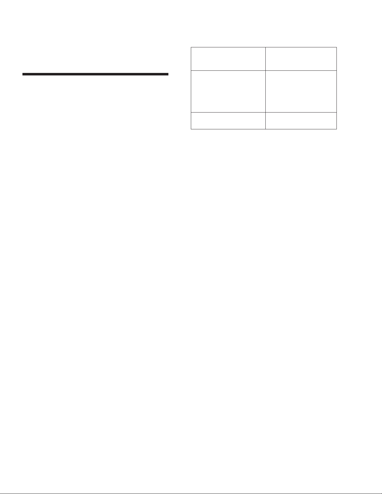
Series 3000 Cooling Towers with Optional BALANCE-
CLEAN® Chamber or Series 1500 Cooling Towers with
Optional EASY-CLEAN™ Chamber
Draining the water from the BALANCE CLEAN®or
EASY-CLEAN™ Chambers and internal piping is essential
whenever the potential for freezing temperatures exist.
This can be accomplished by utilizing the 1/2" NPT port
drain located on the inboard side of the BALANCE
CLEAN®or EASY-CLEAN™ Chamber. There are 3
recommended methods for draining the piping:
1. The preferred approach is to install a normally open
1/2" solenoid valve on the 1/2" drain connection of the
BALANCE CLEAN®or EASY-CLEAN™ Chamber. This
valve should be wired in the pump circuit such that it
closes when the pump is energized. The solenoid valve
must be selected to operate with a minimum pressure
differential of zero psi. The zero pressure differential valve
is required due to the limited static head imposed on the
valve from the water column.
or
2. A 1/2" manual valve can be installed on the 1/2" drain
connection of the BALANCE CLEAN®or EASY-CLEAN™
Chamber. The valve should be opened during cold
weather operation. CAUTION: The valve must be closed
during warm weather to obtain full thermal performance.
or
3. Remove the 1/2" plug from the 1/2" drain connection of
the BALANCE CLEAN®or EASY-CLEAN™ Chamber during
cold weather operation. CAUTION: The plug must be
reinstalled during warm weather to obtain full thermal
performance.
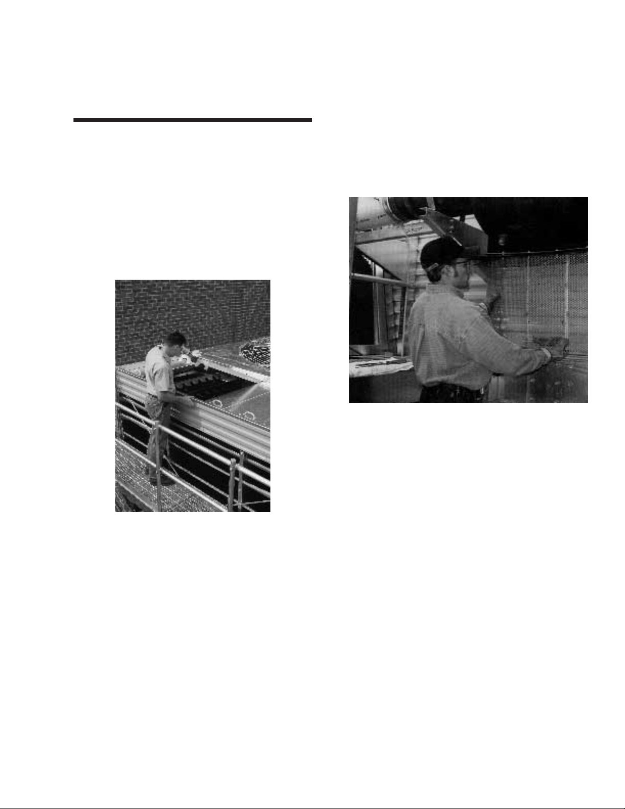
When the cooling tower is operated at wet bulb tempera-
tures below freezing, ice may form on wetted areas in
direct contact with the incoming air. Therefore, the inlet
louvers and outer face of the wet deck surface must be
inspected frequently so that if icing occurs, steps can be
taken to remove the ice before the tower is damaged or
system performance impaired.
When operating at subfreezing ambient temperatures, the
cooling tower will normally produce leaving water temper-
atures appreciably below design. However, low leaving-
water temperatures tend to promote ice formation.
Therefore, when operating in subfreezing ambient
temperatures, the leaving water temperatures should
be maintained as high as possible. The recommended
minimum water temperature in the cold water basin is
43˚F. Additionally, frequent visual inspections should
be performed to detect potential icing problems.
The first step in maintaining a high leaving water tempera-
ture is to ensure the tower operates with the maximum
possible heat load. Next, reduce the tower capacity by
cycling fans. Modulating the water flow rate to the tower is
not recommended as a method for cooling tower capacity
control. (CAUTION: Rapid on-off cycling can cause the
fan motor to overheat. It is recommended that controls
be set to allow a maximum of 6 on-off cycles per hour.)
If the tower is equipped with two-speed motors, operation
at low speed may be sufficient to prevent icing.
(Note: When two speed motors are used, the motor
starter should include a 15 second time delay when
switching from high to low speed.) However, it may also
be necessary to cycle fans off periodically to prevent ice
formation and/or to melt ice that accumulates on the
intake louvers and face of the wet deck surface. Again, it is
recommended that the controls be set to allow a
maximum of 6 on-off cycles per hour.
Under severe conditions where fan cycling is insufficient to
prevent icing, it may be necessary to operate the fan(s) in
reverse to remove any ice accumulation by forcing warm
air out to the intake louvers. WARNING: At such times,
DO NOT operate the fans in reverse any longer than is
necessary since extended reverse operation may
cause ice to form on the fan blades, fan stack, or elimi-
nators and damage the tower. Because of this possibility,
cooling towers using reverse fan operation for ice removal
should be equipped with a vibration cutout switch and
the duration of reverse operation should be limited to a
maximum of thirty minutes. A time delay of approximately
40 seconds between forward and reverse direction should
be incorporated into the motor controls.
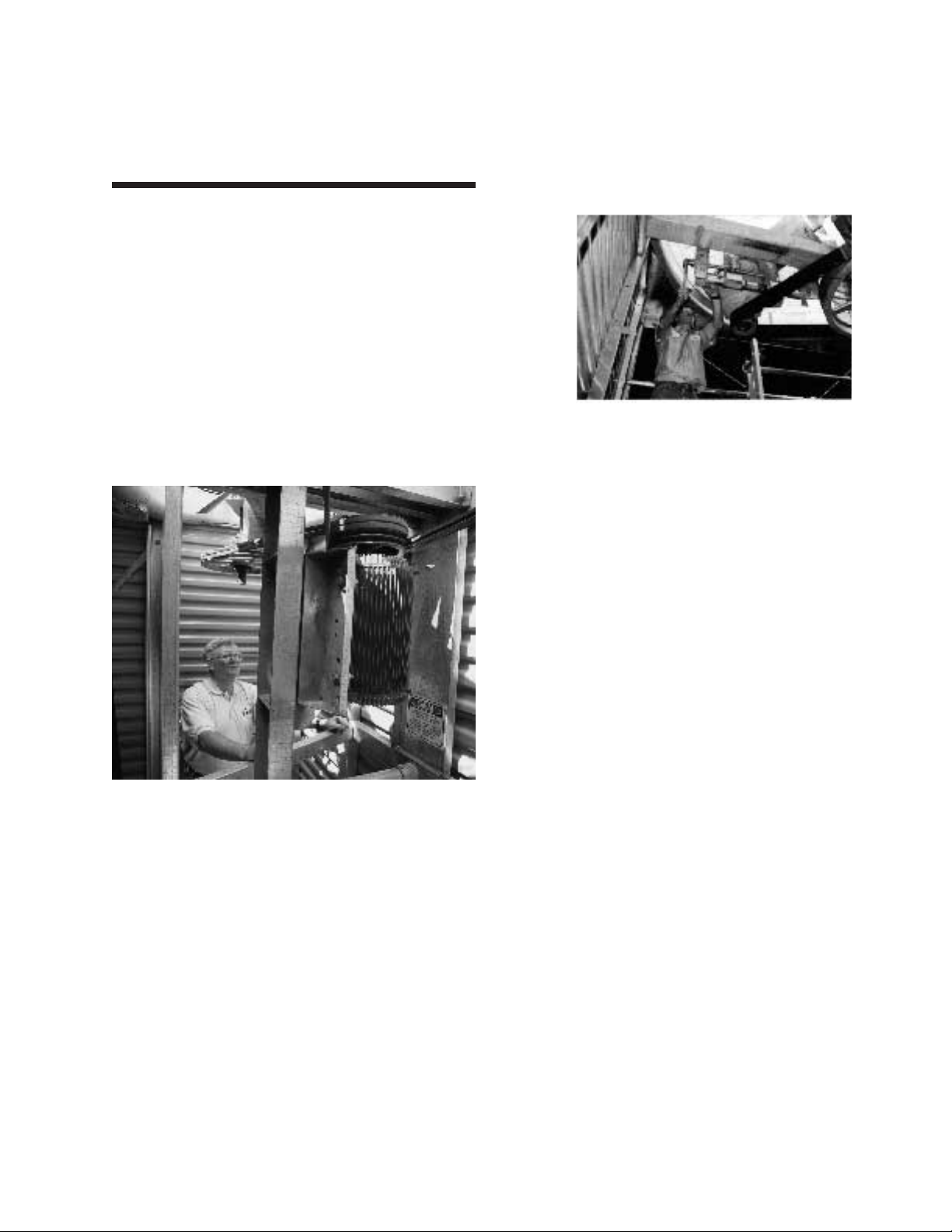
Lastly, the importance of performing frequent visual
inspections and routine maintenance services during oper-
ation in subfreezing weather cannot be overemphasized.
These must be carried out on a routine basis to:

10
1. Ensure all controls for capacity and freeze protection
are set properly and functioning normally.
2. Prevent excessively high water levels and possible
overflow of the cold water basin due to over pumping,
clogged strainers, or make-up valve malfunction.
Re-circulated Water Quality Guideline,
1Units manufactured in Canada will be constructed of the
metric equivalent Z700 galvanized steel.
2Units having galvanized steel construction and a
circulating water pH of 8.3 or higher will require periodic
passivazation of the galvanized steel to prevent ‘white
rust’, the accumulation of white, waxy, non-protective zinc
corrosion products on galvanized steel surfaces.
In order to control the cycles of concentration such that
the above guidelines are maintained, it will be necessary
to “bleed” or “blowdown” a small amount of re-circulating
water from the system. This “bleed” water is replenished
with fresh make-up water, thereby limiting the build-up of
impurities.
Typically the bleed is accomplished automatically through
a solenoid valve controlled by a conductivity meter. The
conductivity meter set point is the water conductivity at
the desired cycles of concentration and should be deter-
mined by a competent water treatment expert. (Note: The
solenoid valve and conductivity meter must be supplied
by other vendors) Alternatively, a bleed line with a valve
can be used to continuously bleed from the system.
(Note: The bleed line and valve must be supplied by
other vendors) In this arrangement, the rate of bleed can
be adjusted using the valve in the bleed line and mea-
sured by filling a container of known volume while noting
the time period. The bleed rate and water quality
should be periodically checked to ensure that ade-
quate control of the water quality is being maintained.
The required continuous bleed rate may be calculated by
the formula:
Bleed Rate = Evaporation Rate/Number of Cycles of
Concentration –1
The evaporation rate can be determined by one of the
following:
The evaporation rate is approximately 2 GPM per 1
million BTU/HR of heat rejection.
The evaporation rate is approximately 3 GPM per 100
tons of refrigeration.
Evaporation Rate = Water Flow Rate x Range x .001
Example: At a flow rate of 900 GPM and a cooling
range of 10˚F, the evaporation rate is 9 GPM
(900 GPM x 10˚F x .001 = 9 GPM).
If the site conditions are such that constant bleed-off will
not control scale or corrosion and maintain the water
quality within the guidelines, chemical treatment may be
necessary. If a chemical treatment program is used, it
must meet the following requirements:
3. Discover any icing conditions that may develop before
they reach the point where the tower or supports are
damaged or system performance is impaired.
For more detailed information on winter operation and for
recommended operating procedures on specific installa-
tion, contact your local B.A.C. Representative.
Water Treatment
Corrosion and Scale Control
In cooling towers, cooling is accomplished by the evapor-
ation of a portion of the process water as it flows through
the tower. As this water evaporates, the impurities originally
present remain in the re-circulating water. The concen-
tration of the dissolved solids increases rapidly and can
reach unacceptable levels. In addition, airborne impurities
are often introduced into the re-circulating water, intensi-
fying the problem. If these impurities and contaminants
are not effectively controlled, they can cause scaling,
corrosion, and sludge accumulations which reduce heat
transfer efficiency and increase system operating costs.
The degree to which dissolved solids and other impurities
build up in the re-circulating water may be defined as the
cycles of concentration. Specifically, cycles of concentra-
tion is the ratio of dissolved solids (for example – Totally
Dissolved Solids (TDS), chlorides, and sulfates) in the re-
circulating water to dissolved solids in the make-up water.
For optimal heat transfer efficiency and maximum
equipment life, the cycles of concentration should be
controlled such that the re-circulating water is main-
tained within the guideline list below.
Stainless Steel or
Baltibond®G235
Corrosion Galvanized
Protection System Steel1
pH 6.5 to 9.0 7.30 to 9.02
Hardness as 30 to 500 ppm 30 to 500 ppm
CaCO3
Alkalinity as 500 ppm max. 500 ppm max.
CaCO3
Total
Dissolved 1200 ppm max. 1000 ppm max.
Solids
Chlorides 250 ppm max. 125 ppm max.
Sulfates 250 ppm max. 125 ppm max.

11
1. The chemicals must be compatible with the unit
construction (zinc coated) steel as well as all other
materials used in the system (pipe, heat exchanger, etc.)
2. Chemicals to inhibit scale and corrosion should be
added to the re-circulating water by an automatic feed
system on a continuously metered basis. This will pre-
vent localized high concentrations of chemicals, which
may cause corrosion. It is recommended the chemicals
be fed into the system at the discharge of the
1. Resume treatment with the biocide, which had been
used prior to shutdown. Maintain the maximum recom-
mended biocide residual (for the specific biocide) for a
sufficient period of time (residual and time will vary with
the biocide) as recommended by the water treatment sup-
plier to bring the system under good biological control.
2. Check the pH of the circulating water and, if necessary,
adjust it to 7.0 to 7.6. Then treat the system with sodium
hypochlorite to maintain a level of 4 to 5 mg/l (ppm) free
chlorine over a six (6) hour period. Test kits that can be
used to measure the free residual of chlorine are commer-
cially available.
When it is not practical to drain the system during shut-
down periods, a by-pass line with shut-off valves should
be installed to permit the cooling water to be circulated
throughout the system, including the tower basin, while
by-passing the tower fill. Then, after each shut-down of
three (3) days or more, the system should be treated prior
to restarting the tower using one of the two methods
described above. However, while circulating the treated
cooling tower water through the entire system, the
cooling tower fill should be by-passed and the tower
fans kept inoperative. After the biocide residual has been
maintained at the required level for at least six (6) hours,
the water can be directed over the fill and the tower
returned to service. The standard water treatment program
(including the biological treatment) should be resumed at
this time.
For specific recommendations on treatment for scale,
corrosion, or biological control, consult a qualified
water treatment consultant.
re-circulating pump. They should not be batch fed
directly into the cold water basin.
3. Acid water treatment is
not
recommended unless
the unit(s) have been furnished with the BALTIBOND®
Corrosion Protection System or is constructed of
stainless steel — in which cases acid treatment can be
used provided the requirements of paragraph 1 and 2
above are maintained.
Biological Control
Bleed-off with or without chemical treatment for scale and
corrosion control is not adequate for control of biological
contamination. The growth of algaes, slimes and other
micro-organisms, if unchecked, will reduce system effi-
ciency and may contribute to the growth of potentially
harmful micro-organisms, including Legionella, in the
recirculating water system.
Accordingly, a biocide treatment program specifically
designed to address biological control should be initiated
when the system is first filled with water and administered
on a regular basis thereafter in accordance with the sup-
plier’s instructions. Liquid biocides may be added to the
basin of the cooling tower in dilute form. If a solid form of
biocide is used, it should be added to the system via a
pot feeder. If ozone water treatment is used, ozone
concentrations should not exceed 0.1–0.5 ppm in
order to ensure maximum equipment life.
B.A.C. offers a simple, easily applied, low maintenance
form of biological control, the IOBIO®Bacteria, Slime and
Algae Control. The control is easy to use and requires
little maintenance. By delivering low concentrations of
iodine through the make-up water line, the IOBIO®
Control automatically controls unwanted microbiological
contaminants in the open wet system. Contact your local
B.A.C. Representative for more information.
Start-up Following a Shut-Down Period
To minimize the risk from biological contamination fol-
lowing a shut-down period, it is strongly recommend-
ed that the entire system (cooling tower, system pip-
ing, heat exchangers, etc.) be drained when the sys-
tem is to be shutdown for more than 3 days. To
resume operation of a drained system, clean all debris,
such as leaves and dirt from the cooling tower and re-fill
the system with fresh water. While operating the circulat-
ing pump(s) and prior to operating the cooling tower
fans, execute one of the following two alternative biocide
treatment programs:

12
Offices Worldwide:
Baltimore, USA, Baltimore Aircoil, 1-410/799-6200, FAX: 1-410/799-6416
California, USA, Baltimore Aircoil, 1-559/673-9231, FAX: 1-559/673-5095
Delaware, USA, Baltimore Aircoil, 1-302/422-3061, FAX: 1-302/422-9296
Illinois, USA, Baltimore Aircoil, 1-217/379-2311, FAX: 1-217/379-3522
Georgetown, Canada: Baltimore Aircoil of Canada, 1-905/877-5272, FAX: 1-905/877-9400
Gosford, N.S.W., Australia: Baltimore Aircoil (Australia) Pty., Ltd., (61)(24)3401-200, FAX: (61)(24)3401-545
Heist-op-den Berg, Belgium: Baltimore Aircoil International, (32)(15)257-700, FAX: (32)(15)244-779
Corby, Northants, England: Baltimore Aircoil Ltd., (44)(1536)200-312, FAX: (44)(1536)265-793
Sondrio, Italy: Baltimore Aircoil Italia S.R.L., (39)(0342)482-882, FAX: (39)(0342)483-022
Capetown, Republic of South Africa: Baltimore Aircoil Company, S.A. (Pty) Ltd., (27)(21)371-7121, FAX: (27)(21)(374-2081
Madrid, Spain: BAC Iberica, S.A., (34)(91)302-1732, FAX: (34)(1)302-2831
Joint Ventures:
Dalia, China: Dailian Bingshan Baltimore Aircoil Refrigeration Company, Ltd., (86)(411)469-4854, FAX: (86)(411)(469-4844
Tokyo/Osaka, Japan: BAC Japan Co., Ltd., (81)(3)5450-6161, FAX: (81)(3)5450-6166
Penang, Malaysia: BAC Cooling Towers SDN BHD, (60)(4)507-8822, FAX: (60)(4)507-6272
Licensees:
Sau Paulo, Brazil: Semco Equipamento Industrias Ltda., (55)(11)5681-2000, FAX: (55)(11)521-4140
Seoul, Korea: Bumyang Air Conditioning Ltd., (82)(343)452-5701, FAX: (82)(343)453-8176
Monterrey, Mexico: Industrial Mexicana S.A., (52)(8)336-3333, FAX: (52)(8)336-2933
Printed in U.S.A. SEN-5M-9/00
Factory Authorized Parts
Baltimore Aircoil Company maintains a stock of
replacement parts at each of its manufacturing facil-
ities. These parts are designed and built specifically
for B.A.C. Cooling Towers, and assure B.A.C.’s customers of:
• Guaranteed performance
• Immediate availability
• Original equipment quality
• Local assistance with service problems
The following is a list of retrofit options and accessories to
further simplify maintenance access:
• Internal Service Platform & Ladder with Handrails
• External Platform & Ladder with Safety Cage and
Handrails
• ENERGY MISER®Fan System
All factory-authorized parts are warranted for one full year,
and their use will ensure continued maximum performance
from your Baltimore Aircoil equipment. Shipment of parts
is normally made within three (3) days after receipt of an
order. In emergency situations, shipment can usually be
made within 24 hours. To order factory authorized parts,
contact your local Baltimore Aircoil Company
Representative whose name appears beside the Series
3000 or Series 1500 Cooling Tower nameplate. Be sure to
include the unit serial number when ordering any parts.
To facilitate servicing the Crossflow Cooling Tower, it is
suggested that one each of the following spare parts be
kept on hand:
Make-Up Float Ball — Large diameter plastic float for
make-up valve.
Belt — Solid backed, multi-groove neoprene polyester
specially compounded drive band designed for use on
Baltimore Aircoil Series 3000 or Series 1500 Cooling
Towers.
Fan Shaft Bearing — Grease lubricated ball bearing with
special moisture proof seals and integral slinger rings.
All Cooling Tower parts are available from the factory,
including the following items that are maintained in stock
at each B.A.C. facility for immediate shipment to
customers.
Fan Motor — Totally enclosed air-over (T.E.A.O.) motor,
with extra moisture protection on windings. Double sealed,
permanently lubricated bearings.
Plastic Metering Orifices — Large diameter plastic meter-
ing orifices engineered to give even water distribution at
design flow rate.
Contact your local Baltimore Aircoil Company
Representative for factory authorized parts to maintain the
outstanding performance and reliability for which you
Cooling Tower was designed.
This manual suits for next models
1
Table of contents
Other Baltimore Aircoil Company Accessories manuals