Baltimore Aircoil Company TSU 95C Quick start guide

TSU-C-D ICECHILLER® Thermal Storage Unit
for external melt
RIGGING AND INSTALLATION INSTRUCTIONS
RTSU-CDv02EN

About Rigging and Installation
The BAC equipment should be rigged and installed as outlined in this bulletin.
These procedures should be thoroughly reviewed prior to the rigging and operation to acquaint all personnel with
the procedures to be followed and to assure that all necessary equipment will be available at the jobsite.
Recommended Maintenance and
Monitoring Programme
Inspections and Monitoring Start-Up Monthly Quaterly Every 6 Months Annually Shutdown
General condition X X
ICE CHILLER®Tank X X
ICE CHILLER®Water (1)
- Quality
- Level
X
X
X
X
Ice Thickness X X
Coil X
ICE LOGIC™ Ice Quantity controller:
- condition of sensor
- conductivity of tank water
X
X
X
Air Pump
- Air Filter Replacement
X X
X
Refrigerant:
- Glycol quality
- NH3purge oil
X
X
Air Distribution Piping X
Cleaning procedures Start-Up Monthly Quaterly Every 6 Months Annually Shutdown
Mechanical cleaning
- Air filter
X
X X
X X
Disinfection X X X
Notes
1. Water Treatment and auxiliary equipment integrated in the cooling system may require additions to the table
above. Contact suppliers for recommended actions and their required frequency.
2. Recommended service intervals are for typical installations. Different environmental conditions may dictate
more frequent servicing.
3. When operating in ambient temperatures below freezing, the unit should be inspected more frequently.
W W W . B A L T I M O R E A I R C O I L . E U
2

Table of Contents
RIGGING AND INSTALLATION INSTRUCTIONS
1 General Information 4
About Engineering and Application Practices 4
Shipping 4
Inspection Before Rigging 4
Unit Weights 4
Leveling 5
Connecting Pipework 5
Coil Connections 5
Freeze Protection 6
Safety Precautions 6
Non-walking Surfaces 7
Modifications by others 7
Warranty 8
2 Rigging 9
General Notes 9
Support Requirements 9
Rigging Method 10
Piping 12
Air Pump Installation 13
3 Inspection Prior to Start-up 14
General 14
4 Further Assistance & Information 15
Balticare 15
More Information 15
W W W . B A L T I M O R E A I R C O I L . E U
3

W W W . B A L T I M O R E A I R C O I L . E U
GENERAL INFORMATION
About Engineering and Application Practices
This bulletin only refers to the assembly of the unit. To ensure a proper operation, a correct integration of the unit in
the overall installation is mandatory. For good engineering and application practices on layout, levelling,
connecting pipework, etc., please refer to our website: http://www.baltimoreaircoil.eu/knowledge-
center/application-information.
Shipping
BAC equipment is factory assembled to assure uniform quality and minimum field assembly.
For the dimensions and weights of a specific unit or section, refer to the certified drawing.
Inspection Before Rigging
When the unit is delivered to the jobsite, it should be checked thoroughly to ensure all required items have been
received and are free of any shipping damage prior to signing the bill of lading.
The following parts should be inspected:
• Exterior panels and covers
• Ice coils
• Sight tube and Ice Logic Ice Quantity controller (optional)
• Air pump
• Caulking material
The air pump and caulking material are shipped loose in a separate crate.
If shipping damage has occurred, this should be clearly indicated on the CMR.
Unit Weights
Before rigging any BAC equipment, the weight of each section should be verified on the unit certified drawing.
Refer to the Rigging section for weight values.
These weights are approximate only and should be confirmed by weighing before lifting when available
hoisting capacity provides little margin for safety.
4
TSU-C-D
1
1 General Information

Caution
BEFORE AN ACTUAL LIFT IS UNDERTAKEN, ENSURE NO WATER, SNOW, ICE OR DEBRIS
HAS COLLECTED IN THE UNIT. SUCH ACCUMULATIONS WILL ADD SUBSTANTIALLY TO THE
EQUIPMENT'S LIFTING WEIGHT.
Leveling
The unit must be level for proper operation and ease of piping.
When the unit is installed on a concrete slap, this one should have a levelness or maximum slope of 3mm per
3meter and the flatness should be no more than 4mm over a 2m span.
Support beams must also be level as shims should not be used between pan and support beams to level the unit.
Connecting Pipework
All piping external to BAC cooling equipment must be supported separately.
In case the equipment is installed on vibration rails or springs, the piping must contain compensators to eliminate
vibrations carried through the external pipework.
All connections in the external pipework (installed by others) must be leak free and tested accordingly.
Suction pipe sizing should be done according to good practice, which may for larger flows require larger pipe
diameters than the outlet connection. In such cases adapter pieces need to be installed.
Coil Connections
Coils of BAC Ice thermal Storage Units are filled with a low pressure inert gas at the factory before shipping, to
ensure an optimal internal corrosion protection. It is recommended to check the overpressure every six months
(connect a manometer to the valve).
On site, the pressure needs to be released from the coil. Remove the plug first before opening the pressure relieve
valve.
Next the connections need to be cut at 1cm from the end. Make sure to protect the unit against sparks from the
cutting process with a suitable material.
In case of threaded connections, clean up the thread prior to connecting it to the pipework.
Non-threaded connections must be bevelled on site before they can be welded.
Non-threaded Coil Connection with pressure release valve on Ice Thermal Storage unit for Direct Refrigerant Feed.
W W W . B A L T I M O R E A I R C O I L . E U
5
1 General Information

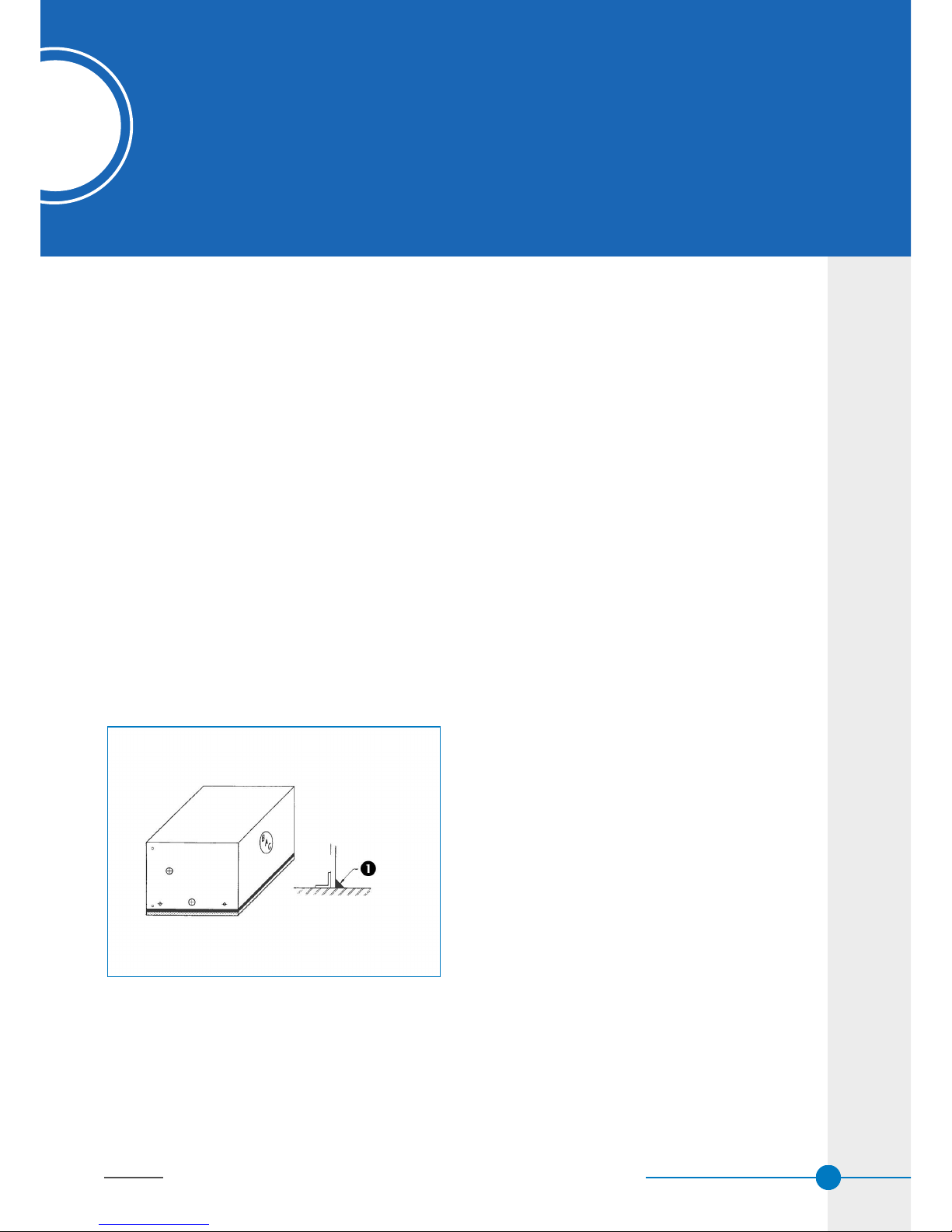
Threaded coil connection with pressure release valve on Ice Thermal Storage unit for Glycol execution.
1. Closed pressure release valve of upper coil connection.
2. After releasing the low pressure inert gas, cut coil connection here.
Caution
ONCE THE COIL IS NO LONGER PROTECTED BY THE INERT GAS, PROPER ACTIONS
AGAINST CORROSION MUST BE TAKEN ON SITE.
Freeze Protection
These products must be protected against damage and/or reduced effectiveness due to possible freeze-up by
mechanical and operational methods. Please refer to the BAC Product & Application Handbook or contact your
local BAC Balticare representative for recommended protection alternatives.
Safety Precautions
All electrical, mechanical and rotating machinery constitutes a potential hazard, particularly for those not familiar
with its design, construction and operation. Accordingly, adequate safeguards (including use of protective
enclosures where necessary) should be taken with this equipment both to safeguard the public (including minors)
from injury and to prevent damage to the equipment, its associated system and the premises.
If there is doubt about safe and proper rigging, installation, operation or maintenance procedures, contact the
equipment manufacturer or his representative for advice.
When working on operating equipment, be aware that some parts may have an elevated temperature. Any
operations on elevated level have to be executed with extra care to prevent accidents.
Air piping between air pump and TSU-C/D can have temperatures above 40°C. Insulate the piping if necessary to
prevent personal injury.
AUTHORIZED PERSONNEL
The operation, maintenance and repair of this equipment should be undertaken only by personnel authorized and
qualified to do so. All such personnel should be thoroughly familiar with the equipment, the associated systems
and controls and the procedures set forth in this and other relevant manuals. Proper care, personal protective
equipment, procedures and tools must be used in handling, lifting, installing, operating, maintaining and repairing
this equipment to prevent personal injury and/or property damage. Personnel must use personal protective
equipment where necessary (gloves, ear plugs, etc...)
W W W . B A L T I M O R E A I R C O I L . E U
6

MECHANICAL SAFETY
Mechanical safety of the equipment is in accordance with the requirements of the EU machinery directive.
Depending upon site conditions it also may be necessary to install items such as bottom screens, ladders, safety
cages, stairways, access platforms, handrails and toe boards for the safety and convenience of the authorized
service and maintenance personnel.
At no time this equipment should be operated without all access cover panels and access doors in place.
For more information consult your local BAC Balticare representative.
ELECTRICAL SAFETY
Each fan associated with this equipment should be installed with a lockable disconnect switch located within sight
of the equipment.No service work should be performed on or near the fans unless motors are electrically isolated.
Each motor associated with this equipment should be installed with a lockable disconnect switch located within
sight of the equipment.No service work should be performed on or near the motors unless motors are electrically
isolated.
LIFTING
Caution
FAILURE TO USE DESIGNATED LIFTING POINTS CAN RESULT IN A DROPPED LOAD
CAUSING SEVERE INJURY, DEATH AND/OR PROPERTY DAMAGE. LIFTS MUST BE
PERFORMED BY QUALIFIED RIGGERS FOLLOWING BAC PUBLISHED RIGGING
INSTRUCTIONS AND GENERALLY ACCEPTED LIFTING PRACTICES. THE USE OF
SUPPLEMENTAL SAFETY SLINGS MAY ALSO BE REQUIRED IF THE LIFT CIRCUMSTANCES
WARRANT ITS USE, AS DETERMINED BY THE RIGGING CONTRACTOR.
LOCAL REGULATIONS
Installation and operation of cooling equipment may be subject to local regulations, such as establishment of risk
analysis. Ensure regulatory requirements are consistently met.
Non-walking Surfaces
Access to and maintenance of any component needs to be performed in accordance with all local applicable laws
and regulations. If the proper and required access means are not present, temporary structures need to be
foreseen. Under no circumstance can one use parts of the unit, that are not designed as an access mean, unless
measures can be taken to mitigate any risks that might occur from doing so.
Modifications by others
Whenever modifications or changes are made by others to the BAC equipment without written permission of BAC,
the party who has done the modification becomes responsible for all consequences of this change and BAC
declines all liability for the product.
W W W . B A L T I M O R E A I R C O I L . E U
7
1 General Information

Warranty
BAC will guarantee all products to be free from manufactured defects in materials and workmanship for a period of
12 months from the date of shipment. In the event of any such defect, BAC will repair or provide a replacement.
For more details, please refer to the Limitation of Warranties applicable to and in effect at the time of the
sale/purchase of these products. You can find these terms and conditions on the reverse side of your order
acknowledgement form and your invoice.
W W W . B A L T I M O R E A I R C O I L . E U
8

2 Rigging
2 Rigging W W W . B A L T I M O R E A I R C O I L . E U
9
RIGGING
General Notes
1. To simplify rigging and installation, units are shipped in one piece, so only one lift is required. It is important to
follow the guidelines listed below when rigging these units.
2. Lifting devices have been provided for short lifts and final positioning. The table "Approximate Shipping weights
& Dimensions" shows the location of the lifting devices for each tank size.
3. Lifting and transportation of the equipment by means of lift trucks is not permitted, as this may result in serious
damage of the tank bottom and the ice coils.
4. Spreader bars of the full width of the section must be used between the lifting cables to prevent damage to the
section.
5. For extended lifts or where hazards exist, it is recommended to use the lifting devices in conjunction with
safety slings placed under the unit.
Support Requirements
ON A LEVEL CONCRETE PAD
The unit should be continuously supported on a level concrete pad. After the unit is set into final position, the tank
bottom should be sealed airtight all around to prevent condensation formation (see figure). The sealer is shipped
loose with the unit, together with the air pump.
Unit continuously supported on a level concrete pad
1. Seal around base of tank
TSU-C-D
2

ON 3 I-BEAMS
If continuous support is not possible, an alternative recommended support arrangement consists of 3 parallel I-
beams extending the full length of the unit: 2 supporting beams should be located along the unit length and 1 beam
should be located on the centreline of the unit. (see figure)
Each beam should be sized for 65% of the total operating weight. If a unit is installed on I-beams additional
insulation of the tank bottom is necessary to avoid the formation of condensation.
Installation on 3 I-beams
ON A ROOF
For installation of the unit on a roof, additional field insulation between tank bottom and the roof is required to
prevent condensation formation on the ceiling of the floor below (see figure). Recommended insulation material is a
vapour tight cork layer.
Installation on the roof
1. Cork layer
Rigging Method
RECOMMENDED LIFTING METHOD
The recommended method of rigging the unit is shown in the figure.
W W W . B A L T I M O R E A I R C O I L . E U
10

Recommended lifting method
1. Safety slings
TSU 95C - TSU 1050C: H= 2160 mm
TSU 790D – TSU 1440D: H= 2415 mm
Caution
THE LIFTING CABLES MUST BE VERTICAL IN BOTH PLANES AS SHOWN.
Caution
WHEN LIFTING UNITS AS SHOWN, SOME TANK COVERS MUST BE REMOVED TO PROVIDE
ACCESS TO THE LIFTING EARS. ENSURE THAT THE LIFTING CABLES DO NOT DAMAGE THE
REMAINING COVERS.
Three lifting beams are required. The lifting ears and tank are not designed to support the loads resulting from lifts
employing less than 3 lifting beams as shown in hereunder.
Lifting methods not permitted
W W W . B A L T I M O R E A I R C O I L . E U
11
2 Rigging
2 Rigging

Model
TSU C/D
L x W
Dimensions
Approx
Shipping
weight (kg)
A
(mm)
B
(mm)
C
(mm)
TSU 95C
TSU 115C
3073 x 1308
3683 x 1308
2620
2860
1597
2403
738
640
1124
1124
TSU 120C
TSU 145C
TSU 170C
TSU 200C
TSU 225C
3073 x 1605
3683 x 1605
4293 x 1605
4877 x 1605
5486 x 1605
2935
3355
3955
4330
4745
1597
2403
2899
3371
3276
738
640
702
753
1105
1416
1416
1416
1416
1416
TSU 185C
TSU 230C
TSU 270C
TSU 310C
TSU 350C
3073 x 2400
3683 x 2400
4293 x 2400
4877 x 2400
5486 x 2400
4130
4730
5285
6065
6620
1597
2403
2889
3371
3276
738
640
702
753
1105
2216
2216
2216
2216
2216
TSU 290C
TSU 340C
TSU 400C
TSU 450C
3683 x 2982
4293 x 2982
4877 x 2982
5486 x 2982
5600
6245
7210
7900
2403
2889
3371
3276
640
702
753
1105
2797
2797
2797
2797
TSU 480C
TSU 590C
TSU 700C
TSU 800C
TSU 910C
TSU 1050C
6096 x 2982
7290 x 2982
8509 x 2982
9703 x 2982
10922 x 2982
12725 x 2982
9090
10515
11850
13820
15205
17455
3430
4618
5889
5941
6300
6899
1333
1336
1310
1881
2311
2913
2797
2797
2797
2797
2797
2797
TSU 790D
TSU 940D
TSU 1080D
TSU 1220D
TSU 1440D
7290 x 3582
8509 x 3582
9703 x 3582
10922 x 3582
12725 x 3582
13975
15680
18150
19800
22370
4618
5889
5941
6300
6899
1336
1310
1881
2311
2913
3397
3397
3397
3397
3397
Approximate Shipping Weights and Dimensions
ROLLING INTO POSITION
As an alternative to lifting, the unit can be rolled into position. If rollers are used they should be placed under the
unit and must exceed the unit width. The span between the rollers should not exceed 1 m.
Piping
WATER CONNECTIONS
Balancing valves must be installed on all water inlet connections to adjust the flow through each connection.
REFRIGERANT CONNECTIONS ON SITE
All connections in the external pipework (installed by others) must be leak free and tested accordingly. All piping
external to BAC cooling equipment must be supported separately.
W W W . B A L T I M O R E A I R C O I L . E U
12

PURGE REQUIREMENTS
The installer of BAC equipment must ensure proper system purging of air prior to operation. Entrained air can
obstruct the proper flow of glycol solution, resulting in higher operating pressures than design and reduced thermal
storage capacity.
Air Pump Installation
The standard BAC delivery consists of a centrifugal air pump (with an inlet air filter), a threaded adaptor and a
flexible discharge sleeve to be connected to the customer provided air piping. A non-return valve is shipped loose
with the air pump for field installation.
After the unit has been rigged into position, the air pump can be installed. The recommended air piping is shown in
the figure: the air supply is taken from the ambient air. The air pump is to be mounted on a clean, dry and vibration
free surface which is flat and will support the unit. Special pads are not required.
The mounting surface should be levelled and the pumps must be securely bolted in place. It is recommended that,
in case of outdoor installation, the air pump is installed under a shelter. The air pump should be located within 6
meters of the air distribution inlet piping. If a more remote location of the air pump is required, consult your local
BAC representative.
Recommended air pump piping arrangement
1. Non-return valve
2. Steel pipe for initial 3m; then PVC for remainder of air supply (by others)
3. Filter
4. Air pump
W W W . B A L T I M O R E A I R C O I L . E U
13
2 Rigging
2 Rigging

W W W . B A L T I M O R E A I R C O I L . E U
INSPECTION PRIOR TO START-UP
General
Prior to start-up, the following services, which are described in detail in the Operating and Maintenance Manual
(see Table "Recommended Maintenance and Monitoring Programme" on page 2) must be performed.
Proper start-up procedures and scheduled periodic maintenance will prolong the life of the equipment and ensure
trouble-free performance for which the unit is designed.
14
TSU-C-D
3
3 Inspection Prior to Start-up

4 Further Assistance & Information
4 Further Assistance & Information W W W . B A L T I M O R E A I R C O I L . E U
15
FURTHER ASSISTANCE & INFORMATION
Balticare
BAC has established a specialized independent total care company called Balticare. The BAC Balticare offering
involves all elements required to ensure a safe and efficient operation of your evaporative cooling products. From a
full range of risk assessment to selective water treatment, training, testing, record keeping and annual system
overview.
For more details, contact BAC Balticare at www.balticare.com or you can also contact your local BAC
representative for further information and specific assistance at www.BaltimoreAircoil.eu.
More Information
REFERENCE LITERATURE
• Eurovent 9-5 (6) Recommended Code of Practice to keep your Cooling System efficient and safe.
Eurovent/Cecomaf, 2002, 30p.
• Guide des Bonnes Pratiques, Legionella et Tours Aéroréfrigérantes. Ministères de l'Emploi et de la Solidarité,
Ministère de l'Economie des Finances et de l'Industrie, Ministère de l'Environnement, Juin 2001, 54p.
• Voorkom Legionellose. Minsterie van de Vlaamse Gemeenschap. December 2002, 77p.
• Legionnaires' Disease. The Control of Legionella Bacteria in Water Systems. Health & Safety Commission.
2000, 62p.
• Hygienische Anforderungen an raumlufttechnische Anlagen. VDI 6022.
INTERESTING WEB SITES
• www.BaltimoreAircoil.eu
• www.Balticare.com
• www.eurovent-certification.com
• www.ewgli.org
• www.ashrae.org
• www.uniclima.org
• www.aicvf.org
• www.hse.gov.uk
TSU-C-D
4

W W W . B A L T I M O R E A I R C O I L . E U
16

W W W . B A L T I M O R E A I R C O I L . E U

W W W . B A L T I M O R E A I R C O I L . E U

W W W . B A L T I M O R E A I R C O I L . E U

COOLING TOWERS
CLOSED CIRCUIT COOLING TOWERS
ICE THERMAL STORAGE
EVAPORATIVE CONDENSERS
HYBRID PRODUCTS
PARTS & SERVICES
www.BaltimoreAircoil.eu
info@BaltimoreAircoil.eu
www.balticare.com
info@balticare.com
Please refer to our website for local contact details.
Industriepark - Zone A, B-2220 Heist-op-den-Berg, Belgium
©Baltimore Aircoil International nv
This manual suits for next models
26
Table of contents
Popular Industrial Electrical manuals by other brands

Murata
Murata GRM0225C1ER90WA03 Series Reference sheet

Murata
Murata GCJ319R71H104KA01 Series Reference sheet

Murata
Murata GRM0335C1H160GA01 Series Reference sheet

Murata
Murata GRM1557U1A152JA01 Series Reference sheet

Guardian
Guardian 10800 instruction manual

Murata
Murata GRM0335C1H1R2BA01 Series Reference sheet

Murata
Murata GRM0335C1H3R1CA01 Series Reference sheet

Siemens
Siemens SIMATIC RTLS operating instructions

Eaton
Eaton Moeller EU5E-SWD-8DX Instruction leaflet

Panasonic
Panasonic LP-310 Operation manual

Murata
Murata LLA319R71A105MA01 Series Reference sheet

Murata
Murata GQM1555C2D5R0BB01 Series Reference sheet