20 Assemble the leadscrew gear. with
driving pins or Woodruff key. onto the
leadscrew end. position to give .015"
clearance from the gearbox face and
secure with the grubscrew. See Fig. 22.
Final Assembly
21 Drive the 1/4" B.S.F. Stud No. 220
into the lower of the three tapped
holes at the end of the lathe bed. and
screw an one each of the lock nuts and
washers No- 222 and 221 (nut first).
Attach the new change wheel guard
assembly to the machined end face of
the gearbox and cover No. 260 using
in the upper hole. the 2 B.A. cap
screw and washer Nos. 219 and 255; in
the lower hole. the hexagon head
screw and washer Nos. 217 and 221.
Screw the remaining nut and washer
Nos. 222 and 221 (washer first) on to
the stud. No. 220. and adjust the
locknuts to secure the guard backplate
without distortion
.
(Note: this gear is keyed with the No.
404 Woodruff key which is supplied).
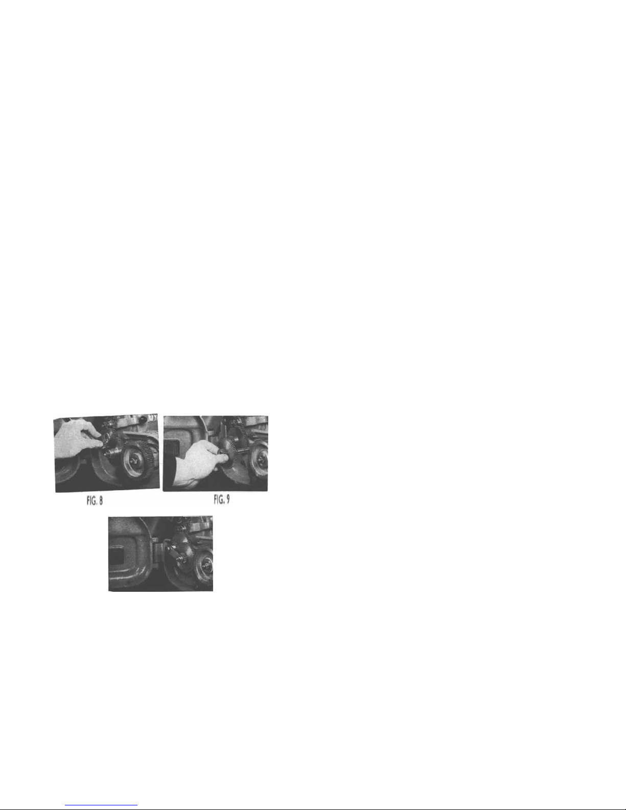
16M Fit the leadscrew back into the
machine. feeding it through the clasp
nut and replacing the collar (to the left
of the bracket) before passing through
the right-hand bracket.
17M Mount the gearbox back into
position ensuring that the rubber
sealing washer is correctly positioned
in the recess before tightening the
captive screw. At this stage all 3 screws
should only be lightly tightened. Replace
the shortened leadscrew guard on the
apron.
IBM Replace the driving pin, distance
collar (or leadscrew handwheel, if
fitted). and Simmonds nut. Tighten the
Simmonds nut to position the collar to
the left of the bracket and tighten the
socket set screw to secure the collar.
Release the Simmonds nut and adjust
to allow the leadscrew to rotate without
end play
Ali
earbox
19 The gearbox bearing should now be
Centralised with the leadscrew, and at
the same time levelled (i.e. set parallel
with the top surface of the Lathe ways).
Adjustment of the position of the box.
before final tightening, is accomplished
by inserting wooden wedges under each
end of the box, alternatively jack
screws can be used. Levelling can
either be carried out with a dial gauge
as shown in diagram Fig. 23 or with an
accurate spirit level (check in relation to
top surface of bed ways). Misalignment
in the vertical plane will be shown by
vertical deflection of the leadscrew.
when the clasp nut is operated.
Finally tighten the three gearbox
securing screws, check the leadscrew
for free rotation and replace top cover
No. 260. (SET THE UPPER LEVER No.
197 TO A NEUTRAL POSITION WHILST
CHECK IS CARRIED OUT).
22 Place one of the two 3/8" dia.
washers on the anchor pin No. 203.
Assemble the gear quadrant No. 202
on to the input shaft housing No. 179.
and over the anchor pin. Lightly secure
the gear quadrant to the anchor pin
with the remaining 3/8" dia. washer and
3/8" B.5-F. nut- Fig. 24 Release the
grubscrew No. 195 which secures the
anchor pin in the gearbox and position
the gear quadrant to align the quadrant
gears with the 24T. CHANGE WHEEL on
the tumbler reverse stud. Secure the
anchor pin in this position. and tighten
the 3/8" B.S.F. nut.
23 Tighten the gear quadrant pinch
screw No. 139 (the pinch screw must
not be excessively tightened, as this
can cause stiffness on the input shaft
No. 183).
24 Set the various controls as
described on page 9 and check for
freedom of leadscrew and gearing as at
A and 3 at foot of same page.
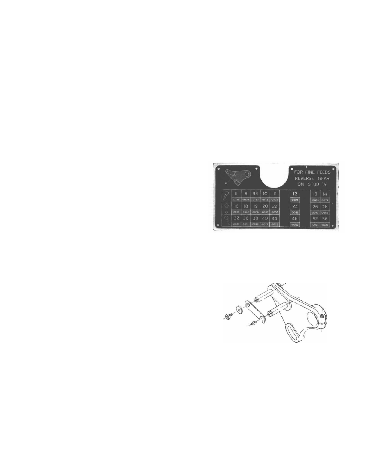
25 Replace the reversible cluster gear in
the position which gives the fine pitch
range (i.e. with the 19T- gear
outermost). and test for free rotation
right through by manual rotation of the
headstock spindle- Fig. 26.
26 Before operating the Lathe.
remove the level plug fat the right-hand
end of the box) and fill to over-flowing
with S.A.E. No. 30 oil. The tumbler
reverse gear pins and quadrant gear
pins should be lubricated frequently_
Occasional application of the oil gun to
the oil nipples on the gear box will be
sufficient.
FIG. 24