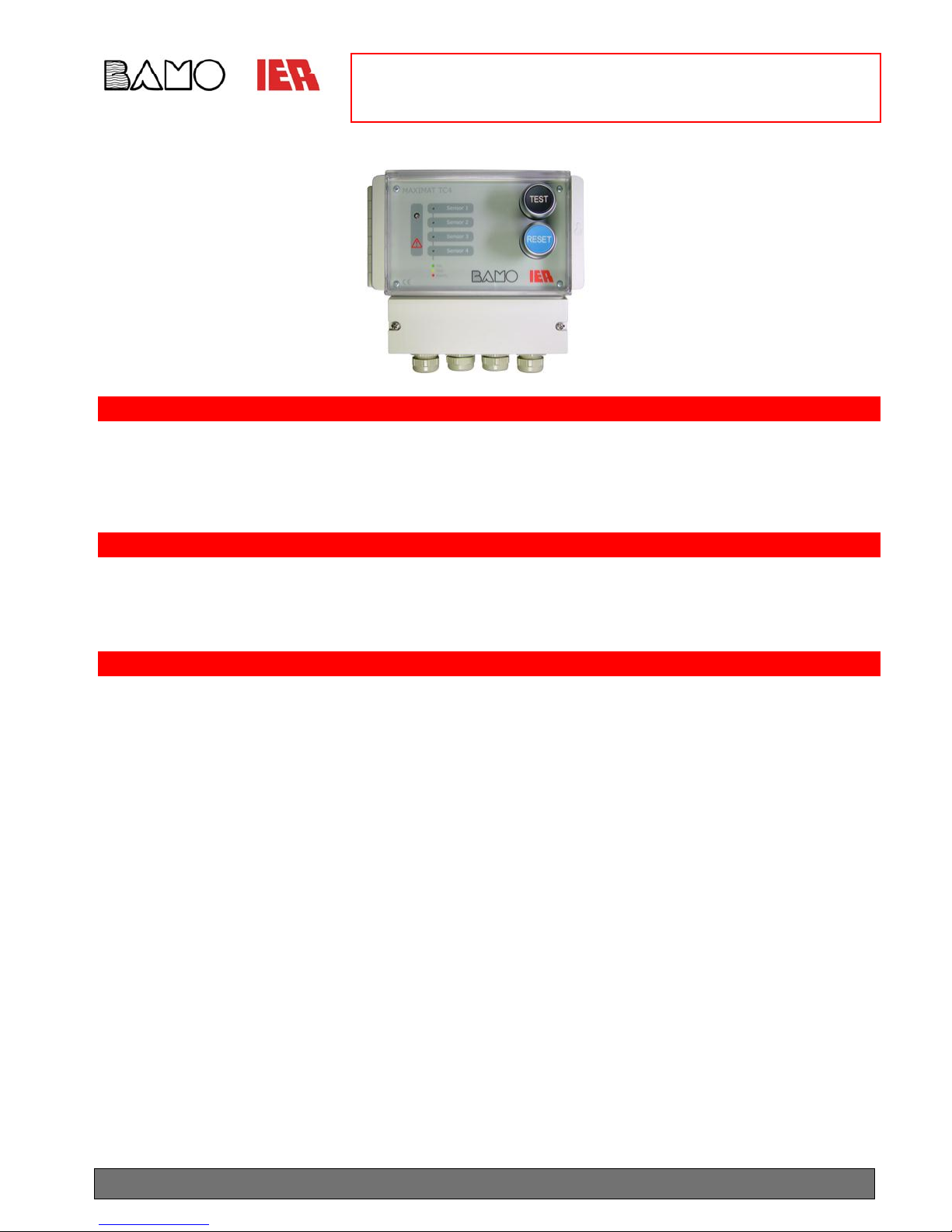
OPERATING INSTRUCTIONS
MAXIMAT TC4 SIGNALLING DEVICE
BAMO IER GmbH Pirnaer Str. 24 D-68309 Mannheim, Germany
SU3312a.doc 03/15 2
Technical Data (continued):
Indication: 4 LEDs (multi-coloured)
Blinking red alarm pending
Continuous red alarm acknowledged
Blinking yellow defective sensor
Continuous yellow test in progress
Continuous green sensor active
Dark LED no sensor connected
1 piezo signal generator: > 70dB (A) at 1m
1 extra-bright flashing LED for group alarm
Controls: Reset button for acknowledging alarms
Test button for system test
CE Mark:
In accordance with low-voltage directive 2006/95/EC and EMC directive 2004/108/EC
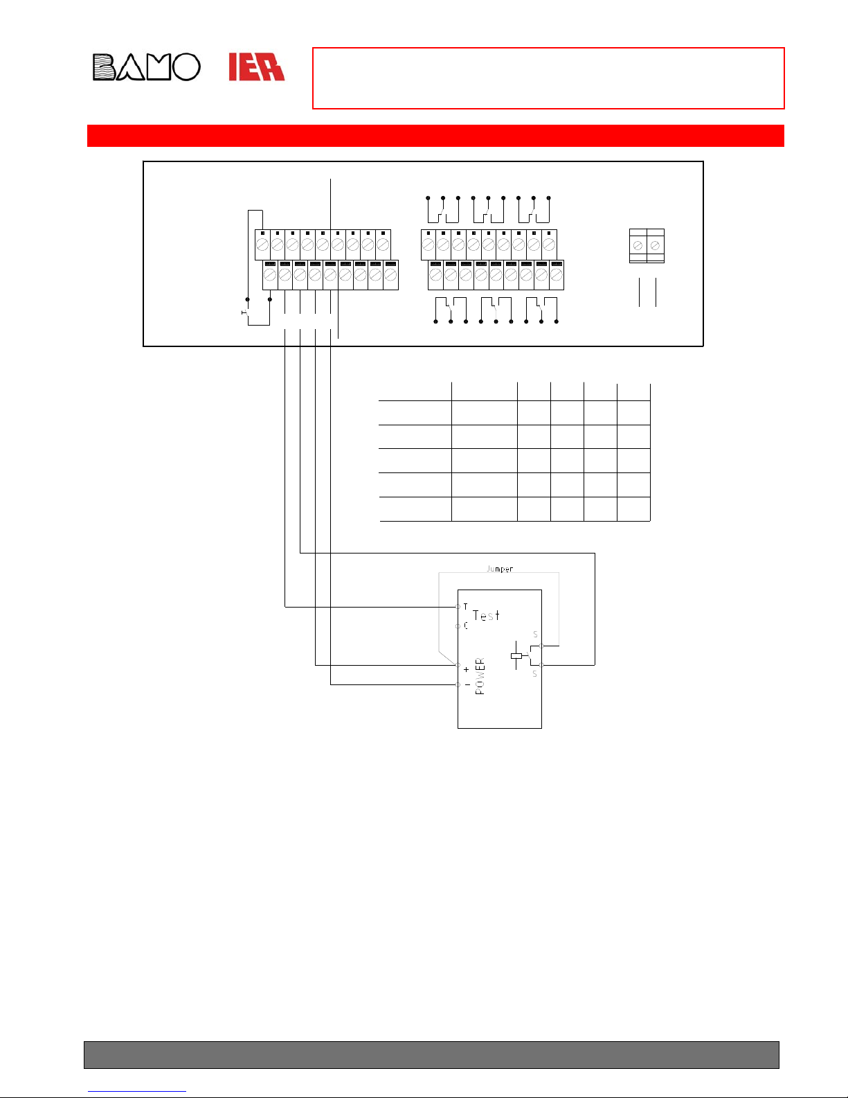
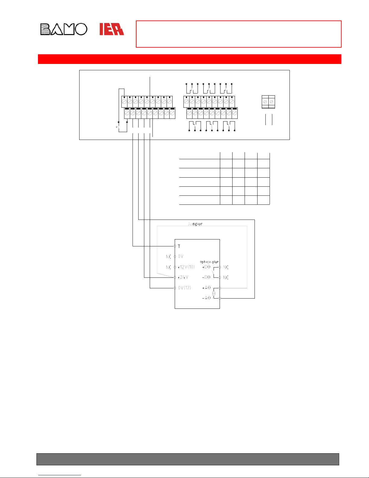
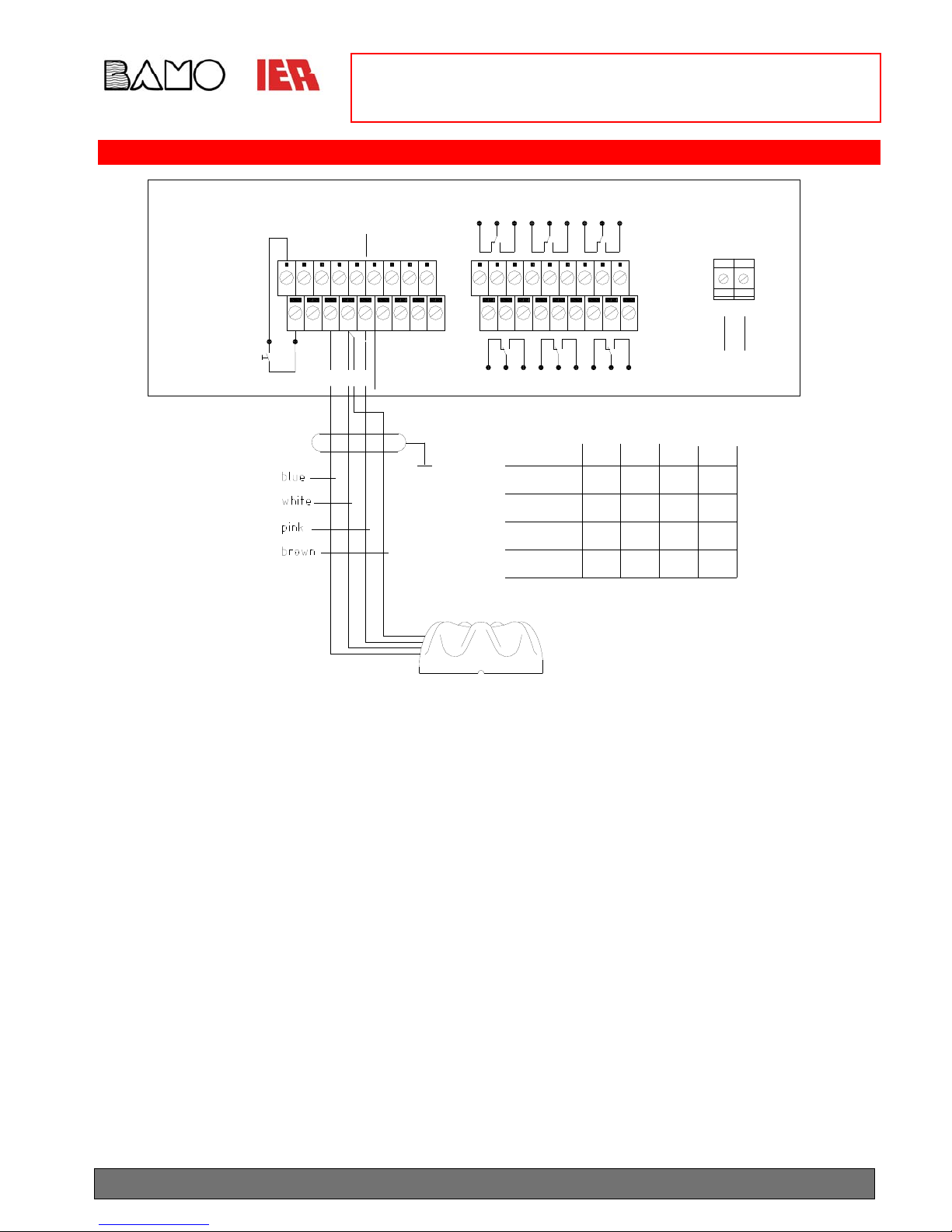
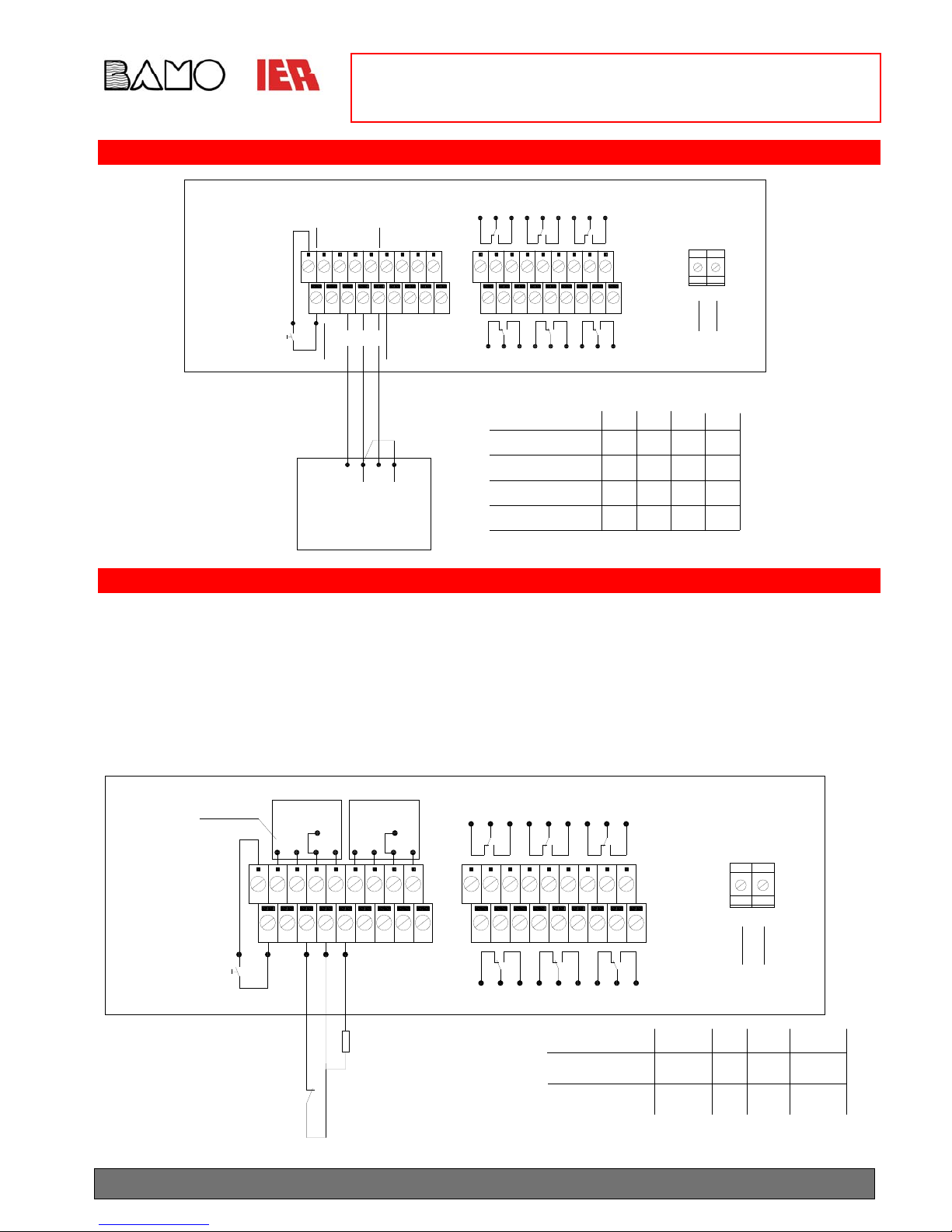
Terminal Assignments:
Terminal Number Function
L (+) Mains, 230V AC / +24V DC supply power
N (-) Mains, 230V AC / 0V DC supply power
1 / 19 External test button (floating NO contact)
Channel 1 Channel 2 Channel 3 Channel 4 Alarm Channels
2 20 6 24 Test signal for sensors with T-connector
3 21 7 25 Alarm input:
4 22 8 26 Sensor supply voltage
5 23 9 27 0 V reference potential
13 31 10 28 Output relay, NC contact: alarm
14 32 11 29 Output relay, root: alarm
15 33 12 30 Output relay, NO contact: alarm
16 Output relay, NC contact: external buzzer
17 Output relay, root: external buzzer
18 Output relay, NO contact: external buzzer
34 Output relay, NC contact: group alarm
35 Output relay, root: group alarm
36 Output relay, NO contact: group alarm
Note: The alarm output relays (channels 1 to 4) and the group alarm relay are pulled in (closed-circuit current) as long as no alarm is
pending. These relays are released in the event of an overfill /leakage alarm or mains power failure.
In all of the following wiring diagrams, the relays are shown in the de-energised state in accordance with the standards (mains power =
OFF)!
The relay for the external buzzer is pulled in when an alarm occurs, and is released after resetting.