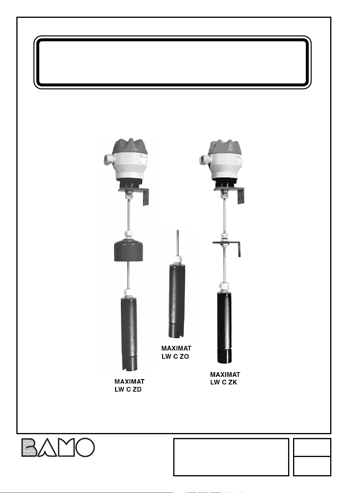
Bamo MAXIMAT LW C Series User manual

Leakage detection sensor
MAXIMAT®LW C
MESURES
22, Rue de la Voie des Bans - 95 100 ARGENTEUIL - FRANCE
Fax : (+33) 01 34 10 16 05 - Site : http://www.bamo.fr
07-03-2007
MES
555-03/1
555 M1 03 D
II
IINN
NNSS
SSTT
TTRR
RRUU
UUCC
CCTT
TTII
IIOO
OONN
NN
MM
MMAA
AANN
NNUU
UUAA
AALL
LL
MAXIMA
MAXIMAT
T®
®L
LW C
W C
Leakage detection sensor

555 M1 03 D 07-03-2007 Page 2
CAUTION
Installation, initial start-up and maintenance may only be performed by trained personnel. All applicable European and national
regulations regarding installation of electrical equipment must be adhered to.
- The device may only be connected to supply power which complies with the specifications included in the technical data and on
the serial plate.
- The device must be disconnected from all sources of power during installation and maintenance work!
- The device may only be operated under the conditions specified in the operating instructions!
DESCRIPTION
The MAXIMAT LW CZ ... compact leakage sensor is used as a leakage monitoring device for permanently installed containers used for
the storage of non-flammable, water endangering liquids.It is equipped with three different output circuits:
- A binary output for controlling a coupling relay or the digital input at a PLC
- A 0 to 20 mA current output for controlling an analog input channel, e.g. a programmed logic controller (PLC)
- Self-monitoring measuring circuit in combination with the MAXIMAT SHR C... measuring transducer with 2-wire connection
Applications: Note that stored liquids may not tend to precipitate insulating or conductive sediments.C.s.
CE mark: In accordance with low-voltage directive (73/23/EWG), EMC directive (89/336/EWG) and EN 50 082-2:1995, EN 55
011 (class A):1998C.
TECHNICAL FEATURES
Supply power: 24 V DC ± 10%
CAUTION: power supply with current limiting or 250 mA fuse recommended
Connected load: Approx. 3 W
Ambient temperature: -20 to +60° C
Container pressure: Atmospheric (0.8 to 1.1 bar)
Hysteresis: About 2 mm
Switching height: 5 mm as the minimum
Connecting cable:
6 m long PCV cable
shielded, 7x0,5 mm2for MAXIMAT LWC.
shielded, 7x0,34 mm2for MAXIMAT LWC25
Outputs: – Binary output: +DO / -DO max. 30 mA at 24 V DC
– Current output: +AO / -AO, 0 to 20 mA
– Output for MAXIMAT SHR C... measuring transducer
Terminals: Housing: IP 65 – PBT – EN 60529
Screw terminals, IP 20 for MAXIMAT LW CZD and K
Maximum wire cross-section: 2.5 mm2
DIP Switch: Operating Mode DIP1 DIP2 DIP3 DIP4
Binary output ON ON ON OFF
Current output OFF OFF OFF OFF
MAXIMAT SHR C OFF * OFF * OFF * OFF *
* = Default setting
CAUTION: be sure to examine the DIP switch settings before switching supply power on!
Indicators: Green LED on the connector PCB:
Run = LED illuminated
Alarm / error = LED off
Measuring circuit for use with SHR C...
Cable inductance: Maximum approx. 5 mH
Cable capacitance: Maximum approx. 0.5 μF
Measuring circuit cable
Length: Maximum 300 m
Wire cross-section: Minimum 0.5 mm2
DIBT Approval Approval no. Z-65.40-316 for overfill inhibitors and leakage sensors in accordance with WHG §19
Note: The accompanying “General Building Supervisory Approval no. Z-65.40-316” is an integral part of the operating instructions
and all stipulations contained therein must be adhered to !

MAXIMAT LW C...
Detection sensor Glass carbon
Probe tube PE-HD (polyethylene)
Cap dia.63 mm (...CZD) PVC (polyvinyl chloride)
Bracket PVC (polyvinyl chloride)
Pg fitting PA (polyamide)
Seal / Pg fitting NBR (perbunan)
Measuring cable PVC (polyvinyl chloride)
MAXIMAT LW C25...
Detection sensor Glass carbon
Probe tube PE (polyethylene)
Cap dia. 32 mm(...CZD) PVC (polyvinyl chloride)
Bracket PVC (polyvinyl chloride)
Pg fitting PA (polyamide)
Seal / Pg fitting NBR (perbunan)
Measuring cable PVC (polyvinyl chloride)
INSTALLATION
The leakage sensor’s probe is suspended such that it hangs into the catch basin of the storage tank to be monitored.
The probe may make contact with the outside wall of the catch basin, or may stand on its floor.
The cable must be secured such that the probe is always positioned vertically.
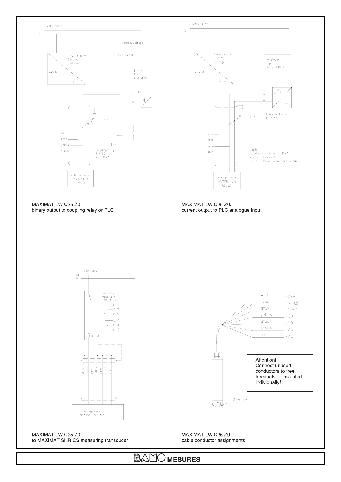
The connector cable between the probe and the measuring transducer is pulled through the Pg fitting mounted to the bracket or the
cap until the portion of the cable inside the catch basin holds the probe in the vertical position.
When installed in a free-hanging manner, it must be assured that the connector cable is only pulled far enough through the
adjustor fitting to allow for a maximum clearance of 45 mm between the probe and the catch basin floor, so that the leakage
alarm is triggered at a maximum fill-level of 50 mm.
If the MAXIMAT LW CZ0 variant is used, other suitable mounting components must be used in an appropriate way.
MOUNTING EXAMPLES
Leakage sensor position
For applications involving storage tank catch
basins, the probe must be installed such that the
alarm signal is triggered at a fill-level of 50 mm
or less.
Catch basins, storage tank
The leakage probes are installed inside catch
basins. If the bottom of the probe is in contact with
the floor of the catch basin, the alarm signal is
triggered when the liquid reaches a fill-level of
approximately 5 mm.
555 M1 03 D 07-03-2007 Page 3
PERIODIC TESTING
The leakage probe must be tested for correct functioning at reasonable intervals, although not less than once a year. It is the
sole responsibility of the user to select the utilised test type, as well as a testing interval within the prescribed timeframe.
Testing must be performed which substantiates flawless functioning of the leakage sensor, and correct interaction with all
other associated components. This is assured by means of suitable simulation of a leak, or the physically measured effect
which causes triggering of the alarm signal. If correct functioning of the leakage sensor can be established by other means
(exclusion of function impairing errors), testing can be executed by simulating the appropriate output signal. Further details
concerning test methods are included, for example, in directive VDI / VDE 2180, page 4.
COMPONENT MATERIAL
In the event of a tank leak, the leakage sensor (probe and probe tube) comes into contact with the stored liquid, or vapours and
condensate resulting there for. For this reason, leakage sensor materials must be selected which are adequately resistant to the
liquid to be monitored.
Tank
Fastening angle
Cap with adjustable
thread joint
Catch basin
Sensor

555 M1 03 D 07-03-2007 Page 4
WIRING

555 M1 03 D 28-02-2007 Page 5

555 M1 03 D 07-03-2007 Page 6
NPN output
mA output
This manual suits for next models
3
Table of contents
Other Bamo Accessories manuals