NET R718PE02D User manual

Lidar Material Level Detection Sensor
R718PE02D
Lidar Material Level
Detection Sensor
R718PE02D
User Manual
Copyright© Netvox Technology Co., Ltd.
This document contains proprietary technical information which is the property of NETVOX Technology. It shall be maintained in strict
confidence and shall not be disclosed to other parties, in whole or in part, without written permission of NETVOX Technology. The
specifications are subject to change without prior notice.

1
Table of Contents
1. Introduction ...............................................................................................2
2. Appearance ................................................................................................2
3. Features......................................................................................................3
4. Set up Instruction.......................................................................................3
4.1 On/Off.................................................................................................3
4.2 Network Joining.................................................................................3
4.3 Function Key......................................................................................4
4.4 Sleeping Mode....................................................................................4
5 Data Report.................................................................................................4
5.1 Example of ReportDataCmd..............................................................5
5.2 Example of ConfigureCmd................................................................6
5.3 Example of General Calibration Configuration.................................9
5.4 Set/GetSensorAlarmThresholdCmd ................................................10
6. Application...............................................................................................12
7. Installation ...............................................................................................13
7.1 Precautions for sensor:.....................................................................13
8. Important Maintenance Instruction .........................................................14
2
1. Introduction
R718PE02D is a wireless communication device for Netvox Class C device based on LoRaWAN open protocol. It is a wireless
communication device for the material level detection industry that uses LiDAR radar for single-point ranging. Based on the ToF (Time
of Flight) schematic, the R718PE02D provides stable, accurate, and reliable ranging performance by optimizing the optical system and
built-in algorithms. It is not easily affected by the surface state of the detected object, and the ranging performance can reach up to 25m.
The product is equipped with a unique dust-removal wiper structure. The radar-driven dust-removal wiper can complete the dust removal
operation of the optical mirror, so it can maintain the accuracy of distance measurement in an environment with severe dust pollution and
dust accumulation. The R718PE02D body and the LiDAR sensor communicate through the UART serial communication and transmit
the detected data to other devices for display through the wireless network. It adopts a wireless communication method that conforms to
the LoRaTM protocol standard.
LoRa Wireless Technology:
LoRa is a wireless communication technology dedicated to long distance and low power consumption. Compared with other
communication methods, LoRa spread spectrum modulation method greatly increases to expand the communication distance. Widely
used in long-distance, low-data wireless communications. For example, automatic meter reading, building automation equipment,
wireless security systems, and industrial monitoring. The main features include small size, low power consumption, transmission
distance, anti-interference ability, and so on.
LoRaWAN:
LoRaWAN uses LoRa technology to define end-to-end standard specifications to ensure interoperability between devices and
gateways from different manufacturers.
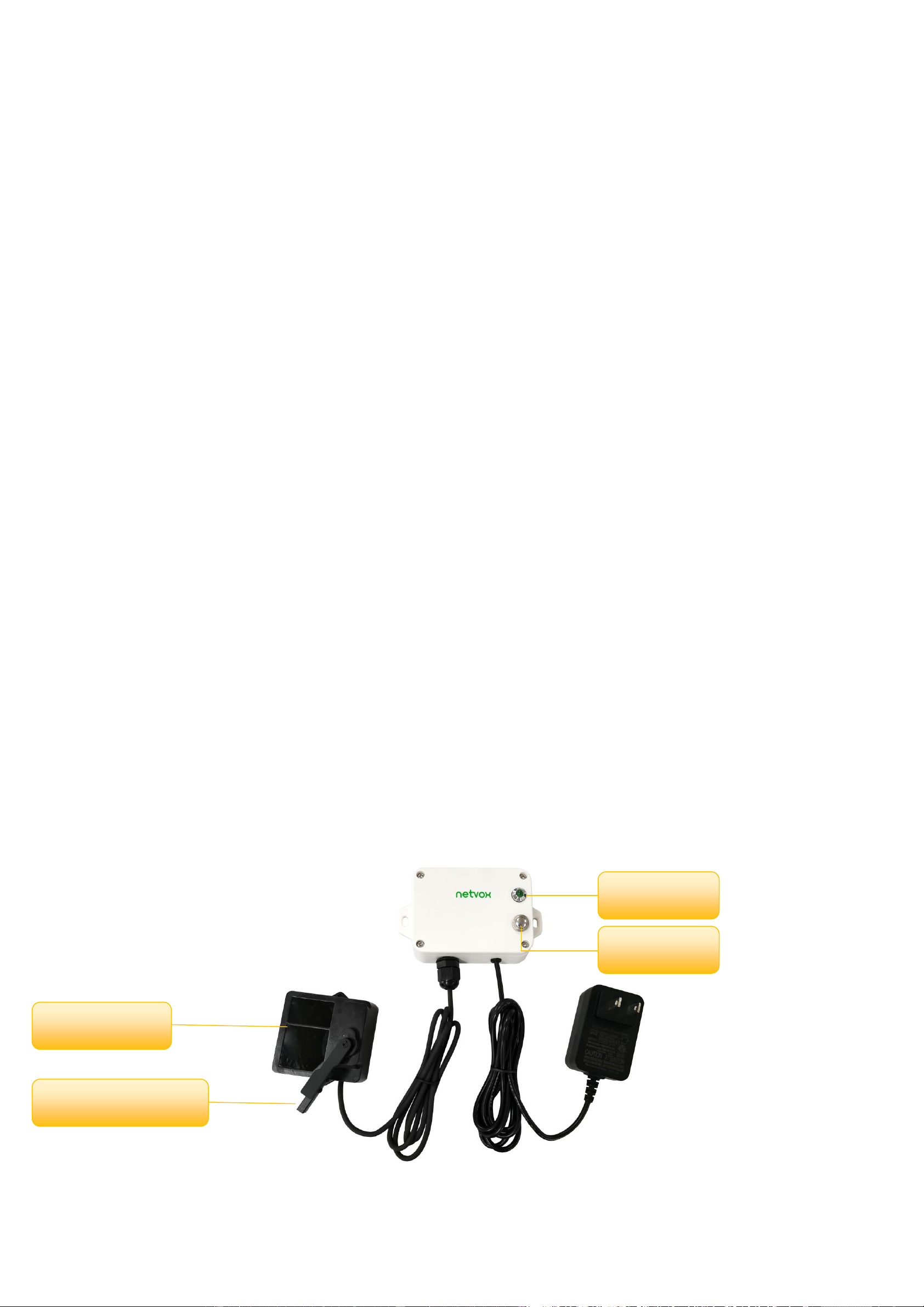
2. Appearance
Indicator
Function Key
LiDAR Sensor
Dust-Removal Wiper

3
3. Features
⚫SX1276 wireless communication module
⚫Powered by 5V DC
⚫IP30 rating
⚫Lidar material level detection with dust removal wiper
⚫Compatible with LoRaWANTM Class C device
⚫Frequency hopping spread spectrum technology
⚫Configuration parameters can be configured through third-party software platforms, data can be read and alarms can be set via SMS
text and email (optional)
⚫Available third-party platforms: Actility/ThingPark, TTN, MyDevices/Cayenne
4. Set up Instruction
4.1 On/Off
Power on
5V DC power supply
Turn on
Connect the power supply
Turn off
Disconnect the power supply
Restart
Press the function key for 5 seconds until the green indicator flashes once.
Release the function key and the indicator will flash 10 times.
Back to factory setting
Press the function key for 10 seconds until the green indicator flashes 20 times
Note
1. When user disconnects the power supply; the device should be off by default.
2. On/off interval is suggested to be about 10 seconds to avoid the interference of capacitor
inductance and other energy storage components.
3. 10 seconds after power on, the device will be in engineering test mode.
4.2 Network Joining
Never joined the network
Turn on the device to search the network to join.
The green indicator remains on for 5 seconds: Success
The green indicator remains off: Fail
Had joined the network
(without factory resetting)
Turn on the device to search the previous network to join.
The green indicator remains on for 5 seconds: Success
The green indicator remains off: Fail
Fail to join the Network
Check the device verification information on the gateway or consult your platform server
provider.

4
4.3 Function Key
Press and hold for 5 seconds
Restart
The green indicator flashes 10 times: Success
The green indicator remains off: Fail
Press and hold for 10 seconds
Factory resetting and restart
The green indicator flashes 20 times: Success
The green indicator remains off: Fail
Press once
The device is in the network: green indicator flashes once and sends a report
The device is not in the network: green indicator remains off
4.4 Sleeping Mode
The device is on and in the
network
Sleeping period: Min Interval
When the report change exceeds setting value or the state changes, the device would send a
data report according to Min Interval.
The device is on but not in the
network
Disconnect the power supply when the device is not in use.
Check the device verification information on the gateway
5 Data Report
After power on, the device will immediately send a version packet report and an attribute packet report.
The device sends data according to the default configuration before any other configuration.
Default:
Max Interval = 0x0384 (900s)
Min Interval = 0x0384 (900s) (detect the material level and voltage at every Min Interval)
reportchange: batteryvoltagechange ---- 0x01 (0.1V)
distancechange ---- 0x012C (300mm)
The interval of the data reports might vary due to the firmware.
R718PE02D default Max Interval = 15min and Min Interval = 15min. (The intervals could be set based on customers’ demands.)
R718PE02D reports the distance between sensor and material, the percentage of the material level, and the ranging range.
Note: 1. The dust removal wiper will automatically wipe once when the device report cycle is reached or when the button is
pressed.
2. The blind zone distance of the sensor is ≤ 0.1m.
Please refer to the Netvox LoRaWAN Application Command and http://www.netvox.com.cn:8888/cmddoc for devices’ data
analysis.
5
Tips
1. Battery Voltage:
If the battery is equal to 0x00, it means that the device is powered by a DC power supply.
2. Version Packet:
When Report Type=0x00 is the version packet, such as 01D5000A00201705030000, the firmware version is 2017.05.03.
3. Data Packet:
When Report Type=0x01 is data packet; If the device data exceeds 11 bytes or there are shared data packets, the Report
Type will have different values.
5.1 Example of ReportDataCmd
FPort: 0x06
Bytes
1
1
1
Var(Fix=8 Bytes)
Version
DeviceType
ReportType
NetvoxPayLoadData
Version–1 Byte –0x01——the Version of NetvoxLoRaWAN Application Command Version
DeviceType–1 Byte –DeviceType of Device
The DeviceType is listed in Netvox LoRaWAN Application DeviceType doc
ReportType –1 Byte –the presentation of the NetvoxPayLoadData, according the DeviceType
NetvoxPayLoadData–Var (Fixed =8bytes)
Device
Devive
Type
Report
Type
NetvoxPayloadData
R718PE02D
0xD5
0x00
SoftwareVersion(1
Byte)
Eg.0x0A-V1.0
HardwareVersion
(1 Byte)
DateCode(4 Byte)
eg 0x20170503
Reserved
(2 Byte)
0x01
Battery
(1Byte,
unit:0.1V)
Status
(1Byte,0x01_On
0x00_Off)
Distance
(2Bytes,
Unit:1mm)
FillLevel
(1Byte,Unit:1%)
SensorStrength
(2Bytes)
CapBattery
(1Byte, unit:0.1V)
Only the battery version
is supported)
0x02
Battery
(1Byte,
unit:0.1V)
ThresholdAlarm(1Byte,
Bit0_Low Distance Alarm,
Bit1_High Distance Alarm,
Bit2_ Low FillLevel Alarm,
Bit3_ High FillLevel Alarm,
Bit4-7:Reserved)
Reserved(6Bytes,fixed 0x00)
6
Example of Uplink1: 01D50100000C1226105700 (FillMaxDistance: 2000mm, DeadZoneDistance: 0mm)
1st byte (01): Version
2nd byte (D5): DeviceType 0xD5 -R718PE02D
3rd byte (01): ReportType
4th byte (00): DC power supply
5th byte (00): Status -OFF
6th-7thbyte (0C12): Distance –3090mm 0C12(Hex) = 3090(Dec), 3090*1mm = 3090mm
8th byte (26): FillLevel –38% 26(Hex) = 38 (Dec), 38*1% = 38%
9th –10th byte (1057): SensorStrength –1057(Hex) = 4183 (Dec)
11th byte (00): Reserved
Example of uplink2: 01D5020001000000000000
1st byte (01): Version
2nd byte (D5): DeviceType 0xD5 -R718PE02D
3rd byte (02): ReportType
4th byte (00): DC power supply
5th byte (01): ThresholdAlarm 3090mm < 4000mm (LowThreshold) //0x01 = 0000 0001 (bin)
6th-11th byte (000000000000): Reserved
5.2 Example of ConfigureCmd
Fport: 0x07
Bytes
1
1
Var (Fix =9 Bytes)
CmdID
DeviceType
NetvoxPayLoadData
CmdID–1 byte
DeviceType–1 byte –Device Type of Device
NetvoxPayLoadData–Var bytes (Max=9bytes)
Description
Device
CmdI
D
Device
Type
NetvoxPayLoadData
ConfigReportReq
R718PE02D
0x01
0xD5
MinTime
(2bytes
Unit:s)
MaxTime
(2bytes
Unit:s)
BatteryChange
(1byte
Unit:0.1v)
DistanceChange
(2byte
Unit:1mm)
Reserved
(2Bytes,
Fixed0x00)
ConfigReportRsp
0x81
Status(0x00_success)
Reserved (8Bytes,Fixed 0x00)
ReadConfigRepor
tReq
0x02
Reserved (9Bytes,Fixed 0x00)
Bit 0 = 1

7
ReadConfigRepor
tRsp
0x82
MinTime
(2bytes
Unit:s)
MaxTime
(2bytes
Unit:s)
BatteryChange
(1byte
Unit:0.1v)
DistanceChange
(2byte
Unit:1mm)
Reserved
(2Bytes,Fixed0x
00)
SetOnDistanceThr
esholdRreq
0x03
OnDistanceThreshold(2byte Unit:1mm)
Reserved (7Bytes,Fixed 0x00)
SetOnDistanceThr
esholdRrsp
0x83
Status(0x00_success)
Reserved (8Bytes,Fixed 0x00)
GetOnDistanceTh
resholdRreq
0x04
Reserved (9Bytes,Fixed 0x00)
GetOnDistanceTh
resholdRrsp
0x84
OnDistanceThreshold(2byte Unit:1mm)
Reserved (7Bytes,Fixed 0x00)
SetFillMaxDistan
ceReq
0x05
FillMaxDistance (2byte Unit:1mm)
Reserved (7Bytes,Fixed 0x00)
SetFillMaxDistan
ceRsp
0x85
Status(0x00_success)
Reserved (8Bytes,Fixed 0x00)
GetFillMaxDistan
ceReq
0x06
Reserved (9Bytes,Fixed 0x00)
GetFillMaxDistan
ceRsp
0x86
FillMaxDistance (2byte Unit:1mm)
Reserved (7Bytes,Fixed 0x00)
SetDeadZoneDist
anceReq(REMAI
N Lastconfig
when resetfac)
0x0B
DeadZoneDistance (2byte Unit:1mm)
Reserved (7Bytes,Fixed 0x00)
SetDeadZoneDist
anceRsp(REMAI
N Lastconfig
when resetfac)
0x8B
Status(0x00_success)
GetDeadZone
DistanceReq
0x0C
Reserved (9Bytes,Fixed 0x00)
GetDeadZone
DistanceRsp
0x8C
DeadZoneDistance (2byte Unit:1mm)
Reserved (7Bytes,Fixed 0x00)

8
(1) Configure R718PE02D report parameters:
MinTime = 1h (3600s, 0x0E10), MaxTime = 1h (3600s, 0x0E10), BatteryChange = 0v (0x00), DistanceChange = 500mm (0x01F4)
Downlink: 01D50E100E100001F40000
Response:
81D5000000000000000000 (configuration success)
81D5010000000000000000 (configuration failure)
(2) Read Configuration:
Downlink: 02D5000000000000000000
Response:
82D50E100E100001F40000 (device current parameter)
(3) Configure R718PE02D report parameter:
FillMaxDistance = 5000mm (0x1388)
Downlink: 05D5138800000000000000
Response:
85D5000000000000000000
(4) Read device parameter:
FillMaxDistance = 5000mm (0x1388)
Downlink: 06D5000000000000000000
Response:
86D5138800000000000000
(5) SetDeadZoneDistance://When restoring factory settings, the last set value will be retained.
Downlink: 0BD5006400000000000000 // Set the device detection dead zone distance to 100mm (0x64).
Response:
8BD5000000000000000000
(6) GetDeadZoneDistance:
Downlink: 0CD5000000000000000000
Response:
8CD5006400000000000000 // Get the device detection dead zone distance of 100mm (0x64).

9
5.3 Example of General Calibration Configuration
FPort: 0x0E
Description
Cmd
ID
SensorType
PayLoad(Fix =9 Bytes)
SetGlobalCalibrateReq
0x01
See below
Channel
(1Byte)
0_Channel1
1_Channel2,etc
Multiplier
(2bytes,
Unsigned)
Divisor
(2bytes,
Unsigned)
DeltValue
(2bytes,
Signed)
Reserved
(2Bytes,
Fixed 0x00)
SetGlobalCalibrateRsp
0x81
Channel (1Byte)
0_Channel1
1_Channel2,etc
Status(1Byte,0x00_success)
Reserved
(7Bytes,
Fixed 0x00)
GetGlobalCalibrateReq
0x02
Channel (1Byte)
0_Channel1
1_Channel2,etc
Reserved
(8Bytes,
Fixed 0x00)
GetGlobalCalibrateRsp
0x82
Channel
(1Byte)
0_Channel1
1_Channel2,etc
Multiplier
(2bytes,
Unsigned)
Divisor
(2bytes,
Unsigned)
DeltValue
(2bytes,
Signed)
Reserved
(2Bytes,
Fixed 0x00)
ClearGlobalCalibrateReq
0x03
Reserved 10Bytes,Fixed 0x00)
ClearGlobalCalibrateRsp
0x83
Status(1Byte,0x00_success)
Reserved (9Bytes,Fixed 0x00)
SensorType = 0x36 Channel = 0x00 // The distance sensor channel fixed value of the device is 00
(When restoring factory settings, the last set value will be retained.)
Multiplier =0x0001 Divisor = 0x0001 DeltValue = 0x0064
Assuming that the original value of the uploaded Distance is 1000mm, and the calibration is increased by 100mm, the uploaded value
is 1100mm.
(1) SetGlobalCalibrateReq:
Downlink: 0136000001000100640000
Response: 8136000000000000000000
(2) GetGlobalCalibrateReq:
Downlink: 0236000000000000000000
Response: 8236000001000100640000
Assuming that the original value of the uploaded Distance is 1000mm, and the calibration is reduced by 100mm, the uploaded value is
900mm

10
(3) SetGlobalCalibrateReq: Calibration reduced by 100mm, Multiplier =0x0001, Divisor = 0x0001, DeltValue = 0xFF9C
Downlink: 01360000010001FF9C0000
Response: 8136000000000000000000
(4) GetGlobalCalibrateReq:
Downlink: 0236000000000000000000
Response: 82360000010001FF9C0000
(5) Clear the calibration value: The uploaded value is back to 1000mm.
ClearGlobalCalibrateReq:
Downlink: 0300000000000000000000
Response: 8300000000000000000000
5.4 Set/GetSensorAlarmThresholdCmd
Fport:0x10
CmdDescriptor
CmdID
(1Byte)
Payload (10Bytes)
SetSensorAlarm
ThresholdReq
0x01
Channel
(1Byte,
0x00_Channel1,
0x01_Chanel2,
0x02_Channel3,etc)
SensorType
(1Byte,
0x00_Disable ALL
SensorthresholdSet
0x2F_ Distance,
0x30_ FillLevel,
SensorHighThreshold
(4Bytes, Unit:same as
reportdata in fport6,
0Xffffffff_DISALBLEr
HighThreshold)
SensorLowThreshold
(4Bytes,Unit:same as
reportdata in fport6,
0Xffffffff_DISALBLErHigh
Threshold)
SetSensorAlarm
ThresholdRsp
0x81
Status
(0x00_success)
Reserved (9Bytes,Fixed 0x00)
GetSensorAlarm
ThresholdReq
0x02
Channel
(1Byte,
0x00_Channel1,
0x01_Chanel2,
0x02_Channel3,etc)
SensorType
(1Byte,
Same as the
SetSensorAlarmThresh
oldReq’s SensorType)
Reserved (8Bytes,Fixed 0x00)
GetSensorAlarm
ThresholdRsp
0x82
Channel
(1Byte,
0x00_Channel1,
0x01_Chanel2,
0x02_Channel3,etc)
SensorType
(1Byte,
Same as the
SetSensorAlarmThresh
oldReq’s SensorType)
SensorHighThreshold
(4Bytes,Unit:same as
reportdata in fport6,
0Xffffffff_DISALBLEr
HighThreshold)
SensorLowThreshold
(4Bytes,Unit:same as
reportdata in fport6,
0Xffffffff_DISALBLErHigh
Threshold)

11
Channel - 1 byte
0x00_Distance
0x01_FillLevel // When restoring factory settings, the last set value will be retained.
(1) SetSensorAlarmThresholdReq: (Set the Distance high threshold to 5m and the low threshold to 4m)
Downlink: 01002F0000138800000FA0 //1388Hex = 5000Dec, 5000*0.001m = 5m; FA0Hex = 4000Dec 4000*0.001m = 4m
Response: 8100000000000000000000
(2) GetSensorAlarmThresholdReq:
Downlink: 02002F0000000000000000
Response: 82002F0000138800000FA0
(3) Clear all sensor thresholds. (Configure the Sensor Type to 0)
Downlink: 0100000000000000000000
Response: 8100000000000000000000

12
6. Application
In the case of detecting the material level of the barn, the device is installed on the top of the barn, and the device is powered on after
fixing. The device collects the distance between the material level and the sensor and the percentage of the material level in the barn at
regular intervals.
H: The height of the barn (this value can be set with the payload command; the “fillmaxdistance” in payload means H)
D: The distance between the device and the material (this value is “distance” in uplinks)
L: The material level (this value can be calculated by the “distance” in uplink and “fillmaxdistance” in payload)
Calculation: L = fillmaxdistacnce –distance
d: The DeadZoneDeistance set by the device (the distance that cannot be detected by the actual device)
FillLevel: The percentage of the material level in the barn. (Status = 0)
The value of the total height of the barn can be set through commands according to the specific scene.
Illustration 1 Illustration 2
FillLevel = ((H - D) / H) * 100% FillLevel = ((H - D) / H-d) * 100%
Note:
The ranging range of the device is:
90% reflectivity, 0Klux 0.1m~25m; 10% reflectivity, 0Klux 0.1m~12m;
90% reflectivity, 100Klux 0.1m~25m; 10% reflectivity, 100Klux 0.1m~12m
The calculate method of material level percentage of
DeadZoneDistance can be set.
13
7. Installation
7.1 Precautions for sensor:
1. When installing the sensor, it is recommended to use M2.5 round head Phillips screws for installation.
Please remove the protective film of the optical lens before use. The lens of front panel of LiDAR cannot be covered. Please keep
it clean. The surface of optical lens is the ranging zero of LiDAR.
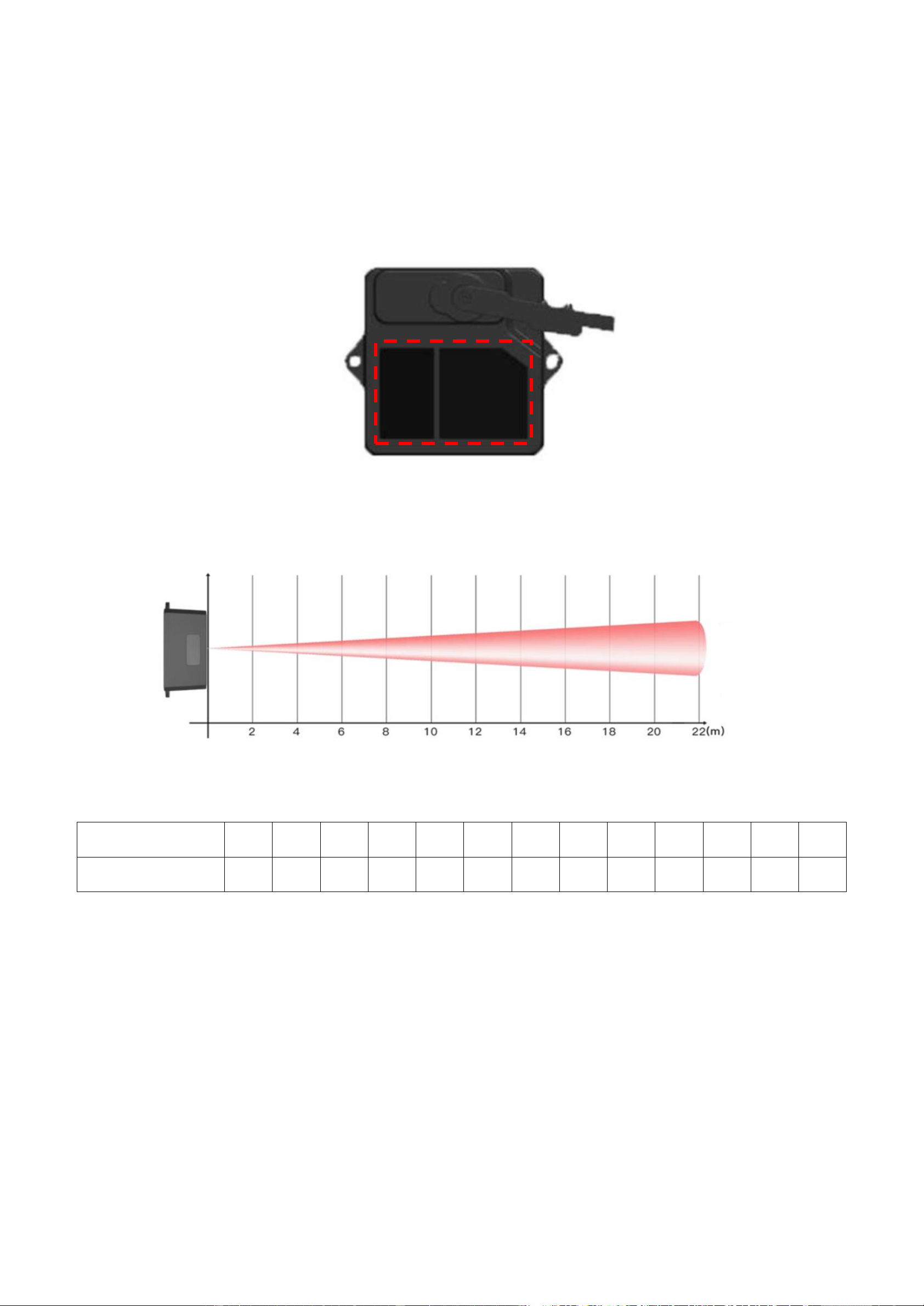
2. The detection angle of the sensor is 3°. At different distances, the size of light spot, namely the edge length of the detection range,
is different.
The spot size at different distances
3. Side length of the detection range at different distances (the detection range is a square)
Distance (m)
1
2
3
4
5
6
7
8
9
10
15
20
22
Spot Size (cm)
5
10
16
21
26
31
37
42
47
52
79
105
115
Spot Size at Different Distances
Note: The side length of the detected target object should be greater than the side length of the detection range of the sensor. When
the side length of the detected object is smaller than the side length of the detection range, the effective range of the radar
will be reduced. When detecting a slope, the sensor can be placed in the middle of the slope.
4. Maintenance and Cleaning
⚫Before/after turning on the device, please check the exposed window mirror and check whether the optical components are dirty,
if dirty, please clean it in time.
⚫The optical components should be cleaned regularly because the device will be placed and operated in a harsh environment.

14
⚫Before cleaning, please turn off the device first, and use a soft cloth to gently wipe the window in the same direction, avoiding
repeated wiping back and forth, which may cause damage to the window mirror.
⚫Do not use alcohol to clean the window mirror as it may be damaged.
⚫Do not disassemble the dust-removal wiper, which may easily cause device failure.
⚫When the steering gear shaft is blocked by dust, the steering gear may be damaged due to increased resistance. It is
recommended to clean the shaft regularly.
8. Important Maintenance Instruction
Kindly pay attention to the following in order to achieve the best maintenance of the product:
•Do not use or store the device in dusty or dirty environments to prevent damage to parts and electronic components.
•Do not store the device in high temperatures. This may shorten the lifespan of electronic components, damage batteries, and deform
plastic parts.
•Do not store the device in cold temperatures. Moisture may damage circuit boards as the temperatures rise.
•Do not throw or cause other unnecessary shocks to the device. This may damage internal circuits and delicate components.
•Do not clean the device with strong chemicals, detergents, or strong detergents.
•Do not apply the device with paint. This may block detachable parts and cause malfunction.
The instructions are applied to your device, battery, and accessories.
If any device is not working properly or has been damaged, please send it to the nearest authorized service provider for service.
Table of contents
Popular Accessories manuals by other brands


Vadsbo
Vadsbo Sensor Narrow installation manual

Awaiba
Awaiba Dragster V3-8K-3.5 Calibration manual

Fisher Scientific
Fisher Scientific Isotemp 500 Series instruction manual

cozee home
cozee home 806335 instruction manual

BITO
BITO PROflow Instructions for assembly and use

IFM Electronic
IFM Electronic PB7 operating instructions