Bamo BAMOPHOX 450 E User manual

MESURES
22, Rue de la Voie des Bans - Z.I. de la Gare - 95100 ARGENTEUIL
Tél : (+33) 01 30 25 83 20 - Web : www.bamo.fr
Dissolved oxygen monitoring
BAMOPHOX 450
11-10-2007 450 M1 02 B
MES
450-02/1
INSTRUCTION MANUAL
INSTRUCTION MANUAL
BB
BBAA
AAMM
MMOO
OOPP
PPHH
HHOO
OOXX
XX
44
4455
5500
00
EE
EE
--
--
MM
MM
Dissolved Oxygen monitor
and controller

Page 2
450 M1 02 B 11-10-2007
Dissolved Oxygen monitor and controller
BAMOPHOX 450 E & M
(Technical information and Manual for LOGGER /RS422 version are on a specific document)
Content
1. TECHNICAL FEATURES Page 3
2. DIMENSIONS 3
3. WIRING 4
4. FRONT PANEL 6
PRESENTATION AND SCROLLING MENU 7
ABOUT BAMOPHOX 8
CONSULTATION / MODIFICATION 8
MEASUREMENT PARAMETERS 9
ATMOSPHERIC PRESSURE 9
SALINITY 9
ADJUST THRESHOLD 1 10
ADJUST THRESHOLD 2 10
ADJUST THRESHOLD 3 11
ON/OFF REGULATION 12
PID REGULATION 13
OUTPUT mA Dissolved Oxygen 14
OUTPUT mA TEMP 14
TEMPERATURE 14
SENSOR CALIBRATION 15
FORCED RELAYS 16
SET UP OF ALARMS 16
SENSOR CLEANING 16
LANGUAGE 16

Page 3
450 M1 02 B 11-10-2007
1. TECHNICAL FEATURES
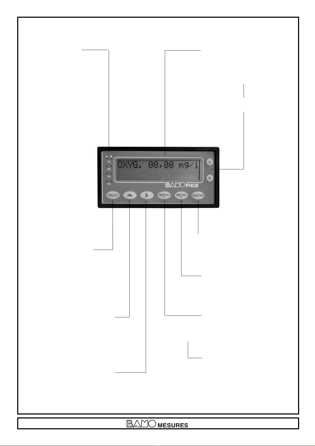
Displayed parameters: Measurement values - Configuration Menu - Temperature value
Display: Back lighted - 2 lines of 16 alphanumerical characters; 9.2 mm high
Indication: LED alarms status
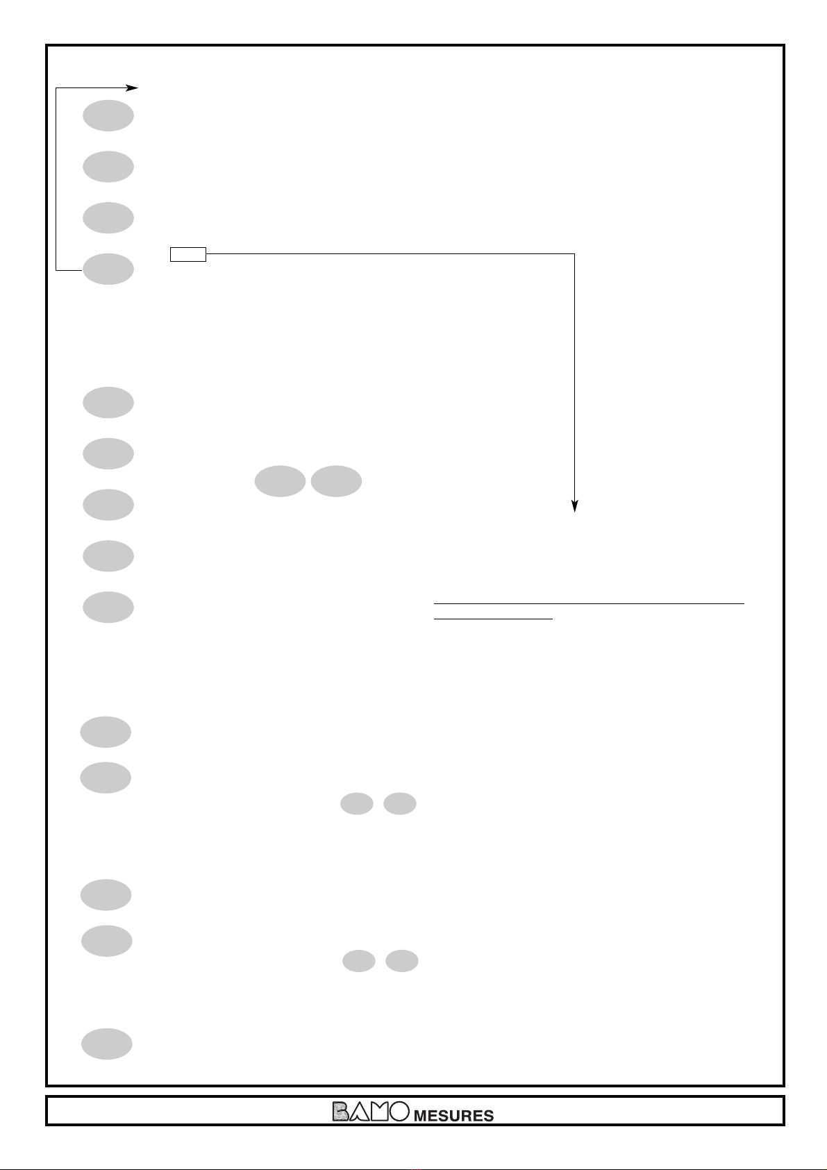
Configuration: 8 push buttons keyboard on the front - Keyword protected
Scales: 0 to 100% – or mg/L
Accuracy/measurement: ± 0.3%
Accuracy/temperature: ± 0.3°C
Probe input: Screw connectors, IP40
T° compensation: Automatic with an input for a 3 wires Pt 100 Ohm/0°C, range 0…100°C
Manually from 0 to 100°C
Relay outputs: 4 closing contacts (Silver alloy), voltage free
Thresholds: 3 programmable independent thresholds - with adjustable hysteresis 0…100%
and adjustable timer from 0 to 9999 sec
Output relay (S4) Common alarm signal for:
- Too long injection – temperature...
- over scale measurement or open loop
- Pt 100 Ohm dysfunction
- or probe cleaning function
Contact: Initial resistance 100 milliOhm as a maximum (voltage drop 6 V DC 1 A)
Rated at 831 V AC / 3 A / 277 V AC ; 90 W / 3 A / 30 V DC
Switching capacity (minimum) 100 mA, 5 V DC
(depending of switching frequency, ambient conditions, accuracy)
Mechanical lifetime (minimum) 5 x10⁶operations (180 commutation/min)
Electrical life time (minimum) 2 x10⁵(20 comm./min) [3 A, 125 V AC], [3 A, 30 V DC]
and 105(evaluated charge) for 3 A, 125 V AC
ON/OFF Regulation: Pulse time 0…9999 sec - High and low proportional bandwidth, high and low dead zones
PID Regulation: Proportionality 0…200%, - Integrant and Derivative: 0…999 second
Calibration sequence: Regulation on standby, relay outputs inhibited, analogical outputs stand on last values
Self-cleaning program: Frequency and duration settings, with regulation inhibited and analogical outputs standing on last values
Measurement output: 0/4-20 mA (maxi 600 _) proportional to measurement, galvanic insulated
T° output / PID: 0/4-20 mA (max 600 _), scaling 0…100°C, galvanic insulated
Program testing: Simulation through the menu on measurement, temperature, PID and relay outputs
Main power supply: 230 V AC / 50-60 Hz [other on request] - Consumption 10 VA
Models: Panel mounting, IP65, 72 x 144 mm, connections on screw terminal IP40
DIN Rail mounting, connections on screw terminal IP40, only for blind monitor
Wall mounting, IP65, cable glands, connections on screw terminal
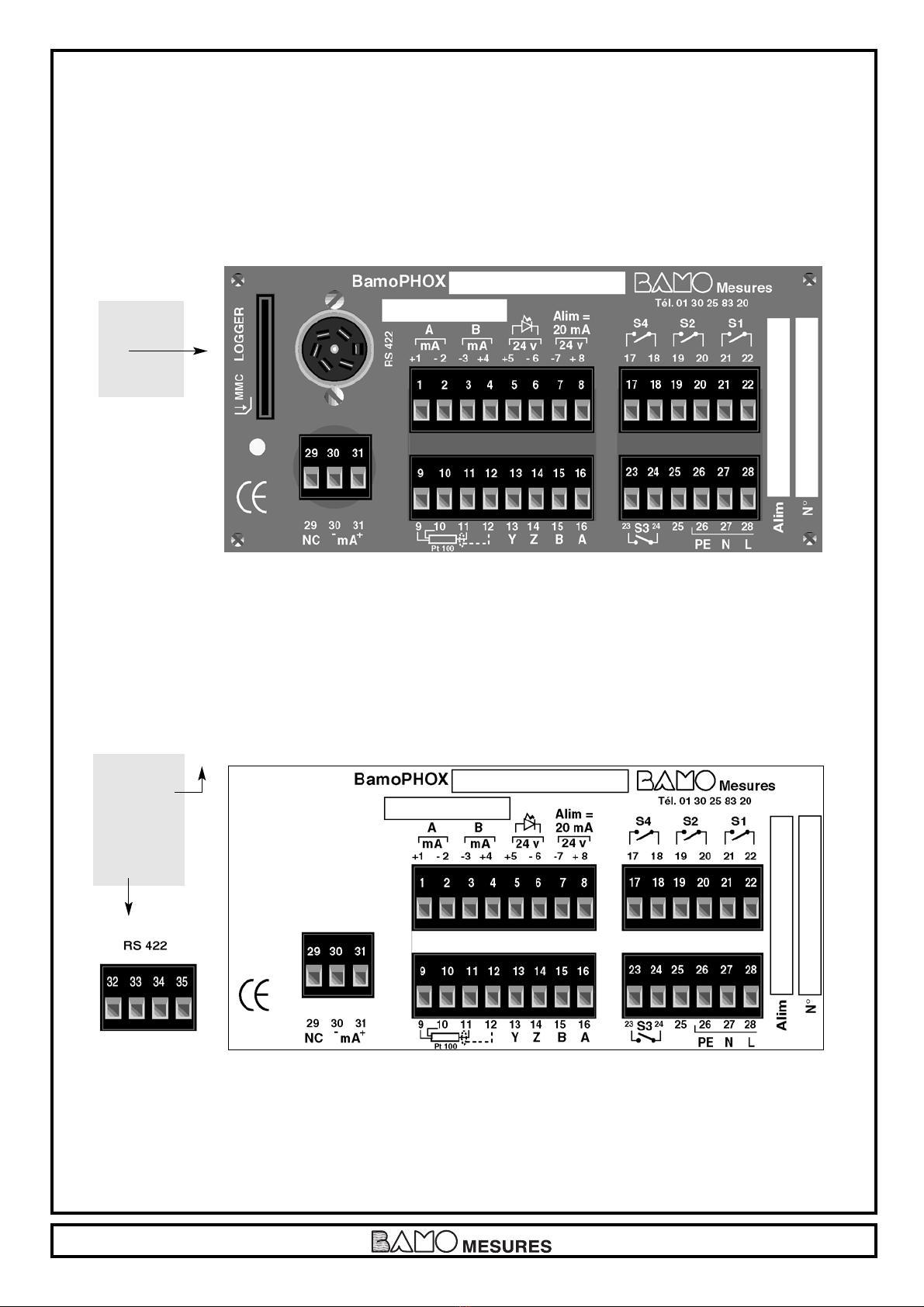
OPTION (RS 422 + Logger)
Communication: RS422 output, J-BUS link, binary slave mode, 2400 to 9600 bauds
Data Logger: Cycle average measurement record, with a programmable period,
150000 records on MMC (multi media card) / External driver necessary for reading
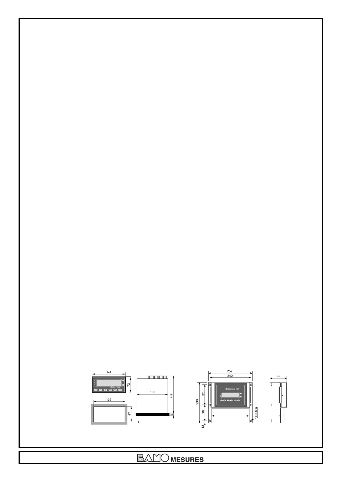
2. DIMENSIONS
Extension terminal:
identical to the panel
or wall mounting
BAMOPHOX
PANEL
Wall mounting instrument
Panel mounting instrument

Page 4
450 M1 02 B 11-10-2007
3. WIRING
PANEL MOUNTING MODEL
OPTION :
LOGGER
&
RS 422
OPTION :
LOGGER
(access by the
upper cover)
&
RS 422
WALL MOUNTING MODEL

Page 5
450 M1 02 B 11-10-2007
+ mA ouput / measurement
- mA ouput / measurement
- mA ouput / temperature
+ mA ouput / temperature
+ 24 V
To switch the regulation on stand-by
- 24 V
- 24 V
+ 24 V
Sensor power supply = 20 mA
Pt 100 Ω
Shield
Y
Z Connection to an extension terminal (blind BAMOPHOX)
B
A
S4 contact, NO, for system alarm
S2 threshold, NO contact – Measurement / Temperature
S1 threshold NO contact – Measurement / Temperature
S3 threshold NO contact – Measurement / Temperature
NOT USED
Ground
N
Power supply (N= Neutral, L= Live)
L
NC
- mA BAMOX 7200 sensor
+ mA
1
2
3
4
5
6
7
8
9
10
11
12
13
14
15
16
17
18
19
20
21
22
23
24
25
26
27
28
29
30
31
Screwing terminals
Wiring from wall or panel mounting BAMOPHOX to an Extension terminal BAMOPHOX
- Maximum length cable
500 m
- Wire specifications:
Mains cable or 4 wires shielded cable
≥ 0,25 mm2cross section
Main unit
YZBA
13 14 15 16
Extension terminal
YZBA
13 14 15 16

Page 6
450 M1 02 B 11-10-2007
4. FRONT PANEL
“ENTER” key
To change the step displayed menu.
At the last step, it comes back to the
first line.
“MENU - ” key
To move the cursor during configuration.
At the last digit, comes back on the first
one.
“MENU +” key
To go to the next menu.
Pushing simultaneously both keys
“MENU +” and “ENTER”
allows a fast return to measurement display.
“VALID” key
To save the parameters on EPROM
when it asks:
VALIDATION ?
Caution, when you press this key,
all parameters are saved.
(previous data programmation
will be overwrited).
If you are not sure of any modification,
do not press the VALID key,
To change parameters of data capture:
Numéric input increase the
flashing digit (loop 0 after 9).
Reverse the choice Yes / No,
Up/Down, 0-20 mA / 4-20 mA etc.
To go to the next display or to change a
value.
S1, S2, S3, and S4
indicate relays status:
LED lighting = contact ON
LED OFF = contact OFF
LED flashing = Timer in use
2 lines /16 alphanumeric characters
9.22 mm high - Back lighted
Key “A”
To display the parameters of upper line.
(main BAMOPHOX)
Key “B”
To display the parameters of lower line.
(Extension blind BAMOPHOX)

Page 7
450 M1 02 B 11-10-2007
SCROLLING MENU
00.00 m/L (Display during measurement)
ABOUT BAMOPHOX
CONSULTATION / MODIFICATION
MEASUREMENT PARAMETERS
ATMOSPHERIC PRESSURE
SALINITY
ADJUST ALARM 1
ADJUST ALARM 2
ADJUST ALARM 3
RELAY REGULATION
REGUL. PID
OUTPUT mA Oxygen
OUTPUT mA TEMP.
TEMPERATURE
FORCED RELAY
ADJUST ALARM
CLEANING PROBE
LANGUAGE
MENU
+
MENU
+
MENU
+
MENU
+
MENU
+
MENU
+
MENU
+
MENU
+
MENU
+
MENU
+
MENU
+
MENU
+
MENU
+
MENU
+
MENU
+
MENU
+
MENU
+
MENU
+

Page 8
450 M1 02 B 11-10-2007
ABOUT Bamophox
ABOUT BAMOPHOX
VERSION 2.04
SERIAL N°
20451 05
CONSULTATION / MODIFICATION
CONSULTATION
MODIFICATION
CODE ? 0000
CODE ? 5105
TIME : 30 mn
ENTER
ENTER
ENTER
ENTER
L
ENTER
ENTER
ENTER
MENU
+
L
L
From this mode MODIFICATION it is easy to return back to measurement for testing the relay outputs
and regulation mode.
Once in modification mode, reach measurement display and press ENTER
FORCED MEASURE
00,00 mg/l +20°C (one digit is flashing) Modify the value. Immediately the
instrument acts within the configuration (thresholds,
regulation, analog outputs ...).
When PID regulation is activated, the display shows the PID %
FORCED PID
00,00 mg/l 0,000% (one digit is flashing) Modify the value. Immediately the
instrument acts within the configuration.
To test the analog output (mA) on PID mode: the PID should be active and in MANUAL mode.
Press ENTER to cancel the test mode and to go back to the measurement mode.
L
L
ENTER
ENTER
ENTER
ENTER
ENTER
L
L
Last 4 digits (of serial number) are the key code to
access the MODIFICATION menu.
When wrong code is entered, a message "ERROR"
appears during 3 seconds.
After 30 minutes, the display returns automatically to the
measurement mode.

Page 9
450 M1 02 B 11-10-2007
MEASUREMENT PARAMETERS
DISPLAY %/ mg /I
Choose the right scale, confirm with "Enter" then save.
(OFFSET TEMPERATURE)
Enter the difference between real value
and reference temperature
OT +00,00 °C Example: Real value 22 °C
Reference 20 °C
Entry +2,00 °C
SAVING ?
ATMOSPHERIC PRESSURE
P = 1013 hPa The blinding digit has to be modified, if necessary.
Confirm with "Enter" then save.
SAVING ?
SALINITY
g/kg = 00,00 The blinding digit has to be modified, if necessary.
Confirm with "Enter" then save.
Salinity is expressed in [ g/ kg ] NaCl solution
SAVING ?
ENTER
ENTER
ENTER
VALID
ENTER
ENTER
VALID
ENTER
ENTER
VALID
L
L
L
L
L

Page 10
450 M1 02 B 11-10-2007
ADJUST ALARM 1 ADJUST ALARM 2
ALARM 1 ON/OFF
ALARM 1 MEASURE/TEMP MEASURE= Threshold against pH/mV measured value
TEMP.= Threshold against temperature measured value
ALARM 1 LOW/HIGH HIGH= Contact closes when value goes over the limit
LOW= Contact closes when the value goes under the limit
ON 00,00 mg/l / °C To close the contact S1 at this value
OFF 00,00 mg/l / °C To open the contact S1 at this value
DELAY UP ONI/OFF Delay (or no delay) before to close the contact S1
TIME 0000 SEC Delay time to close the contact S1
DELAYDOWN ON/OFF Delay (or no delay) before to open the contact S1
TIME 0000 SEC Delay time to open the contact S1
SAVING ?
ADJUST ALARM 2 ADJUST ALARM 3 please, see page 11
ALARM 2 ON/OFF
ALARM 2 MEASURE/TEMP MEASURE= Threshold against pH/mV measured value
TEMP.= Threshold against temperature measured value
ALARM 2 LOW/HIGH HIGH= Contact closes when value goes over the limit
LOW= Contact closes when the value goes under the limit
ON 00,00 mg/l / °C To close the contact S2 at this value
OFF 00,00 mg/l / °C To open the contact S2 at this value
DELAY UP ONI/OFF Delay (or no delay) before to close the contact S2
TIME 0000 SEC Delay time to close the contact S2
DELAYDOWN ON/OFF Delay (or no delay) before to open the contact S2
TIME 0000 SEC Delay time to open the contact S2
SAVING ?
L
L
L
LLLL
L
L
L
L
L
L
ENTER
ENTER
ENTER
ENTER
ENTER
ENTER
ENTER
ENTER
ENTER
ENTER
VALID
MENU
+
L
L
L
L L LL
L
L
L
L
L
L
ENTER
ENTER
ENTER
ENTER
ENTER
ENTER
ENTER
ENTER
ENTER
ENTER
VALID
MENU
+

Page 11
450 M1 02 B 11-10-2007
ADJUST ALARM 3 RELAY REGULATION please, see page 12
ALARM 3 ON/OFF
ALARM 3 MEASURE/TEMP MEASURE= Threshold against pH/mV measured value
TEMP.= Threshold against temperature measured value
ALARM 3 LOW/HIGH HIGH= Contact closes when value goes over the limit
LOW= Contact closes when the value goes under the limit
ON 00,00 mg/l / °C To close the contact S3 at this value
OFF 00,00 mg/l / °C To open the contact S3 at this value
DELAY UP ONI/OFF Delay (or no delay) before to close the contact S3
TIME 0000 SEC Delay time to close the contact S3
DELAY DOWN ON/OFF Delay (or no delay) before to open the contact S3
TIME 0000 SEC Delay time to open the contact S3
SAVING ?
L
L
L
L L LL
L
L
L
L
L
L
ENTER
ENTER
ENTER
ENTER
ENTER
ENTER
ENTER
ENTER
ENTER
ENTER
VALID
MENU
+

Page 12
450 M1 02 B 11-10-2007
Measurement
Highest dead zone
High BANDWITH (HIGH PB)
Low BANDWITH (LOW PB)
Time
Highest limit BW
Lowest limit BW
Set point
Lowest dead zone
Caution: On S1 you set up the lowest value for proportional bandwith and respectively S2 for the highest value.
RELAY REGULATION REGUL. PID Please see page 13
ON/OFF MODE REGUL. PID
REGUL ON/OFF
SET VAL. 00,00 mg/l Set point
T. CYCLE 0000 SEC Cycle time
Highest limit for
HIGH PB 00,00 mg/l proportional bandwith
Lowest value
LOW PB 00,00 mg/l for dead zone
Highest value
H IGH DZ 00,00 mg/l for dead zone
Lowest value
LOW DZ 00,00 mg/l for dead zone
SAVING ?
L
L L L L LL
L
L
L
L
L
L
ENTER
ENTERENTER
ENTERENTER
ENTER
ENTER
ENTER
ENTER
ENTER
ENTER
MENU
+
Indicates when S1 or S2 are “ON”
Back to “ADJUST ALARM” to switch
OFF S1 or S2
Indicates when “REGUL. PID” is
operating
Back to “REGUL. PID” menu
to switch it OFF
VALID
Set point
High limit
Low limit
Time
Measurement
Non active S1 "ON"
Cycle time
Dead zone
S2 "ON"

Page 13
450 M1 02 B 11-10-2007
Regulation Gain Ti(s) Td(s)
PID 1,2 x T/t 2 x t 0,5 x t
PI 0,9 x T/t 3,3 x t 0
P T/t 9999 0
ADJUST PID PARAMETERS
In order to determinate the setup values for PID regulation, we recommend to use the Ziegler-Nichols open loop method
Proceed as following:
- Connect a recorder to the analogic measurement output or write the reading measurement values for then to draw the graph f(time)
- Switch on the PID regulation in MANUAL mode
- Reach to and keep close the measurement value to the set point, adjusting the PID output
- Apply on ΔCde a step of 10 % (for instance) on the analogic output (Cde).
Example: if the value is 30,00 %, apply 40,00 %
- Note on the graph the corresponding timing.
- Determinate on this graph both t ant T:
t = delay of response
T = Time corresponding to the same variation in % of measurement (Δm) and the analogic output (ΔCde), Δm = ΔCde.
This value may be found out on the slope.
- Modify the PID parameters as following:
REGUL PID Output mA Oxygen Please see page 14
This operating mode allows a PID regulation with
an analogic output 0/20 or 4/20 mA
REGUL ON/OFF To switch ON or OFF the regulation mode
REGUL AUTO/MANU MANU=MANUAL to be able to check the relays output
SET VAL 00,00 mg/l Set point value
GAIN : 0,000 Gain setup (see also ADJUST PID PARAMETERS)
T.i : 0050 Sec Integrant setup
Td : 0012 Sec Derivative setup
ACTION: DIRECT/REVERSE
OUTPUT 4/20 mA /0/20 mA
SAVING ?
L
L
L
L L L
L
L L
L
L
L
ENTER
ENTER
ENTER
ENTER
ENTER
ENTER
ENTER
VALID
MENU
+
To switch the PID regulation on stand-by, please input 24 V= 20 mA on terminals 5(+) and 6(-).

Page 14
450 M1 02 B 11-10-2007
Output mA Oxygen Output mA TEMP.
Measurement signal copy on the analog output
HIGHER 00,00 mg/l Value corresponding to 20,00 mA
LOWER 00,00 mg/l Value corresponding to 00,00 or 04,00 mA
OUTPUT 4/20 mA /0/20 mA Output type
SAVING ?
L
L
L
L L
ENTER
ENTER
ENTER
ENTER
VALID
MENU
+
Output mA TEMP. TEMPERATURE
HIGHER 0000 °C Value corresponding to 20,00 mA
LOWER 0000 °C Value corresponding to 00,00 or 04,00 mA
OUTPUT 4/20 mA /0/20 mA Output type
SAVING ?
L
L
L
LL
ENTER
ENTER
ENTER
ENTER
VALID
MENU
+
TEMPERATURE CALIBRATION Please see page 15
AUTO: A Pt 100 probe should be connected
MEASURE : AUTO / MANUAL MANUAL: Without Pt 100 probe
Manualy entered temperature value
FLUIDE T. + 0000 °C (MANUAL mode)
SAVING ?
L
L
L
ENTER
ENTER
ENTER
VALID
MENU
+
Caution: If PID regulation is active, this step menu would not appears

Page 15
450 M1 02 B 11-10-2007
CALIBRATION FORCED RELAYS Please see page 16
SOL ZERO Immerse the sensor in a solution of 17 g of sodium sulphite
anhydrous (Na2SO3) in distilled water.
See also the probe manual.
PROBE IN AIR Let the probe in the air, moving it to have a better exchange.
See also the probe manual
COEF 0000 Display of the gain
The value should be close to the full-scale value
ERROR Error message appears when the gain value is too high
or too small.
When Error message occurs:
- press "MENU" to be back to CONFIGURATION
Proceed to a new calibration sequence.
If the ERROR message appears again:
- cancel the calibration sequence, go back to measurement
- check the dirtiness of the sensor
- replace the membrane if necessary
See also the probe manual
If the error message disappears:
95 % When gain value is correct (from 70% to 110%)
Confirm the calibration sequence with "ENTER"
DELAY 0000 Sec
Choose the stand-by period, all regulation and
measurements are on stand-by (same values blocked as
they were beginning the calibration) during this timing
SAVING ?
L
L
ENTER
ENTER
ENTER
ENTER
ENTER
VALID
MENU
+
MENU

Page 16
450 M1 02 B 11-10-2007
CLEANING PROBE LANGUAGE
(Contact S4)
In order to protect the regulation, all measurements are on
stand-by during the cleaning process (plus a delay before
to restart the operating mode).
CLEANING YES / NO
PERIOD 0000 Sec Set up the time after witch a cleaning sequence will begin
TIME 0000 Sec Cleaning time
DELAY 0000 Sec Delay after cleaning, before to restart the regulation mode
SAVING ?
L
L
L
L L
L
L
ENTER
ENTER
ENTER
ENTER
ENTER
VALID
MENU
+
FORCED RELAY ADJUST ALARM
ALARM 1 ON/OFF
ALARM 2 ON/OFF
Diagnostic mode to test the threshold configurations
ALARM 3 ON/OFF
ALARM 4 ON/OFF
L
L
L
L
ENTER
ENTER
ENTER
ENTER
VALID
MENU
+
ADJUST ALARM LANGUAGE
When in use the S4 contact is active.
This mode allows to detect a malfunction on S1
and S2 contacts ; an overtime contact could be set up.
WITH / WITHOUT ALARM
TIME. S1 0005 Sec
Overtiming on S1 closed contact
(maximum time for active relay)
TIME. S2 0000 Sec
Overtiming on S2 closed contact
(maximum time for active relay)
SAVING ?
L
L
L
LL
ENTER
ENTER
ENTER
ENTER
VALID
MENU
+
LANGUAGE Back to display
ENGLISH, ITALIAN, FRENCH
SAVING ?
L
ENTER
ENTER
VALID
MENU
+
This manual suits for next models
1
Table of contents
Other Bamo Monitor manuals