Bamo BAMOPHOX 194 User manual

%*
<?5@><5B@93A97=1;<>=9B>@
%'(!'/
13-12-2013 194 M1 01
INSTRUCTIONS MANUAL
%'(!'/
<?5@><5B@93A5=A>@AA97=1;<>=9B>@

(175
% 12-13-2013
Amperometric signal monitor
%'(!'/
(Technical information and Manual for LOGGER /RS422 version are on a specific document)
Table of contents
Page
1. TECHNICAL SPECI ICATIONS 3
2. DIMENSIONS 3
3. WIRING 4
4. RONT PANEL 7
SCROLLING MENU 8
ABOUT BAMOPHOX 9
CONSULTING / MODI YING 9
TESTING RELAY OUTPUTS 9
SENSOR CON IGURATION 10
ADJUSTING THRESHOLD 1 11
ADJUSTING THRESHOLD 2 11
ADJUSTING THRESHOLD 3 12
ON/O REGULATION 13
PID REGULATION 15
ANALOG OUTPUT 4-20 mA OR MEASUREMENT SIGNAL 17
ANALOG OUTPUT 4-20 mA OR TEMPERATURE 17
TEMPERATURE CON IGURATION 17
SENSOR CALIBRATION 18
TESTING REGULATION MODE 19
CON IGURING ALARM CONTACT 19
LANGUAGE 19

(175
% 12-13-2013
+!&"$+,)*
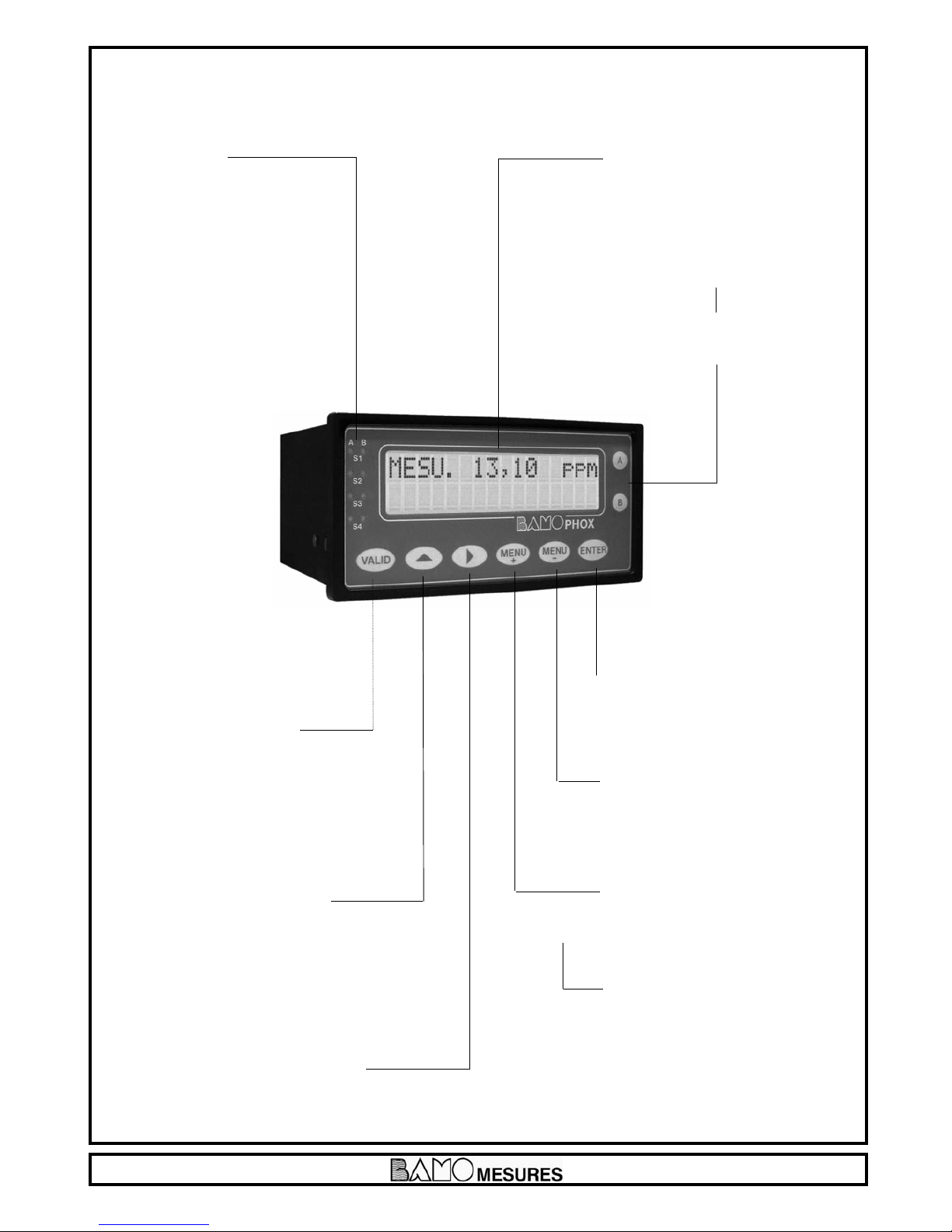
Displayed parameters: Measured values - Configuration Menu - Temperature
Display: Back lighted - 2 lines of 16 alphanumerical characters ; 9 mm high
Indication: LED alarms status
Configuration: 8 push buttons keyboard on front board - Keyword protected
Sensor input: or amperometric sensors 4-20 mA (2 wire technique) or 0/-2 V (4 wire technique)
Scales: Configuration within the sensor in use, from 0.001 to 9999 ppm or g/L
Accuracy: depending of the sensor in use (see technical features of sensor)
low control Input for inductive sensor type NPN (making contact if present flow rate)
Temperature: ±3.0 °C
Relay outputs: 4 contacts (Silver alloy), voltage free
Thresholds: 3 programmable independent thresholds - with adjustable hysteresis 0…100 %
threshold S3 available in copy of external input signal (example: flow sensor)
and adjustable, timer from 0 to 9999 sec
Output relay (S4) Common alarm signal for: Too long injection, Temperature out of range etc.
Contact: Initial resistance 0.1 Ohm as a maximum (voltage drop 6 V DC 1 A)
Rated at 831 V AC / 3 A / 277 V AC ; 90 W / 3 A / 30 V DC
Switching capacity (minimum) 100 mA, 5 V DC
(depending of switching frequency, ambient conditions, accuracy)
Mechanical life time (minimum) 5 x10⁶operations (180 commutation /min)
Electrical life time (minimum) 2 x10⁵(20 comm./min) [3 A, 125 V AC], [3 A, 30 V DC]
and 105(evaluated charge) for 3 A, 125 V AC
ON/O Regulation: Pulse time 0…9999 sec - High and low proportional bandwidth, high and low dead zone.
Calibration sequence: Regulation on standby, relay outputs inhibited, analogical outputs stand on last values
Measurement output: 0/4-20 mA (maxi 600 Ohm) proportional to measurement, galvanic insulated
Temperature output: 0/4-20 mA (max 600 Ohm), scaling -20 to +160°C, galvanic insulated
Program Testing: simulation through the menu on measurement, temperature, and relay outputs
Main power supply: 230 V AC / 50-60 Hz (other on request) - Consumption 10 VA
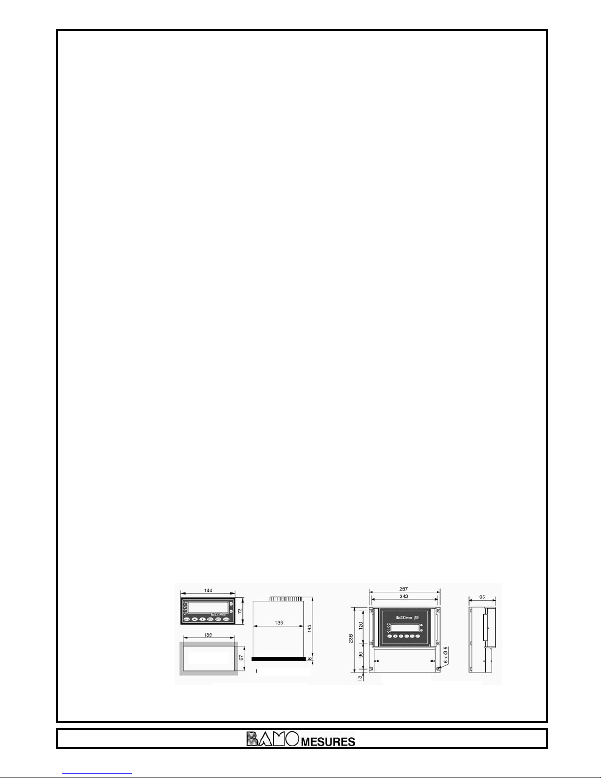
Models: Panel mounting, IP65, 72 x 144 mm, connections on screw terminal IP40
Idem DIN Rail mounting, only for blind monitor
Wall mounting, IP65, cable glands, connections on screw terminal
'(+"'&)*$>775@
Communication: RS422 output, J-BUS link, binary slave mode, 2400 to 9600 bauds
Data Logger: Cycle average measurement record, with a programmable period,
150 000 records on memory card / External driver necessary for reading
"%&*"'&*
FB5=A9>=B5@<9=1;
identical to the panel
or wall mounting
PANEL
.1;;<>C=B9=79=AB@C<5=B
(1=5;<>C=B9=79=AB@C<5=B

(175
% 12-13-2013
.$$%',&+"& "&*+),%&+
.")"&
'(+"'&
LOGGER
&
RS 422
'(+"'&
LOGGER
(access by
upper cover)
&
RS 422
(&$%',&+"& "&*+),%&+
- - -
Signal input
Signal input
- - -

(175
% 12-13-2013
+ mA ouput / measurement
- mA ouput / measurement
- mA ouput / temperature or Regulation PID
+ mA ouput / temperature or Regulation PID
+ 24 V
- 24 V
- 24 V
+ 24 V
Pt 100 Ω
Shield
Y
Z Connection to an extension terminal (blind BAMOPHOX)
B
A
S4 contact, NO, alarm on temperature or over range
S2 threshold, NO contact – Measurement / Temperature
S1 threshold NO contact – Measurement / Temperature
S3 threshold NO contact – Measurement / Temperature / External sensor
NOT USED
Ground
N
%19=?>E5@AC??;G&&5CB@1;$$9=5
L
V-
V+
0V
E
1
2
3
4
5
6
7
8
9
10
11
12
13
14
15
16
17
18
19
20
21
22
23
24
25
26
27
28
29
30
31
36
Screwing terminals
.9@9=76@><E1;;>@?1=5;<>C=B9=7%'(!'/B>1=FB5=A9>=B5@<9=1;%'(!'/
- Maximum length cable:
500 m
- Wire specifications:
Mains cable or 4 wires
shielded cable
≥ 0,25 mm2cross section
%19=C=9B
YZBA
13 14 15 16
FB5=A9>=B5@<9=1;
YZBA
13 14 15 16
*97=1;9=?CB
low controller connection

(175
% 12-13-2013
TERMINAL FOR SENSOR CONNECTION
Load resistor
supplied with
the BAMOPHOX 194
4-20 mA sensor 0
0 to -2000 mV sensor
TERMINAL FOR SENSOR CONNECTION
+
+
–
Flow rate sensor (194 832)
NPN type normally open
Brown = +
Blue = –
Black = output
Alim =
24 V
Shunt
Black
Blue
Brown
(194 831)

(175
% 12-13-2013
)'&+(&$
I&+)J key
To change the step displayed menu.
At the last step, it comes back to the
first line.
I%&,Jkey
To move the cursor during configuration.
At the last digit, comes back on the first one.
I%&,Jkey
To go to the next menu.
Pushing simultaneously both keys
“%&,J and I&+)J
allows a fast return to measurement display.
I-$"Jkey
To save the parameters on EPROM
when it asks:
*-"&
Caution, when you press this key,
all parameters are saved.
(previous data programmation
will be overwrited).
If you are not sure of any modification,
do not press the VALID key,
To change parameters of data capture:
Numéric input increase the
flashing digit (loop 0 after 9).
Reverse the choice Yes / No,
Up/Down, 0-20 mA / 4-20 mA etc.
To go to the next display or to change a value.
* * *1=4*
indicate relays status:
LED lighting = contact ON
LED O = contact O
LED flashing = Timer in use
2 lines /16 alphanumeric characters
9.22 mm high - Back lighted
Key IJ
To display the parameters of upper line.
(main BAMOPHOX)
Key IJ
To display the parameters of lower line.
(Extension blind BAMOPHOX)

(175
% 12-13-2013
" ()*&++"'&+"$%&+,%&,
%*,??< H
ABOUT BAMOPHOX
CONSULTATION / MODI ICATION
SENSOR CON IGURATION
ADJUST ALARM 1
ADJUST ALARM 2
ADJUST ALARM 3
RELAY REGULATION
REGUL. PID
OUTPUT mA MES
OUTPUT mA TEMP.
TEMPERATURE
SENSOR CALIBRATION
ORCED RELAY
ADJUST ALARM
CLOCK
RECORDING TIME
LANGUAGE
%&,
%&,
%&,
%&,
%&,
%&,
%&,
%&,
%&,
%&,
%&,
%&,
%&,
%&,
%&,
%&,
%&,
%&,
&+) Press &+) to change the display
from MEASUREMENT
or TEMPERATURE

(175
% 12-13-2013
',+1<>?8>F
ABOUT BAMOPHOX
VERSION 2.04
SERIAL N°
20451 05
'&*,$++"'&%'""+"'&
CONSULTATION
MODI ICATION
CODE ? 0000
CODE ? 5105
TIME : 30 mn
&+)
&+)
&+)
&+)
▲
&+)
&+)
&+)
%&,
▲
▲
@><B89A<>45%'""+"'&6>@B5AB9=7B85@5;1G>CB?CBA1=4@57C;1B9>=<>45@5138<51AC@5<5=B
49A?;1G;1ABA3@55=1=4?@5AA&+)
ORCED MEASURE
00.00 ppm (one digit is flashing) Modify the value. Immediately the
instrument acts within the configuration (thresholds,
regulation, analog outputs ...).
.85=("@57C;1B9>=9A13B9D1B54B8549A?;1GA8>EAB85("
ORCED PID
00.00 ppm 00.00 % (One digit is flashing) Modify the value. Immediately the
instrument acts within the configuration.
To test the analog output (mA) on PID mode: the PID should be active and in MANUAL mode.
Press ENTER to cancel the test mode and to go back to the measurement mode.
▲
▲
&+)
&+)
&+)
&+)
&+)
▲
▲
The last 4 digits (of serial number) are the key code to
access to the MODI ICATION menu.
When wrong code is entered, a message "ERROR"
appears during 3 seconds
After 30 minutes, the display returns automatically to the
measurement mode

(175
% 12-13-2013
*&*')'&" ,)+"'&
PRODUCT Select corresponding sensor for: free chlorine, total
chlorine, chlorine dioxide, ozone, hydrogen peroxide,
peracetic acid
UNIT Choose between: ppm / g/L
x-x.xxx ppm Decimal point (coma) position
SCALE
MAXI: 00.00 Maximal value of the measuring scale
SENSOR mA or mV
SAVING ?
&+)
&+)
&+)
&+)
&+)
&+)
&+)
&+)
%&,
▲ ▲
▲
▲
▲
▲
Next menu: ADJUST ALARM 1
"&+)',+"'&+'%'(!'/'&+)'$
Before setting up alarms or way of control, the running way has to be defined.
1<>?8>F1;;>EAG>CB8@55E1GA
lSingle alarms with alarms S1 and/or S2
lRelay regulation with set point, proportional bands and dead zones
lP.I.D. regulation with the 4-20 mA signal
There is a specificity of alarm 3 in Bamophox 194. It can be setup for an external sensor. Signal is coming from an
inductive flow rate sensor type NPN. This sensor is mounted in the flow cell.
*5=A>@A97=1;5=B5@9=71<>?8>F13B9D1B5A>@4513B9D1B5A*1;1@<
lIn case of flow rate, alarm 3 is closed (active)
lIn miss of flow rate, alarm 3 is open (inactive)
+89AA97=1;E9;;13B>=B85@57C;1B9>=;9:56>;;>E9=7
lIf the user is running with single alarms, there will be no more action on alarms S1 and/or S2.
However user can wire alarms S1 and S3 in serial way in the aim of securing the injection (if alarm 1 deals with the
reagent injection)
lIf the user is running in relay regulation, alarms S1 and S2 become open (inactive).
The regulation is inhibited.
lIf the user is running P.I.D regulation, 4-20mA signal become locked.

(175
% 12-13-2013
#,*+$)%
ALARM 1 '&'
ALARM 1 %*,)+%( %*,)= Threshold against measured value
+%(= Threshold against temperature measured value
$)%$'.!" ! !" != Contact closes when value goes over the limit
$'.= Contact closes when the value goes under the limit
ON ppm To close the contact S1 at this value
O ppm To open the contact S1 at this value
DELAY UP '&"' Delay (or no delay) before to close the contact S1
TIME SEC Delay time to close the contact S1
DELAY DOWN '&' Delay (or no delay) before to open the contact S1
TIME SEC Delay time to open the contact S1
*-"&
#,*+$)%
ALARM 2 '&'
ALARM 2 %*,)+%( %*,)= Threshold against measured value
+%(= Threshold against temperature measured value
$)%$'.!" ! !" != Contact closes when value goes over the limit
$'.= Contact closes when the value goes under the limit
ON ppm To close the contact S2 at this value
O ppm To open the contact S2 at this value
DELAY UP '&"' Delay (or no delay) before to close the contact S2
TIME SEC Delay time to close the contact S2
DELAYDOWN '&' Delay (or no delay) before to open the contact S2
TIME SEC Delay time to open the contact S2
*-"&
▲
▲
▲
▲ ▲ ▲ ▲
▲
▲
▲
▲
▲
▲
&+)
&+)
&+)
&+)
&+)
&+)
&+)
&+)
&+)
&+)
-$"
▲
▲
▲
▲ ▲ ▲ ▲
▲
▲
▲
▲
▲
▲
&+)
&+)
&+)
&+)
&+)
&+)
&+)
&+)
&+)
&+)
-$"
%&,
Next menu: ADJUST ALARM 2
%&,
Next menu: ADJUST ALARM 3

(175
% 12-13-2013
#,*+$)%
ALARM 3 '&'
EXTERN &'0* &'= set up (ALARM 3 MEASURE/TEMP)
0*= flow rate sensor wired
*-"&
ALARM 3 %*,)+%( %*,)= Threshold against measured value
+%(= Threshold against temperature measured value
$)%$'.!" ! !" != Contact closes when value goes over the limit
$'.= Contact closes when the value goes under the limit
ON ppm To close the contact S3 at this value
O ppm To open the contact S3 at this value
DELAY UP '&"' Delay (or no delay) before to close the contact S3
TIME SEC Delay time to close the contact S3
DELAYDOWN '&' Delay (or no delay) before to open the contact S3
TIME SEC Delay time to open the contact S3
*-"&
%&,
Next menu: RELA REGULATION
▲
▲
▲ ▲ ▲ ▲
▲
▲
▲
▲
▲
▲
&+)
&+)
&+)
&+)
&+)
&+)
&+)
&+)
&+)
&+)
-$"
-$"
-$"
▲
▲

(175
% 12-13-2013
)$0) ,$+"'&
'&'%' ) ,$("
REGUL '&'
SET VAL. ppm Set point
T. CYCLE SEC Cycle time
Highest limit for
HIGH PB ppm proportional bandwith
Lowest value for
LOW PB ppm proportional bandwith
Highest value
H IGH DZ ppm for dead zone
Lowest value
LOW DZ ppm for dead zone
SAVING ?
▲
▲ ▲ ▲ ▲ ▲ ▲
▲
▲
▲
▲
▲
▲
&+)
&+)&+)
&+)&+)
&+)
&+)
&+)
&+)
&+)
&+)
Indicates when S1 or S2 are “ON”
Back to “ADJUST ALARM” to switch
O S1 or S2
Indicates when “REGUL. PID” is
operating
Back to “REGUL. PID” menu
to switch it O
-$"
%&,
Next menu: REGUL PID

(175
% 12-13-2013
F1<?;5
With process configuration:
- Set point: 1.5 ppm
- High dead zone: 0.4 ppm between 1.5 and 1.9 ppm
- Low dead zone : 0.1 ppm between 1.4 and 1.5 ppm
- High BANDWIDTH: 3.5 ppm (that is a limit of 5 ppm for the maximum)
- Low BANDWIDTH: 0.5 ppm (that is a limit of 1 ppm for the minimum)
- Over the highest limit (>5 ppm), S2 is “ON” for a continuous injection (contact S2 is closed)
- Under the lowest limit (<1 ppm), S1 is “ON” for a continuous injection (contact S1 is closed)
- Inside the dead zone (between 1.4 & 1.9 ppm), S1 and S2 are “O ”, no injection at all (contacts S1 and S2 are opened)
- If the measurement value is between the dead zone and the highest limit (between 1.9 & 5 ppm)
or between the dead zone and the lowest limit (between 1.0 & 1.4 ppm), the contact S1 or S2 are “ON” only for a time
proportional to the step between measurement and desired value.
,+"'& The minimum closing time of a relay is 1 second.
If the measurement M=1.42 and if the cycle time is 10 seconds,
the closing contact time is:
Closing contact time /S1=
Low proportional BANDWIDTH
Cycle time x (measure - set point)
10 x (1.5-1.42)
0,4 = 2 sec

(175
% 12-13-2013
)57C;1B9>= 19= +9A +4A
PID 1.2 x T/t 2 x t 0.55 x t
PI 0.9 x T/t 3.3 x t 0
P T/t 9999 0
#,*+("()%+)*
In order to determinate the setup values for PID regulation, we recommend to use the Ziegler-Nichols open loop method
(@>35541A6>;;>E9=7
- Connect a recorder to the analogic measurement output or write the reading measurement values for then to draw the graph f(time)
- Switch on the PID regulation in MANUAL mode
- Reach to and keep close the measurement value to the set point, adjusting the PID output
- Apply on ∆Cde a step of 10 % (for instance) on the analog output (Cde).
F1<?;5 if the value is 30%, apply 40%
- Note on the graph the corresponding timing T0
- ind on the graph both times t ant T such as ∆m= ∆Cde:
t = delay of response
T = Time corresponding to the same variation in % of measurement (∆m) and the analog output (∆Cde), ∆m= ∆Cde.
This value may be found out on the slope.
- Modify the PID parameters as following:
) ,$("
+89A>?5@1B9=7<>451;;>EA1("@57C;1B9>=E9B81=1=1;>793
>CB?CB>@<(terminals 3 and 4). +89A>CB?CB9A=>
<>@51D19;12;56>@B5<?5@1BC@5>CB?CB
REGUL '&' To switch ON or O the regulation mode
REGUL ,+'%&, MANU=MANUAL to be able to check the relays output
SET VAL ??< Set point value
GAIN : Gain setup (see below ADJUST PID PARAMETERS)
T.i : Sec Integral timing
Td : Sec Derivative timing
ACTION: ")+)-)* Direct action or Reverse action for PID regulation
OUTPUT </< Signal output
SAVING ?
▲
▲
▲
▲ ▲ ▲
▲
▲ ▲
▲
▲
▲
&+)
&+)
&+)
&+)
&+)
&+)
&+)
-$"
+>AE9B38B85("@57C;1B9>=>=AB1=42G9=?CB-<>=B5@<9=1;A1=4
%&,
Next menu: Output mA
MEASUREMENT

(175
% 12-13-2013
ppm measurement

(175
% 12-13-2013
'CB?CB<%*,)%&+
Measurement signal copy on the analog output
HIGHER ppm Value corresponding to 20,00 mA
LOWER ppm Value corresponding to 0.00 or 04,00 mA
OUTPUT </< Output type
SAVING ?
▲
▲
▲
▲ ▲
&+)
&+)
&+)
&+)
-$"
'CB?CB<+%(
HIGHER °C Value corresponding to 20.00 mA
LOWER °C Value corresponding to 00.00 or 04.00 mA
OUTPUT </< Output type
SAVING ?
▲
▲
▲
▲ ▲
&+)
&+)
&+)
&+)
-$"
+%()+,)
,+': A Pt 100 probe should be connected
MEASURE : ,+'%&,$ %&,$: Without Pt 100 probe
Manualy entered temperature value
LUIDE T. + °C (In MANUAL Mode only)
SAVING ?
▲
▲
▲
&+)
&+)
&+)
-$"
1CB9>=.85=("@57C;1B9>=9A13B9D5B89AAB5?<5=C4>5A=>B1??51@A
%&,
Next menu: Output mA TEMP.
%&,
Next menu: TEMPERATURE
%&,
Next menu: SENSOR CALIBRATION
+>AE9B38B85("@57C;1B9>=>=AB1=42G
9=?CB-<>=B5@<9=1;A1=4

(175
% 12-13-2013
$+)'$")+"'&
▲
▲
▲
▲
▲
▲
&+)
&+)
&+)
&+)
&+)
-$"
,+"'&+5<?5@1BC@53><?5=A1B9>=
A5BC?B859=AB@C<5=B>=%&,$<>451BH
During calibration in mode “MODI ICATION”, measurement
value is on stand-by on the last reading value, the regulation is on
stand-by. A delay after ending the calibration allows a restart of
the complete system before to automatically restart the regulation
mode.
Choose &', the sensor is a non adjusting zero required
&' will send to the display “*$'(”
Choose 0* to proceed to a sensor calibration
&' will send to the display “$0”
The calibration measuring value is locked when the submenu
‘’STANDARD’’ is displayed. Proceed at the same time to a test to
know the standard value according to the sensor in use.
Enter the result value
(For good calibration, value has to be as closed as the sensor
full range)
Sensor gain is displayed.
,+"'&
"6B85A;>?5D1;C59A>@ do not valid this calibration
step. Check the dirtiness of the sensor; do a maintenance on it
and proceed to a second calibration.
"6B85A;>?5D1;C59A25BE55=1=4proceed to a second
test to confirm the previous test
Set up the time during the measuring and status regulation
previous to the calibration, will be displayed after saving the
calibration.
,+"'&+5<?5@1BC@53><?5=A1B9>=961(+?@>259A
3>==53B54@5A5BB85B5<?5@1BC@53><?5=A1B9>=9=,+'
STANDARD. ZERO 0*&'
STANDARD. SLOPE 0*&'
STANDARD ppm
SLOPE xxx,x %
DELAY 0015 Sec
SAVING ?
%&,
Next menu: FORCED RELA

(175
% 12-13-2013
')K)$0
ALARM 1 ON / O
ALARM 2 ON / O
Diagnostic mode to test manually the threshold configurations
ALARM 3 ON / O
ALARM 4 ON / O
▲
▲
▲
▲
&+)
&+)
&+)
&+)
&+)
#,*+$)%
&$*>@"*$*B85*@5;1G
"=31A5>6<1;6C=3B9>=>6B853>=B@>;@5;1G
This mode allows detecting a malfunction on S1
and S2 contacts ; an overtime contact could be set up.
."+!.!"+!',+ALARM
TMAX. S1 Sec
Over timing on S1 closed contact
(maximum time for active relay)
TMAX. S2 Sec
Over timing on S2 closed contact
(maximum time for active relay)
SAVING ?
▲
▲
▲
▲ ▲
&+)
&+)
&+)
&+)
-$"
$& ,
RENCH / ENGLISH / ITALIAN
GERMAN
SAVING ?
▲
&+)
&+)
-$"
&'+
To complete the configuration
of a %'(!'/$>775@ (option)
follow the corresponding manual.
%&,
Next menu: ADJUST ALARM
%&,
Next menu: LANGUAGE or CLOCK
Table of contents
Other Bamo Monitor manuals