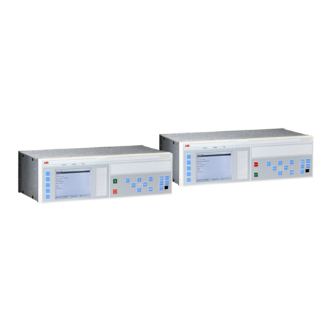
ABB ITH-T Series Guide

I
.
L
.
41
-
771.2
INSTALLATION
*
OPERATION
•
MAINTENANCE
INSTRUCTIONS
ABB
ASEA
BROWN
BOVERI
TYPE
ITH
-
T
RELAY
(
PRELIMINARY
EDITION
)
CAUTION
down
on
a
vertical
guide
rod
in
the
center
of
the
solenoid
coil
.
The
plunger
assembly
consists
of
a
bushing
which
is
threaded
on
the
moving
plunger
and
locked
in
place
by
a
nut
,
and
a
silver
disc
which
rests
on
a
helical
compres
-
sion
spring
at
the
lower
end
of
the
plunger
.
The
guide
rod
is
fastened
to
the
stationary
core
which
in
turn
is
held
in
place
by
the
insulating
plate
on
which
the
stationary
contacts
are
mounted
.
The
stationary
core
consists
of
two
steel
sections
separated
by
a
non
-
magnetic
ring
.
This
non
magnetic
ring
provides
an
air
gap
in
which
the
plunger
steel
floats
.
When
the
coil
is
energized
,
the
plunger
assembly
moves
upward
carrying
the
silver
disc
which
bridges
three
spring
type
conical
shaped
station
-
ary
contacts
.
In
this
position
,
the
helical
spring
is
com
-
pressed
and
the
plunger
is
free
to
move
while
the
contact
disc
remains
stationary
.
Thus
,
ac
vibrations
of
the
plunger
assembly
are
prevented
from
causing
contact
chattering
.
A
Micarta
disc
which
acts
as
a
shield
for
the
contact
plate
,
screws
on
the
bottom
of
the
guide
rod
and
is
locked
into
position
by
a
small
nut
.
The
adjustable
screw
in
the
top
of
the
frame
provides
the
principal
means
for
adjusting
the
current
operating
values
.
Before
putting
relays
into
service
,
remove
all
blocking
which
may
have
been
inserted
for
the
pur
-
pose
of
securing
the
parts
during
shipment
,
make
sure
that
all
moving
parts
operate
freely
,
inspect
the
contacts
to
see
that
they
are
clean
and
close
prop
-
erly
,
and
operate
the
relay
to
check
the
setting
and
electrical
connections
.
1
.
APPLICATION
This
3
-
phase
relay
with
individual
phase
indication
is
intended
for
use
in
applications
where
a
nondirectional
high
dropout
ratio
overcurrent
unit
is
required
and
a
short
time
delay
is
needed
to
prevent
operation
on
such
things
as
transformer
inrush
current
or
dc
offset
cur
-
rent
.
This
relay
may
be
used
on
the
supply
side
of
a
transformer
to
provide
improved
sensitivity
and
still
coordinate
on
a
time
basis
with
downstream
devices
.
3.2
Contactor
Switch
2
.
CONTENT
The
dc
contactor
switch
in
the
relay
is
a
small
sole
-
noid
type
switch
.
A
cylindrical
plunger
with
a
silver
disc
mounted
on
its
lower
end
moves
in
the
core
of
the
solenoid
.
The
relay
consists
of
three
high
drop
out
instantane
-
ous
units
with
an
equal
number
of
operation
indicators
,
one
contactor
switch
,
and
a
timing
circuit
.
As
the
plunger
travels
upward
,
the
disc
bridges
three
silver
stationary
contacts
.
The
coil
is
in
series
with
the
main
contacts
of
the
relay
and
with
the
trip
coil
of
the
breaker
.
When
the
relay
contacts
close
,
the
coil
be
-
comes
energized
and
closes
the
switch
contacts
.
This
shunts
the
main
relay
contacts
,
thereby
relieving
them
of
the
duty
of
carrying
tripping
current
.
These
contacts
3
.
CONSTRUCTION
3.1
The
High
Drop
-
Out
Instantaneous
Trip
Unit
(
ITH
)
The
high
drop
out
instantaneous
trip
unit
is
a
small
solenoid
type
device
.
A
plunger
assembly
rides
up
and
All
possible
contingencies
which
may
arise
during
installation
,
operation
,
or
main
-
tenance
,
and
all
details
and
variations
of
this
equipment
do
not
purport
to
be
covered
by
these
instructions
.
If
further
information
is
desired
by
purchaser
regarding
his
particular
installation
,
operation
or
maintenance
of
his
equipment
,
the
local
ASEA
BROWN
BOVERI
representative
should
be
contacted
.
Courtesy of NationalSwitchgear.com

I
.
L
41
-
771.2
makes
the
calibrating
scale
non
-
linear
,
and
a
silicon
controlled
rectifier
(
SCR
1
)
.
The
printed
circuit
also
con
-
tains
a
diode
(
D
1
)
to
reverse
bias
SCR
1
,
a
resistor
(
R
3
)
and
diode
(
D
5
)
to
protect
the
static
components
from
_
the
inductive
voltage
kick
associated
with
the
telephone
relay
coil
,
and
series
diodes
(
D
4
,
D
3
,
and
D
2
)
which
compensate
for
the
forward
voltage
drop
through
SCR
1
and
D
1
and
zener
reference
variations
.
provide
a
seal
-
in
function
and
remain
closed
until
the
trip
circuit
is
opened
by
the
auxiliary
switch
on
the
breaker
.
3.3
Operation
Indicator
This
operation
indicator
is
a
small
solenoid
coil
con
-
nected
in
the
trip
circuit
.
When
the
coil
is
energized
a
spring
-
restrained
armature
releases
the
white
target
which
falls
by
gravity
to
indicate
completion
of
the
trip
circuit
.
The
indicator
may
be
reset
from
the
outside
of
the
case
.
3.9
Telephone
Relay
(
K
1
)
The
telephone
relay
(
K
1
)
is
energized
by
SCR
1
at
the
conclusion
of
the
time
delay
.
The
coil
is
energized
by
at
least
three
times
pick
-
up
wattage
to
insure
positive
contact
operation
.
The
contacts
are
made
of
palladium
and
are
suitable
for
circuit
breaker
trip
duty
,
as
proven
by
many
years
of
experience
in
other
relays
.
3.4
Timing
Function
The
circuit
consists
of
a
reference
voltage
circuit
,
a
rheostat
(
P
1
)
and
scale
plate
,
a
voltage
biasing
potenti
-
ometer
(
P
2
)
,
a
timing
circuit
containing
static
timing
components
,
and
an
output
telephone
relay
(
K
1
)
.
4
.
OPERATION
The
ITH
unit
is
a
current
operated
device
which
will
pick
-
up
within
the
range
stamped
on
the
side
of
the
frame
and
drop
-
out
at
90
%
or
greater
of
the
pick
-
up
current
value
.
The
position
of
the
core
screw
deter
-
mines
the
pick
-
up
value
for
a
particular
contact
gap
.
The
90
%
drop
-
out
ratio
is
accomplished
through
the
right
combination
of
plunger
steel
setting
,
electrical
pull
and
spring
strength
.
The
most
important
factor
in
the
adjustment
of
the
unit
is
the
correct
positioning
of
the
plunger
steel
with
respect
to
the
stationary
core
air
gap
.
3.5
Reference
Voltage
Circuits
The
reference
voltage
circuit
provides
a
fixed
supply
voltage
to
the
R
-
C
time
delay
circuit
and
protects
the
static
components
from
high
voltages
.
It
consists
of
a
silicon
power
regulator
and
a
series
resistor
(
R
1
)
.
The
silicon
power
regulator
(
Z
1
)
is
a
10
watt
Zener
diode
mounted
on
the
printed
circuit
board
.
The
series
resistor
(
R
1
)
is
a
3
1
/
2
inch
resistor
which
is
tapped
for
48
/
125
volt
dc
relays
.
Operation
of
the
timing
circuit
occurs
when
a
silicon
controlled
rectifier
(
SCR
1
)
switches
from
a
non
-
con
-
ducting
state
to
a
conducting
state
.
In
the
non
-
conduct
-
ing
state
,
the
SCR
1
acts
as
an
opened
switch
to
prevent
energization
of
the
telephone
relay
(
K
1
)
,
but
in
the
con
-
ducting
state
acts
as
a
closed
switch
to
connect
the
telephone
relay
to
the
dc
source
.
To
switch
the
SCR
1
from
a
non
-
conducting
state
to
a
conducting
state
re
-
quires
that
a
maximum
of
20
microamperes
flow
in
the
gate
of
the
SCR
1
.
This
current
is
produced
by
the
differ
-
ence
in
voltage
across
the
capacitor
(
C
1
)
and
the
brush
of
the
potentiometer
(
P
2
)
.
3.6
Rheostat
and
Scale
Plate
The
rheostat
(
P
1
)
provides
a
variable
resistance
for
the
R
-
C
time
delay
circuit
.
It
is
of
wire
-
wound
construc
-
tion
,
which
minimizes
resistance
change
with
tempera
-
ture
.
Do
not
remove
the
knob
from
the
rheostat
shaft
,
since
it
is
not
easy
to
replace
the
knob
in
the
calibrated
position
.
The
timing
scale
is
non
-
linear
as
explained
in
the
section
under
Timing
Circuit
.
3.7
Potentiometer
The
potentiometer
(
P
2
)
,
provides
a
biasing
voltage
which
keeps
the
silicon
controlled
rectifier
(
SCR
1
)
turned
off
until
the
capacitor
voltage
reaches
the
poten
-
tiometer
brush
voltage
.
It
is
of
wire
-
wound
construction
and
has
a
locking
nut
which
should
not
be
loosened
unless
the
relay
is
being
re
-
calibrated
.
When
the
ITH
unit
of
any
phase
is
picked
up
,
the
respective
operation
indicator
drops
its
flag
,
and
the
timing
circuit
is
energized
.
Voltage
instantaneously
appears
across
the
potenti
-
ometer
brush
but
is
delayed
in
building
up
across
the
capacitor
in
accordance
with
the
R
-
C
time
constant
of
the
circuit
.
As
long
as
the
capacitor
voltage
is
less
than
the
potentiometer
brush
voltage
,
a
reverse
voltage
ap
-
pears
across
the
diode
D
1
,
and
the
SCR
1
to
keep
the
silicon
controlled
rectifier
(
SCR
1
)
biased
off
.
When
the
capacitor
voltage
reaches
the
potentiometer
brush
volt
-
3.8
Timing
Circuit
The
timing
circuit
contains
a
diode
(
D
6
)
which
pro
-
tects
the
static
components
in
case
the
relay
is
con
-
nected
with
reverse
polarity
,
a
time
limiting
resistor
(
R
2
)
,
timing
capacitor
(
Cl
)
,
a
parallel
resistor
(
R
4
)
which
2
Courtesy of NationalSwitchgear.com

I
.
L
41
-
771.2
age
plus
approximately
one
volt
(
forward
voltage
drop
across
SCR
1
and
D
1
)
,
gate
current
will
flow
to
the
silicon
controlled
rectifier
(
SCR
1
)
.
This
current
switches
the
SCR
1
to
a
conducting
state
to
allow
the
telephone
relay
(
K
1
)
to
pickup
.
5.2
Contactor
Switch
The
SCR
1
latches
on
when
it
switches
and
can
be
reset
only
by
removing
voltage
from
R
1
terminal
2
.
The
contactor
switch
is
a
dc
operated
switch
with
a
pick
-
up
of
2.0
amperes
.
The
rate
at
which
the
capacitor
charges
is
deter
-
mined
by
the
rheostat
setting
.
The
charging
rate
is
not
a
linear
function
of
rheostat
setting
,
since
R
4
gives
a
parallel
resistive
path
.
This
has
the
effect
of
expanding
the
scale
for
short
times
and
thereby
permitting
more
accurate
settings
.
5.3
Operation
Indicator
The
operation
indicator
is
a
1.0
ampere
dc
operated
indicator
with
a
pick
-
up
of
95
%
of
its
rated
value
.
6
.
CONTACT
CIRCUIT
CONSTANTS
5
.
CHARACTERISTICS
Resistance
of
2.0
ampere
Contactor
Switch
.
..
.
Resistance
of
1.0
ampere
Operation
Indicator
5.1
ITH
Unit
0.25
ohms
The
range
for
the
instantaneous
units
is
20
-
40
amperes
.
0.16
ohms
Time
Delay
Range
and
Voltage
Rating
The
unit
has
a
nominal
2
to
1
range
of
pick
-
up
adjust
-
ment
with
a
90
%
or
greater
drop
-
out
ratio
,
the
core
screw
at
the
top
of
the
unit
is
used
to
change
the
setting
.
The
maximum
core
screw
setting
is
ten
turns
out
from
the
fully
bottomed
position
.
At
the
maximum
end
of
the
range
it
may
be
necessary
to
increase
the
contact
gap
to
obtain
the
desired
pick
-
up
.
As
long
as
the
setting
of
the
unit
is
within
its
nominal
rating
the
drop
-
out
ratio
will
be
90
%
or
greater
.
Time
Delay
Range
(
Seconds
)
Voltage
Rating
(
Volts
dc
)
48
/
125
.
05
-
1.0
6.1
Battery
Drain
48
Volts
dc
125
Volts
dc
The
nominal
range
may
be
extended
by
increasing
the
contact
gap
with
the
core
screw
at
its
maximum
position
.
The
drop
-
out
ratio
for
settings
above
the
nominal
range
will
be
below
90
%
.
For
example
,
for
a
pick
-
up
setting
of
three
times
the
minimum
setting
,
the
drop
-
out
ratio
will
be
approximately
60
%
.
Likewise
,
for
a
setting
of
four
times
the
minimum
setting
,
the
drop
-
out
ratio
will
be
approximately
45
%
.
STAND
-
BY
:
0
0
OPERATING
:
270
MA
180
MA
6.2
Voltage
Rating
Over
The
Temperature
Range
The
relay
can
stand
110
%
voltage
continuously
over
a
temperature
range
of
-
40
°
C
to
+
70
°
C
.
The
burden
of
this
unit
at
minimum
pick
-
up
is
0.44
V
.
A
.
at
60
hertz
.
6.3
Reverse
Polarity
Characteristic
operating
times
for
the
unit
over
its
nominal
range
are
:
Diode
(
D
6
)
limits
reverse
voltage
of
the
static
compo
-
nents
to
less
than
one
volt
dc
,
so
that
no
damage
is
done
to
the
circuit
by
connecting
the
relay
with
reverse
polar
-
ity
.
However
,
the
relay
will
,
of
course
,
not
operate
under
this
condition
,
and
series
resistor
(
R
1
)
may
over
-
heat
if
reverse
voltage
is
applied
for
approximately
15
minutes
or
more
.
Less
than
1
cycle
at
200
%
of
trip
value
1
/
2
cycle
at
500
%
of
trip
value
1
/
4
cycle
at
1000
%
of
trip
value
Continuous
current
rating
of
the
coil
is
2
times
mini
-
mum
pick
-
up
value
.
6.4
Reset
Time
One
second
rating
is
approximately
30
times
mini
-
mum
pick
-
up
.
K
1
drop
-
out
time
=
0.1
sec
.
or
less
.
3
Courtesy of NationalSwitchgear.com

I
.
L
.
41
-
771.2
Discharge
of
timing
capacitor
:
the
discharge
of
C
1
is
essentially
instantaneous
,
the
RC
1
time
constant
through
P
2
being
less
than
20
milliseconds
,
in
most
cases
.
However
,
the
discharge
path
through
P
2
is
lim
-
ited
by
silicon
voltage
drops
through
SCR
1
and
D
1
,
totalling
approximately
one
volt
.
Therefore
,
C
1
dis
-
charges
rapidly
through
P
2
down
to
about
one
volt
and
then
more
slowly
through
R
4
down
to
zero
volts
.
8
.
CALIBRATION
8.1
ITH
Unit
This
unit
,
prior
to
shipment
is
adjusted
for
minimum
pick
-
up
value
,
that
is
,
the
lower
value
marked
on
the
side
of
the
frame
.
The
following
procedure
is
used
when
changing
this
setting
over
the
indicated
range
where
a
90
%
or
higher
drop
-
out
ratio
is
desired
.
Connect
the
coil
of
the
unit
in
series
with
an
ammeter
and
adjustable
load
.
Apply
the
desired
pick
-
up
current
,
then
adjust
the
core
screw
until
the
plunger
just
picks
-
up
.
Lock
core
screw
securely
in
place
.
6.5
Accuracy
The
accuracy
of
the
time
delay
depends
upon
the
repetition
rate
of
consecutive
timings
,
the
supply
volt
-
age
,
the
ambient
temperature
,
and
the
ITH
contact
debounce
.
Self
-
heating
has
a
negligible
effect
on
the
time
accuracy
.
If
it
is
desired
to
set
the
unit
for
either
a
different
drop
-
out
ratio
over
the
nominal
range
or
for
pick
-
up
values
above
the
nominal
range
,
then
the
following
procedure
should
be
followed
.
In
consecutive
timings
,
incomplete
capacitor
dis
-
charge
will
cause
changes
in
time
delay
.
These
changes
are
a
function
of
discharge
rate
.
With
the
desired
drop
-
out
current
applied
,
adjust
the
core
screw
until
the
plunger
assembly
just
drops
out
.
Then
apply
the
desired
pick
-
up
current
and
adjust
the
Micarta
contact
shield
until
the
plunger
just
picks
up
.
It
is
recommended
that
the
contact
gap
should
not
be
made
less
than
.
013
of
an
inch
.
The
contact
gap
'
may
be
determined
by
turning
up
the
contact
shield
from
the
setting
position
until
the
contacts
just
close
.
Changes
in
ambient
temperature
cause
changes
in
time
delay
.
This
variation
in
time
delay
is
a
direct
func
-
tion
of
capacitance
change
with
temperature
.
Typical
variation
of
time
delay
with
temperature
,
is
shown
in
Figure
2
.
7
.
ACCEPTANCE
CHECK
One
turn
of
the
shield
is
equal
to
.
018
of
an
inch
contact
gap
.
A
timing
check
at
minimum
and
maximum
settings
is
recommended
to
insure
that
the
relay
is
in
proper
work
-
ing
order
.
The
factory
adjustment
of
the
position
of
the
plunger
steel
provides
a
drop
-
out
ratio
of
90
%
over
the
nominal
range
.
But
in
the
event
of
a
considerable
amount
of
material
is
removed
from
the
contacts
due
to
repeated
operations
,
burnishing
,
etc
.
,
the
drop
-
out
ration
may
fall
below
90
%
.
If
this
occurs
,
the
plunger
steel
should
be
screwed
own
to
compensate
for
the
change
in
the
con
-
tact
gap
.
However
,
is
the
plunger
steel
is
changed
,
the
relay
must
be
recalibrated
.
The
following
procedure
should
be
used
to
recalibrate
the
relay
.
A
recommended
test
circuit
is
shown
in
Figure
1
.
Set
rheostat
to
minimum
and
later
maximum
.
Apply
2
times
the
rated
phase
current
I
through
Termi
-
nals
4
and
5
.
Check
respective
operation
indication
and
time
delay
per
Table
I
.
Table
I
Set
the
core
screw
at
ten
turns
up
from
its
bottom
position
.
Adjust
the
plunger
steel
position
on
the
plunger
until
the
current
value
at
which
the
plunger
drops
-
out
is
90
%
of
the
maximum
rated
current
.
Then
set
the
contact
gap
at
3
/
4
of
a
turn
down
,
and
adjust
the
core
screw
for
pick
-
up
.
Drop
-
out
value
will
be
above
90
%
at
this
setting
.
If
desired
,
the
contact
gap
and
follow
may
be
increased
by
lowering
the
contact
shield
and
readjusting
the
core
screw
for
pick
-
up
.
Delay
Relay
Rating
Between
Readings
.
05
-
1.0
sec
.
at
least
3
sec
.
*
Allowing
30
ms
of
contact
debounce
typically
.
Repeat
for
phases
B
and
C
and
for
all
phases
for
minimum
and
maximum
time
values
.
8.2
Contactor
Switch
Turn
the
relay
up
-
side
-
down
.
Screw
up
the
core
4
Courtesy of NationalSwitchgear.com

I
.
L
.
41
-
771.2
screw
until
the
contact
ring
starts
rotating
.
Now
back
off
the
core
until
the
contact
ring
stops
rotating
.
Back
off
the
core
screw
one
more
turn
and
lock
in
place
.
Adjust
the
two
nuts
at
the
bottom
of
the
switch
so
that
there
is
a
3
/
32
inch
clearance
between
the
moving
contact
ring
and
the
stationary
contacts
in
the
open
position
.
The
guide
rod
may
be
used
as
a
scale
as
it
has
52
threads
per
inch
,
therefore
,
5
turns
of
the
nut
will
equal
approxi
-
mately
3
/
32
inch
.
The
contactor
switch
is
a
dc
operated
switch
with
a
pick
-
up
of
2.0
amperes
.
d
)
Place
the
knob
on
the
rheostat
shaft
in
such
a
position
that
the
times
are
symmetrical
with
re
-
spect
to
the
scale
plate
markings
.
Tighten
the
knob
set
-
screw
and
mark
calibration
lines
on
the
scale
plate
.
When
striking
calibration
lines
for
delays
above
0.5
seconds
,
pause
at
least
3
sec
-
onds
between
readings
.
See
action
under
Accu
-
racy
for
discussion
of
this
.
9
.
INSTALLATION
8.3
Operation
Indicator
The
relay
should
be
mounted
on
switchboard
panels
or
their
equivalents
in
a
location
free
from
dirt
,
moisture
,
excessive
vibration
and
heat
.
Mount
the
relay
vertically
by
means
of
the
rear
mounting
stud
or
studs
for
the
type
FT
projection
case
or
by
means
of
the
four
mounting
holes
on
the
flange
for
the
semi
-
flush
type
FT
case
.
Either
the
stud
or
the
mounting
screws
may
be
utilized
for
grounding
the
relay
.
External
toothed
washers
are
provided
for
use
in
the
locations
shown
on
the
outline
and
drilling
plan
to
facilitate
making
a
good
electrical
connection
between
the
relay
case
,
its
mounting
screws
or
studs
,
and
the
relay
panel
.
Ground
wires
are
affixed
to
the
mounting
screws
or
studs
as
required
for
poorly
grounded
or
insulating
panels
.
Other
electrical
connec
-
tions
may
be
made
directly
to
the
terminals
by
means
of
screws
for
steel
panel
mounting
or
to
the
terminal
stud
furnished
with
the
relay
for
thick
panel
mounting
.
The
terminal
stud
may
be
easily
removed
or
inserted
by
locking
two
nuts
on
the
stud
and
then
turning
the
proper
nut
with
a
wrench
.
Close
the
main
relay
contacts
and
pass
95
%
of
rated
indicator
current
dc
through
the
trip
circuit
.
Adjust
the
operation
indicator
by
moving
the
flag
holder
such
that
the
indicator
operates
with
the
application
of
the
95
%
current
.
8.4
Telephone
Type
Relay
Adjustment
Adjust
the
armature
gap
on
the
telephone
type
relay
to
be
approximately
.
004
inch
with
the
armature
closed
.
This
is
done
with
the
armature
set
-
screw
and
lock
-
nut
.
Also
,
adjust
contact
leaf
springs
to
obtain
at
least
.
015
inch
gap
on
all
contacts
and
at
least
.
005
inch
follow
on
all
normally
closed
contacts
.
8.5
Rheostat
Knob
Adjustment
,
Same
Scale
Plate
If
it
is
necessary
to
replace
the
rheostat
(
P
1
)
or
the
silicon
power
regulator
(
Z
1
)
,
the
relay
may
be
recali
-
brated
with
the
same
scale
plate
,
in
most
cases
.
This
is
done
by
rotating
the
rheostat
shaft
,
without
knob
,
until
a
time
delay
equal
to
the
minimum
scale
marking
is
ob
-
tained
.
Then
,
align
the
knob
for
this
delay
and
tighten
the
knob
set
-
screw
securely
.
Pause
several
seconds
between
readings
for
all
delays
above
.
05
seconds
.
See
section
under
Accuracy
for
this
discussion
.
For
detail
information
on
the
FT
case
refer
to
I
.
L
41
-
076
.
8.6
Scale
Plate
Calibration
,
New
Scale
Plate
If
it
is
necessary
to
replace
the
potentiometer
(
P
2
)
or
the
printed
circuit
,
the
relay
should
be
recalibrated
with
a
new
scale
plate
.
Use
the
following
procedure
:
a
)
With
the
knob
off
the
shaft
,
set
the
rheostat
(
P
1
)
at
maximum
.
b
)
Adjust
(
P
2
)
so
that
the
times
are
5
%
to
10
%
longer
than
the
maximum
scale
marking
.
c
)
Set
the
rheostat
(
P
1
)
at
minimum
and
check
that
times
are
less
than
or
equal
to
the
minimum
scale
marking
.
If
not
,
adjust
P
2
slightly
to
reduce
times
.
Tighten
lock
nut
on
P
2
.
5
Courtesy of NationalSwitchgear.com

I
.
L
41
-
771.2
FRONT
VIEW
c
fl
B
ITH
-
T
01
01
01
-
L
fl
J
_
B
_
L
C
iiw
i
ITH
ITH
CS
K
1
TIMING
CIRCUIT
T
CS
00
ITH
r
6
o
’
_
i
L
9
>
TIMER
STOP
(
VOLTAGE
RISC
)
POSITIVE
O
RESISTIVE
LORD
NEGHTIVE
O
T
-
l
RESISTIVE
LORD
WL
5
^
a
120
VBC
60
hZ
>
cr
^
Q
o
<
r
TIMER
START
(
MAKE
OF
CONTACT
)
AC
RESISTIVE
LORD
IS
2
X
PICKUP
DC
RESISTIVE
AND
WL
COMBINED
CURRENT
IS
5
A
<
r
Sub
1
9651
A
26
Figure
1
.
Test
Circuit
7
Courtesy of NationalSwitchgear.com

I
L
.
41
-
771.2
POS
X
B
B
01
0
If
i
-
L
ITH
2
fl
B
B
ITH
ITH
.
CS
u
B
fl
T
5
^
/
2
50
/
2
IT
£
-
*
^
V
-
±
x
1
K
1
5
^
2
5
^
2
IT
OTHER
DEVICES
o
-
XIL
-
/
\
r
-
=
X
125
^
Ri
48
-
CS
2
B
5
^
2
5
^
2
IT
I
o
-
X
^
—
\
—
^
X
52
«
TlfCR
0.05
-
1.05
52
x
TC
i
IT
-
INSTRWTRNEOUS
-
TIfC
50
/
2
52
-
POWER
CIRCUIT
BRERKER
52
TC
-
PCB
TRIP
COIL
52
hCG
(
I
1
>
52
®
-
HUX
SWITCH
DC
SCHEMATIC
AC
SCHEMATIC
Sub
1
1500
B
36
Figure
4
.
!
'
*
External
Schematic
Courtesy of NationalSwitchgear.com
Other ABB Relay manuals
Popular Relay manuals by other brands

Basler
Basler BE1-40Q instruction manual

Honeywell
Honeywell 7800 SERIES RM7895A Product data

Rockwell Automation
Rockwell Automation Allen-Bradley Guardmaster 440R-GL2S2P user manual

Schrack
Schrack LSTD Series operating instructions

Pilz
Pilz PNOZ e1p operating manual

Siemens
Siemens Sirius 3UG4621 operating instructions