Bamo MEMPRO S6.6 User manual

MEMPRO S6.6
HYDROSTATIC MULTIPLE LIMIT VALUE SWITCH
SAFETY INSTRUCTIONS
- Installation, commissioning and maintenance may only be carried out by qualified personnel!
- Only connect the unit to the voltage specified in the technical data or on the type plate!
- Disconnect the unit from the power supply during installation/maintenance work!
- Only operate the unit under the conditions defined in these operating instructions!
DESCRIPTION
The MEMPRO S6.6 / MEMPRO C S6.6 hydrostatic multiple limit switch operates according to the dynamic pressure measuring principle.
The current level is derived from the hydrostatic pressure inside a measuring tube closed on one side and immersed in the medium. The
ceramic measuring cell is not touched by the medium.
The automatic calibration function adjusts the unit to the tank dimensions on site in a matter of seconds. Four limit switching points can be
assigned to the level range via the setting menu.
For tank contents with highly fluctuating temperatures, adhering or outgassing media, the MEMPROS6.6/MEMPROCS6.6 should be
connected to an optionally available ventilation system. The clock control is already integrated in the measuring electronics.
TECHNICAL DATA
Power supply 24V DC (9...36V)
Power consumption Max. 1 W
Ambient temperature -20...+60°C (MEMPRO S6.6)
-15 … +60°C (MEMPRO C S6.6)
Media temperature 0...60°C PVC version (MEMPRO S6.6)
0...90°C PP version (MEMPRO S6.6)
0...90°C Stainless steel version (MEMPRO CS6.6)
Output relay 3+1x limit value relay 250V AC, 2A / 30V DC, 1A
(3x common root, 1x separate - fourth relay can also be used as clock generator)
Output relay switching power 250V AC, 2A / 30V DC, 1A
Note: The contacts are not protected against overload! Provide external protective device!
Connecting head PBT, glass fibre reinforced
Protection class IP65 according to EN 60 529
Terminals Screw connection, max. 1.5mm²
Measuring cell Ceramic, with EPDM seal(*)
(*)Please note!
The unit may only be used in media to which the EPDM measuring cell seal is resistant!
In the case of media to which EPDM is only conditionally resistant, care must be taken to ensure that the seal never comes into
direct contact with the medium during operation, assembly and maintenance!
Measuring accuracy 0.5% ±0.5 Digit
Display resolution 1%
Reset hysteresis Adjustable 1...99%
Measurement value filter Adjustable 1...9.9 seconds
Signalling 3-digit 7-segment LED display, 4x LED = limit relay
Setting Combined rotary/push switch
Ventilation connection For plugging on a hose (e.g. PVC 4x1mm) or for screwing in a compressed air connection with G1/4" thread
CE mark: The appliance fulfils the legal requirements of the applicable EU directives.
LEV
05-09-2023 M-592.03-EN-AB 592-03/1
HYDROSTATIC MULTIPLE
LIMIT VALUE SWITCH
MEMPRO S6.6
22, Rue de la Voie des Bans · Z.I. de la gare · 95100 ARGENTEUIL
Tel
Fax
+33 (0)1 30 25 83 20
+33 (0)1 34 10 16 05
Web
E-mail
www.bamo.eu
INTERNATIONAL

1
10
APPLICATION LIMITS
Due to the dynamic pressure measurement principle, the device is only limited suitable for media with strongly fluctuating density.
The current fill level can then only be derived from the average density value.
Please note:
For level measurements in osmosis/VE water, the MEMPRO unit should not be operated without the MEMPRO BL aeration device due to the
outgassing properties of this medium.
INSTALLATION
The MEMPRO S6.6 / MEMPRO C S6.6 can be attached to containers or tanks in various ways:
• Measuring tube immersed in the tank from above
• Measuring hose immersed in the tank from above, measuring head mounted near the tank
Please note:
The lower end of the measuring tube or hose determines the 0% level measuring point.
The measuring tube must not stand on the tank bottom or be immersed in solid bottom mud!
Measuring range
MEMPRO with measuring tube
MEMPRO with measuring hose
max. filling level 100%
min. Fill level 100%
ELECTRICAL CONNECTION
Relay 4
Common root relay 1...3
Relay 1
Relay 2
Relay 3
L(+)N(-)
24 V DC power supply
± Rotary / press switch
LEDs
Digital display
LEV
05-09-2023 M-592.03-EN-AB 592-03/2
HYDROSTATIC MULTIPLE
LIMIT VALUE SWITCH
MEMPRO S6.6
22, Rue de la Voie des Bans · Z.I. de la gare · 95100 ARGENTEUIL
Tel
Fax
+33 (0)1 30 25 83 20
+33 (0)1 34 10 16 05
Web
E-mail
www.bamo.eu
INTERNATIONAL

OPERATING ELEMENTS
Combined rotary / press switch
Turn:
In menu level 1, relay 1...4 is selected.
The desired value is set in menu level 2...6.
Press:
To select the submenus.
A detailed view of the setting menu can be found under the item "SETTING MENU" in this manual.
Output relay A1...A4:
Relays 1...3 are limit relays.
Relay 4 can be used as a limit relay or alternatively as a clock generator for ventilation (see "SETTING THE CLOCK").
LEDs
LED lights up → relay has energised → contact closed
Limit switching point
Setting range 2...100% (related to the selected 100% level)
Factory setting: A1: 80%, A2: 60%, A3: 40%, A4: 20%
Delay time
Setting range 0.1...9.9 seconds
After exceeding/falling below the set limit value, the delay time is waited for, then the relay is switched.
Factory setting: 0.1 seconds
Hysteresis
Setting range: 1...99%
The output relay only drops out again when the measured value has fallen below the selected % value (factory setting 1%).
NC/NO contact selection
NO = normally open: The contact is open as long as the level is lower than the set limit value.
NC = normally closed: The contact is closed as long as the fill level is lower than the set limit value.
Factory setting: NO
Note: In the event of a power failure, all relay contacts are open!
VENTILATION CONNECTION
The ventilation connection is closed by a yellow protective cap with an internal seal.
Do not remove the protective cap during normal operation
It must only be removed if the MEMPRO is operated with the MEMPRO BL ventilation device.
Alternatively, an oil-free compressed air connection (max. 2bar) available on site can be used.
A pulse control is integrated in the electronics; e.g. a solenoid valve can be controlled by relay 4.
Ventilation connection
COMMISSIONING
LEV
05-09-2023 M-592.03-EN-AB 592-03/3
HYDROSTATIC MULTIPLE
LIMIT VALUE SWITCH
MEMPRO S6.6
22, Rue de la Voie des Bans · Z.I. de la gare · 95100 ARGENTEUIL
Tel
Fax
+33 (0)1 30 25 83 20
+33 (0)1 34 10 16 05
Web
E-mail
www.bamo.eu
INTERNATIONAL

Automatic setting of the 100% fill level
The 100% point can be adjusted to the conditions on site via the setting menu.
1.) Install MEMPRO S6.6 / MEMPRO C S6.6 in tank!
The measuring tube must not stand on the tank bottom or be immersed in solid bottom mud!
2.) Fill the tank to a level of 50...100%!
The optimum is when the tank is filled to 100%!
3) Switch on the power supply!
4) Wait approx. 10 seconds until the unit is ready for operation!
5) Press the rotary/push switch for 3 seconds until the digital display is blinking!
6) Set the % filling level by turning the rotary/pressure switch ±!
7) Press the rotary/push switch again or wait 10 seconds until the digital display stops blinking.
The unit has calculated and permanently saved the 100% fill level.
Please note:
The measuring tube or the measuring hose must not be shortened at will!
The minimum length must not be less than 20% of the max. measuring range!
If the measuring tube/hose is too short, the 100% value can no longer be calculated correctly and is therefore limited in the evaluation
software.
Measuring cell type Measuring range Minimum tube/hose length
Type 1 0...1000mm water column 200mm
Type 2 0...2500mm water column 500mm
Type 4 0...4000mm water column 800mm
Measuring cell type → see type plate
Example:
MEMPRO C S6.6 R 1 2 X L = 1800mm
The 2 stands for the measuring cell type.
Overflow indicator
Measuring signal> 105% value → Digital display = ппп
Measuring signal< -5% value → Digital display = uuu
No measuring signal from sensor → Digital display = Err
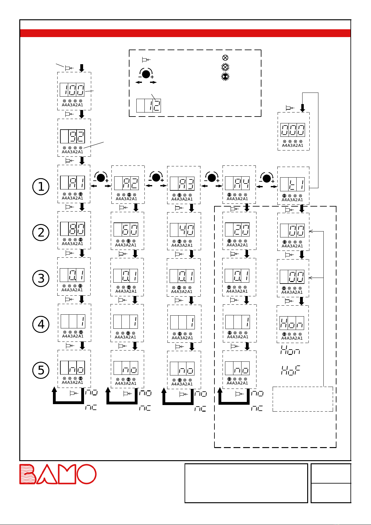
SETTING THE LIMIT SWITCHING POINTS A1...A4
1) Press the rotary/push switch 1x until A1 is displayed (LED A1 is blinking)!
2) Press the rotary/push switch again!
3) Set limit switching point 1 with rotary/pressure switch (2...100%, factory setting = 80%)!
4.) Press the rotary/push switch again!
5) Set the delay time!
6) Press the rotary/push switch again!
7) Set hysteresis!
8) Press the rotary/push switch again!
9.) Set normally closed/ normally open contact!
10) Press the rotary/push switch again!
Back to menu level 1
All other values can be selected and set in the same way (see figure "SETTING MENU").
The limit value switching points A1...A4 and the clock pulse generator are selected in menu level 1 (press the rotary/push switch 1x and select
with right/left).
If no setting is made for longer than approx. 10 seconds, the display jumps back to the current level and the setting values are permanently
saved.
SETTING THE CLOCK GENERATOR
Relay A4 can alternatively be used as a clock generator - however, this renders the setting values of the limit relay A4 ineffective!
Pump time (ON time):
Set the time so that, depending on the length of the measuring tube and the supply hose, air bubbles escape from the bottom of the measuring
tube for approx. 3...5 seconds during each pumping process!
Pause time (OFF time):
For liquids that can clog the measuring tube due to deposits, pumping should be carried out as required.
If the temperature of the liquid fluctuates, more frequent pumping will reduce the drift of the measured value.
In most cases, it is sufficient to pump for approx. 30 seconds once or twice a day.
SETTING THE CLOCK GENERATOR (continuation)
The clock is switched on as soon as the ON and OFF time is set greater than 0.
LEV
05-09-2023 M-592.03-EN-AB 592-03/4
HYDROSTATIC MULTIPLE
LIMIT VALUE SWITCH
MEMPRO S6.6
22, Rue de la Voie des Bans · Z.I. de la gare · 95100 ARGENTEUIL
Tel
Fax
+33 (0)1 30 25 83 20
+33 (0)1 34 10 16 05
Web
E-mail
www.bamo.eu
INTERNATIONAL

Adjustable parameters
ON-Time
As long as the set ON time is running, the contact of output relay 4 is closed.
Setting range: 1 second to 24 hours (factory setting: 0)
Available setting values:
0, 1, 2, 5, 10, 30 seconds: No decimal point lights up.
1, 2, 5, 10, 30 minutes: The right decimal point lights up.
1, 2, 3, 6, 12, 24 hours: The middle decimal point lights up
OFF-Time
As long as the set OFF time is running, the contact of output relay 4 is open.
Setting values as for "ON-Time", factory setting: 0
Note:
After a power failure (unit reboots), the programme starts with the ON time.
If one of the times is adjusted during operation, this setting is effective immediately.
Hold function
When using the clock for ventilation control, it is advisable to use the hold function.
The hold function can be activated in the timer menu.
This makes it possible to hold the last measured value during the aeration process (relay 4 energised) until the aeration is finished.
Available setting values:
HoF: Hold function switched off (factory setting)
Hon: Hold function switched on
The hold function has no effect if one of the timer times is set to 0.
CALIBRATION OF THE ZERO POINT
1.) Remove MEMPRO S6.6 / MEMPRO C S6.6 or empty tank completely!
2) In menu "t1", press the rotary/push switch for approx. 3 seconds until the LED display "circles".
The current fill level is set to 0 and permanently saved.
MAINTENANCE
When used as intended, the MEMPRO S6.6 / MEMPRO C S6.6 operates maintenance-free.
In case of strongly adhering liquids (e.g. milk of lime), the measuring tube or the measuring hose should be checked and cleaned at regular
intervals!
RESET TO FACTORY SETTING
1.) Switch on the power supply!
2) Within 3 seconds (during the test routine) hold down the rotary/push switch for approx. 5 seconds!
The display counts up 1, 2, 3, 4...99, hrs.
All setting values are reset to the factory setting (default values).
LEV
05-09-2023 M-592.03-EN-AB 592-03/5
HYDROSTATIC MULTIPLE
LIMIT VALUE SWITCH
MEMPRO S6.6
22, Rue de la Voie des Bans · Z.I. de la gare · 95100 ARGENTEUIL
Tel
Fax
+33 (0)1 30 25 83 20
+33 (0)1 34 10 16 05
Web
E-mail
www.bamo.eu
INTERNATIONAL

SETTING MENU
Press for 3
seconds
Basic setting 100% fill level
100% fill level
Display of current fill
level in %.
Relay 1 selection
Limit value
Delay time (seconds)
Hysteresis (%)
NC/NO contact
back to
Level 1
Relay 1
NO contact
NC contact
Press switch
Turn switch
Adjust value in submenus
LED off
LED on
LED blinking
Legend
Display blinking
LEDs light up when limit relay A1...A4
is energised
Limit value
Relay 2 selection
Delay time (seconds)
Hysteresis (%)
NC/NO contact
back to
Level 1
NO contact
NC contact
Relay 2
Relay 3 selection Relay 4 selection Clock selection
Limit value Limit value OFF-Time
Delay time (seconds) Delay time (seconds) ON-Time
Hysteresis (%) Hysteresis (%) Measurement
Hold Function
NC/NO contact NC/NO contact
back to
Hold function ON
Hold function OFF
Level 1
NO contact
NC contact
NO contact
back to
NC contact
Relay 3
Level 1
Relay 4 or clock
generator
Time domain
Sec. = no decimal point
Min. = right decimal point only
Hour = left decimal point only
Reset to factory setting
Press and hold
for 3 seconds
Zero point " circles"
LEV
05-09-2023 M-592.03-EN-AB 592-03/6
HYDROSTATIC MULTIPLE
LIMIT VALUE SWITCH
MEMPRO S6.6
22, Rue de la Voie des Bans · Z.I. de la gare · 95100 ARGENTEUIL
Tel
Fax
+33 (0)1 30 25 83 20
+33 (0)1 34 10 16 05
Web
E-mail
www.bamo.eu
INTERNATIONAL
This manual suits for next models
1
Table of contents
Other Bamo Switch manuals