B&H UTP Cable VBDP24AC-4-120 User manual

A-24-C/ A-25HD-4-120 / A-26HD-8-120 / A-27HD-16-120
UTP = Unshielded Twisted Pair 1R201302-V21
No need to worry
about power drop
for long cable run!
USER MANUAL
1
2
3
4
5
Video, Audio, Power and Data Transceiver Device – Camera Side
Model: VBDP-C
4-CH / 8-CH / 16-CH Video, Audio, Power, Data Transceiver Hub
Model:
The 4 / 8 / 16 channel transceiver hubs allow transmission of CCTV video, audio, AC power, and data over single network cable at the same time.
These devices use single CAT5 / 5e / 6 UTP cable as transmission medium and work together with the camera side transceiver device, VBDP-C. The
transceiver hub devices are capable of transmitting 4x / 8x / 16x channels of PAL, NTSC, SECAM color or monochrome video signals, mono monitor
audio, RS-485 or RS-232 signals up to 300m / 1000ft, and provide 12V DC or 24V AC power to each camera.
Transceiver Features – Camera Side:
• Receives video, audio, 24V AC/12V DC power, and data with one UTP cable
• Providing 24V AC or 12V DC for camera
• Up to 100m / 300ft (24V AC output); up to 300m / 1000ft (12V DC output)
• Strong Lighting Protection, ESDAnd anti-interference ability
• Delicate design, Support MIT frame, and easy installation
• RJ45 standard connection installation
Transceiver Hub Features – DVR Side:
• Using 150W / 300W / 600W AC Power, each Channel are independently chosen with output power 24V / 28V AC
• Transmit 4x / 8x / 16x channels video, audio, 24V / 28V AC power, and data over one UTP cable
• Anti-interference, Surge Protection, Anti-static Protection, Transient Shock Protection
• Hard Anti-rust Iron Shell
Part Name
Description
1 Audio Port Audio Signal Input
2 Video Port Video Signal Input
3 Data Port RS-485 Signal Input (Left is A / Right is B)
4 DC Power Port DC 12V Power Output (Left is + / Right is -)
5 AC Power Port AV/DC Power Output (Left is + / Right is -)
6 RJ45 Port
Standard RJ45 Plug. Check “Plug Production”
Green LED: Power; ON = normal; OFF = fail
Orange LED: Overload Protection Indicator
16 Channel
VBDP24AC-16-120 120V AC
8 Channel
VBDP24AC-8-120 120V AC
4 Channel
VBDP24AC-4-120 120V AC
VBDP24AC-4-120
VBDP-C
A-24-C
A-25HD-4-120
Front
Rear
Front
Front
Rear
Rear
VBDP24AC-8-120
VBDP24AC-16-120
A-26HD-8-120
A-27HD-16-120
6
A-24-C/ A-25HD-4-120 / A-26HD-8-120 / A-27HD-16-120
UTP = Unshielded Twisted Pair 2R201302-V21
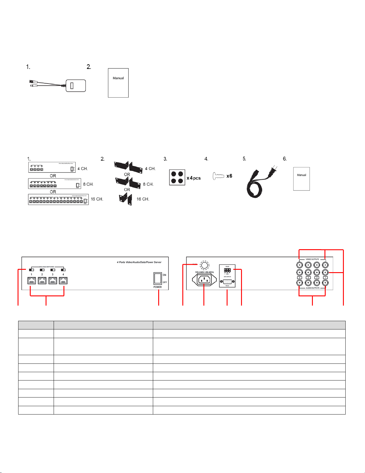
Package Contents:
Please check the device and accessories before installation. If any parts are missing, please contact your supplier.
VBDP-C:
1. One (1) Video, Audio, Power and Data Transceiver – Camera Side
2. One (1) User Manual
VBDP24AC-4-120 / VBDP24AC-8-120 / VBDP24AC-16-120:
1. One (1) VBDP24AC-4-120 or VBDP24AC-8-120 or VBDP24AC-16-120 Transceiver Hub
2. Two (2) Mounting Brackets for VBDP24AC-4-120 or VBDP24AC-8-120 or VBDP24AC-16-120
3. Four (4) Rubber Feet
4. Eight (8) Mounting Screws
5. One (1) Power Cord
6. One (1) User Manual
Transceiver Hub Panel Diagram:
Note: Image shown is for 4-CH Transceiver Hub
Front Rear
Part Name Description
1 DIP Switch Used to switch output power (Left is 24VAC / Right is 28V AC)
2 RJ45 Plug
Standard RJ45 Plug. Refer To “How to Make RJ45”
Green LED: Power Indicator
Orange LED: Over Current Protection Indicator
3 Power Switch To turn power ON / OFF
4 Fuse Wire 220V, 3A – Replaceable Fuse Wire
5 Power Port 220V AC Power Input (110V AC need to be customized)
6 RS-232 Connector RS-232 Control Signal Input
7 RS-485 Connector RS-485 Control Signal Input
8 Audio Connectors Audio Signal Output (x4 / x8 / x16 depending on model)
9 Video Connectors Dual Video Signal Output (x4 / x8 / x16 depending on model)
1 2 3
4 5 6 7 8 9

A-24-C/ A-25HD-4-120 / A-26HD-8-120 / A-27HD-16-120
UTP = Unshielded Twisted Pair 3R201302-V21
Application Diagram:
Installation:
Before installing, make sure all power is turned off. Installing these devices with electricity still on may damage it.
1. Connect the Camera Side Transceiver Device to the corresponding ports on the camera (BNC video, audio, power and data ports)
2. Connect a UTP cable to the RJ45 port of the Camera Side Transceiver Device.
3. Connect the other side of the UTP cable to the RJ45 port on the 4 / 8 / 16 Channel Transceiver Hub.
4. Use coaxial cable with BNC to connect one end from input terminal to BNC port of the receiving product output terminal.
5. Connect audio BNC port of Transceiver Hub to Audio Device (such as speakers) or to DVR.
6. Connect RS-232 or RS-485 port of Transceiver Hub to Keyboard or DVR devices to control cameras remotely.
7. Check whether installation is correct and all connections are securely connected.
8. Turn on power switch and check to see if all devices are functioning correctly as well as the image quality.
Specification for Transceiver Device – Camera Side: *Specifications are subject to change without notice
Model VBDP-C
Function Transmission Channel 1 (Video, Audio, 24V AC / 12V DC Power, and Data)
Distance Up to 100m / 300ft (24V AC output) ; up to 300m / 1000ft (12V DC output)
Power
Power Output to Camera 24V AC or 12V DC
Total Power 28V AC, 1A / 36V DC, 1A
Stable Power’s Max 12V DC, 1A
Stable Power’s Ripple Wave <100 mV
Video Transmission and
Property
Connector Screw Fix Port
Compatible System PAL / NTSC / SECAM video with RJ45 Port
Signal Transmission Width 0 ~ 6 MHz
Anti-interference >60 dB
Video Balun Port RJ45 Port
Audio Transmission and
Property
Connection Screw Fix Port
Bandwidth 20 ~ 20 kHz
Isolated Compression >500V
Control Signal Transmission
and Property
Port Screw Fix Port
Signal Category RS-485
Transmission Rate <500 Kbps
Protection ESD
1a Contact Discharge level 3
1b Air Discharge level 3
Per: IEC61000-4-2
Environment
Working Temperature 0°C ~ 50°C / 32°F ~ 122°F
Storage Temperature -20°C ~ 70°C / -4°F ~ 158°F
Humidity (non-condensation) 0 ~ 90%
Physical Properties
Size 81.5mm x 60mm x 25mm / 3.21” x 2.36” x 0.98”
Shell Aluminum
Color Black
Weight 145g / 5.11 oz
Stability MTBF >20000hrs

A-24-C/ A-25HD-4-120 / A-26HD-8-120 / A-27HD-16-120
UTP = Unshielded Twisted Pair 4R201302-V21
Specifications for Transceiver Hub – DVR Side: *Specifications are subject to change without notice
Model VBDP24AC-4-120 VBDP24AC-8-120 VBDP24AC-16-120
Function Channels QTY 4 Channel 8 Channel 16 Channel
Distance Up to 100m / 300ft (24VAC output) ; Up to 300m / 1000ft (12V DC output)
Power
Power Input 120V AC 120V AC 120V AC
Max Power
Consumption
150W 300W 600W
Output Power
Type
24V / 28V AC
Max
Transmission
Consumption
28V AC / 1A
Video
Transmission
and Property
Connector Female BNC Port (Dual Output)
Compatible
System
PAL, NTSC, SECAM
Signal
Transmission
Width
6 MHz
Anti-interference >60 dB
Video Balun
Port
RF45
Audio
Transmission
and Property
Connection Female BNC Port
Bandwidth 20 ~ 20 kHz
Isolation
Compression
>500V
Data Signal
Transmission
and Property
Port DB9 / Screw Fix Port
Signal Type RS-232 / RS-485
Transmission
Rate
<500 Kbps
Electromagnetic
Environment
Compatibility
Connector
Protection
2KV Per: IEC61000-4-5
ESD
1a Contact Discharge level 3
1b Air Discharge level 3
Per: IEC61000-4-2
Operation
Environment
Operation
Temperature
0°C ~ 50°C / 32°F ~ 122°F
Storage
Temperature
-20°C ~ 70°C / -4°F ~ 158°F
Humidity 0 ~ 95% (non-condensation)
Physical
Properties
Dimension
(L*W*H)
300mm x 300mm x 66.8mm /
11.81" x 11.81" x 2.63"
430mm x 300mm x 66.8mm / 16.93" x 11.81" x 2.63"
Shell Iron
Color Black
Weight 5.2 KG / 11.46 lbs 6.1 KG / 13.45 lbs 9.37 KG / 20.66 lbs
MTBF MTBF >20,000 hours
NOTE: The current supplied to the camera depends on the lengths & quality of the cable.
Troubleshoot:
Products are fully tested. If there are any failures, the problem(s) may be related to the following:
1. Please check if the product was damaged when it arrived. Was there any debris blocking the RJ45 port? Was it damaged when the customer
first received the product?
2. Please check if the BNC jumper and RJ45 connectors are good and reliable. Users should pay attention to details. Usually, some errors are
very low-level, but we need to fully evaluate the situation then can find the reasons.
To determine the status of the products, methods are:
1. See if the power lights are on. If so, the power supply has no problem. If they are not on, then the connection may be unstable. Check
whether any impurities in the RJ45 jack connector. If the LED lights are on, but the camera is not, please check if the connectors are reliable
and the wiring heads are correct.
2. The reliability of the BNC connector may also affect the video transmission.
Please gather all failed products and send it to us as soon as possible so that we can test and identify the problem. Please also collect the details of the
product’s applications to see if other problems are also caused by product failure! In addition, our quality control department will also check this product
immediately to see if there are other quality problems.

A-24-C/ A-25HD-4-120 / A-26HD-8-120 / A-27HD-16-120
UTP = Unshielded Twisted Pair 5R201302-V21
Troubleshooting For Transceiver Hub
If the device trouble happened, please refer to the following solutions:
•Make sure whether device installation is according to installation manual.
•If choose RJ-45, make sure both ends of UTP cable are the same (both 568A or both 568B).
•Max transmission distance is depends on electric environment, do not exceed it.
•Please check whether connection where connected correctly to the device.
•Please contact your supplier if trouble still exists.
How to Make RJ45 Jacks:
Instruments to be used: wire crimper, network tester. Wire sequence of RJ45 plug should conform with EIA/TIA568A or 568B.
1. Shuck off about 2cm of the insulating layer, and bar the 4 pairs UTP cable
2. Depart the 4 pairs UTP cable and straighten them.
3. Line up the 8 pieces of cables per EIA/TIA 568A or 568B.
4. Brunt cut the cables to leave 1.5cm bare wire.
5. Plug 8 cables into RJ45 plug; make sure each cable is in each pin.
6. Then use wire crimper to crimp it.
7. Repeat above 5 steps on the other end.
8. Using network tester to detect the cable whether it works normally.
Limited Warranty:
Caution :
•Do not handle the unit with wet hands.
•The unit is not waterproof and should not be used outdoors.
TIA568A T568 Character
1 White/Green Stripe White/Orange Stripe Video +
2 Green Solid Orange Solid Video -
3 White/Orange Stripe White/Green Stripe Data +
4 Blue Solid Blue Solid Power -
5 White/Blue Stripe White/Blue Stripe Power -
6 Orange Solid Green Solid Data -
7 White/Brown Stripe White/Brown Stripe
Power + &
Audio +
8 Brown Solid Brown Solid
Power + &
Audio -
1 2 3 4 5 6 7 8
LIMITED ONE (1) YEAR WARRANTY AND EXCLUSIONS
Manufacturer warrants to the original consumer purchaser and not for the benefit of anyone else that this product at the time of its sale by
Manufacturer is free of defects in materials and workmanship under normal and proper use for one (1) year from the purchase date. Manufacturer's
only obligation is to correct such defects by repair or replacement, at its option, if within such one (1) year period the product is returned prepaid, with
proof of purchase date, and a description of the problem. This warrant excludes and there is disclaimed liability for labor for removal of this product
or reinstallation. This warranty is voided if this product is installed improperly or in an improper environment, overloaded, misused,
opened, abused, or altered in any manner, or is not used under normal operating conditions or not in accordance with any labels or
instructions. There are no other implied warranties of any kind, including merchantability and fitness or a particular purpose, but if any
implied warranty is required by the applicable jurisdiction, the duration of any such implied warrant, including merchantability and fitness of or a
particular purpose, is limited to one (1) year. Manufacturer is not liable for incidental, indirect, special, or consequential damages, including
without limitation, damage to, or loss of use of, any equipment, loss sales or profits or delay or failure to perform this warranty obligation.
The remedies, provided therein are the exclusive remedies under this warranty, whether based on contract, tort or otherwise.

A-24-C/ A-25HD-4-120 / A-26HD-8-120 / A-27HD-16-120
UTP = Unshielded Twisted Pair 6R201302-V21
CAUTION!!!
Failure to read this notice may result in damaging
the camera or device in which the warranty will be voided
due to installation error.
When using any type of RJ45 jack powered balun, a Cable Tester must be used to ensure proper
connection. Many individuals can make RJ45 connections easily, however mistakes can be made. When
making connections for powered baluns, make sure to test the connectivity and ensure proper alignment
on both sides.
When using passive or active baluns, the alignment of the cable is imperative to the success of the operation. Use a Cable Tester
because it is a very simple, yet easy to find tool that can save a huge headache. For example, if one of the video wires accidentally
gets crimped into the power side, and the powered balun is then hooked up to the camera, both the camera and the balun have just
burned out. This is an extremely costly mistake, not only in dollars but time as well. How long does it take to test the RJ45 using a
Cable Tester? Less than one minute.
The new terms and conditions state: When an RMA is requested and the product has been burned by bad RJ45 connections,
the product is NO LONGER covered under warranty.
Note: Whichever way the RJ45 is terminated on one end of the cable, IT MUST BE THE SAME ON THE OTHER SIDE for either
TIA/EIA 568Aor TIA/EIA 568B. Below is an example of TIAEIA 568B.
Cable Tester
1 2 3 4 5 6 7 8
1 2 3 4 5 6
Pair 3
Pair 1
Pair 2
Pair 4
TIA/EIA 568B
Pin
Pair
Color
Character
1
2
Orange / White
Video +
2
2
Orange
Video –
3
3
Green / White
Power –
4
1
Blue
Power –
5
1
Blue / White
Power –
6
3
Green
Power +
7
4
Brown / White
Power +
8
4
Brown
Power +
This manual suits for next models
2
Popular Switch manuals by other brands


D-Link
D-Link DGS-1008P Quick installation guide

BERNSTEIN
BERNSTEIN CSMS-M-RRS-H-KA Installation and operating instructions

Veris Industries
Veris Industries H909 installation guide

ICP DAS USA
ICP DAS USA I-7514U quick start guide

SAINT-GOBAIN
SAINT-GOBAIN PRIVA-LITE installation guide

Lindy
Lindy 38032 user manual