B&K VMR6 User manual

CONTENTS
PAGE
i
i
B
&
K
"Repeatability"
1
The
VMR-6.5.4
-
Its
Purpose
and
Function
2
Design
and
Construction
2
i
!
Setting
up
the
VMR-6.5.4
2
Safety
&
Care
Considerations
3
The
Inputs
and
Outputs
3
System
Installation
4
Making
the
Connection
4
Setup
and
Checkout
5
Alternate
System
Configurations
5
In
Case
of
Difficulty
6
Fig..
2
-
Rear
Panel
Diagram
7
Fig.
3
-
Speaker
Wiring
Diagram
8
Fig.
4
-
Layout
Diagram
8
Specifications
8
|
Warranty
Inside
Back
Cover
[FC

"Repeatability"
-
your
assurance
of
a
product
reliability
In
days
gone
by,
the
term
"created
carefully
by
skilled
craftsmen”
exemplified
the
meaning
behind
'quality
assurance',
In
the
modern
manufacturing
environment,
those
same
skilled
craftsmen
now
design
the
processes
that
allow
the
economies
of
volume
manufacturing,
while
still
retaining
the
same
high
standards
of
quality.
"Repeatability",
is
the
B
&
K
house
term
for
a
quality
assurance
philosophy
that
is
the
culmination
of
several
well
engineered
manufacturing
processes.
The
four
most
important
of
these
are;
(a.)
a
manufacturing
process
that
functions
in
exactly
the
same
manner
with
each
and
every
audio
component;
(b.)
a
comprehensive
test
of
each
and
every
component
part
prior
to
installation
in
the
circuit
board;
(c.)
final
assembly
by
an
experienced
assembler,
and
(d.)
a
comprehensive,
functional
test
prior
to
final
packaging.
As
a
first
step
towards
manufacturing
a
’repeatable'
component,
B
&
K
employs
the
use
of
the
latest
technology
in
automatic
insertion
equipment
at
their
manufacturing
facility
in
Buffalo,
New
York.
Not
only
does
this
process
provide
a
complete
and
exact
duplication
of
each
and
every
circuit
board,
it
imposes
a
full
test
of
each
individual
component
just
prior
to
insertion
in
the
circuit
board.
Should
any
component
fail,
the
process
is
halted
automalically.
It
can
only
be
resumed
when
the
faulty
component
is
replaced
with
a
serviceable
unit
which,
itself,
must
undergo
the
same
testing
procedure
before
the
process
can
resume.
All
assembly
is
done
by
technicians
who
are
trained
in
the
art
of
doing
the
job
right
the
first
time.
Following
assembly,
the
unit
is
tested
rigorously
for
specification
and
reliability.
Only
then
is
the
unit
packaged
for
shipment.
Our
Pledge
to
You
The
decision
to
purchase
an
audio
component
is
one
you
have
not
taken
lightly.
We
expect
you
will
be
seeking
affirmation
that
your
choice
of
a
B
&
K
audio
product
was
wise
and
practical
and
that
it
continues
to
meet
your
sonic
expectations
each
time
you
turn
it
on.
The
keystone
of
B
&
K
Components
Ltd.
success
is
based
on
taking
the
quality
and
consistency
of
our
products
and
the
needs
of
our
customers
very
seriously.
Therefore,
when
you
make
an
investment
in
a
B
&
K
audio
product,
we
feet
sure
your
satisfaction
with
its
musical
consistency
and
solid
operational
reliability
will
increase
with
each
passing
day.
Also,
should
you
ever
have
a
question
about,
or
a
problem
with,
any
B
&
K
product,
we
are
but
a
phone
or
FAX
call
away.
Thank
you
for
choosing
a
B
&
K
audio
product.
You
will
not
be
disappointed.
Happy
listening,
B
&
K
Components
Ltd.
Buffalo,
New
York

THE
VMR-
6.5.4
-
ITS
PURPOSE
AND
FUNCTION
An
exciting
and
reliable
source
of
high
fidelity,
audio
signal
amplification,
the
VMR-6.5.4
offers
excellent
versatility
and
cost
effectiveness
for
most
multi-channel,
home
entertainment
systems.
The
VMR-6.5.4
is
primarily
a
6
channel
amplifier
capable
of
delivering
a
clean,
fully
musical,
60
watts
r.m.s.
power
output
per
channel(8
ohm
load).
As
well,
the
VMR-6.5.4
offers
a
'bridging
feature
which
allows
those
6
channels
to
be
combined
into
three
more
powerful
Channels.This
presents
an
opportunity
to
use
the
VMR-6.5.4
in
a
number
of
configurations
for
a
variety
of
uses;
the
standard
6
channel
mode;
or
a
5
,
4
or
3
channel
mode.
Such
versatility
makes
the
VMR-6.5.4
a
particularly
compact
source
for
a
multiplicity
of
surround
-sound
or
multi-room
applications.
While
the
B
&
K
Components
Ltd.
VMR-6.5.4
is
engineered
to
interact
harmoniously
with
all
popular
sources
and
line
stages,
the
match
that
approaches
perfection
is
that
of
being
driven
by
any
one
of
the
excellent
B
&
K
preamplifiers
presently
available.
DESIGN
AND
CONSTRUCTION
The
VMR-6.5.4
utilizes
high
quality
electronic
circuitry
to
achieve
an
environment
wherein
a
detailed,
transparent
and
highly
musical
sound
can
be
realized.
The
high
quality
parts
compliment
includes
state-of-the-art
solid
state
devices;1%
metal
film
resistors;
computer
grade
electrolytic
power
supply
capacitors
and
a
high
capacity
toroid
transformer.
The
VMR-6,5,4
operates
class
AB
employing
very
high
current
MOSFET
power
output
stages.
As
such
it
is
capable
of
reproducing
the
most
demanding
digital
or
analog
recordings
at
full
rated
power
levels.
SETTING
UP
THE
VMR-6.5.4
Placement
of
the
amplifier
is
important
and
requires
some
pre-planning.
In
order
to
eliminate
interference
being
induced
in
the
amplifier
by
other
components,
It
must
be
physically
located
a
safe
distance
away
from
all
source
components.
This
will
avoid
their
being
influenced
by
the
fields
being
propogated
by
the
amplifier
when
it
is
under
heavy
load.
Ideally
the
VMR-6.5.4
will
be
located
near
the
speakers.
This
will
minimize
the
adverse
effects
of
inductance,
capacitance
and
any
damping
effect
that
might
result
from
speaker
wires
interacting
with
the
amplifier.
The
VMR-6.5.4
is
equipped
with
raised
feet
so
that
continuous
ventilation
can
be
maintained.
As
well,
they
help
to
maintain
acoustic
feedback
into
the
amplifier
at
a
minimum.
They
also
provide
a
measure
of
protection
against
scratching
any
surface
the
unit
might
be
resting
on.
Note:
Acoustic
feedback
can
be
identified
as
tow
frequency
vibrations
which
are
not
part
of
the
signal
from
the
source
material.
They
also
have
a
tendency
to
become
louder
and
less
controllable
as
you
increase
the
system
volume.
The
most
common
source
of
acoustic
feedback
interference
is
the
result
oi
having
the
preamplifier
and
source
components
too
close
to
the
loudspeakers.
2
.

SAFETY
&
CARE
CONSIDERATIONS
CONNECTING
AND
DISCONNECTING
CABLES
In
order
to
eliminate
potential
damage
to
the
speakers
and
other
components
in
the
system,
always
turn
off
the
amplifier
before
unplugging
or
plugging
in
the
preamplifier's
power
cord.
This
caution
is
also
applied
to
plugging
in
or
unplugging
the
interconnect
cables
running
from
the
preamplifier
to
the
amplifier.
When
plugging
in
or
unplugging
interconnect
cables
running
from
source
to
preamplifier,
always
rotate
the
preamplifier's
volume
control
to
minumum
and
if
available
mute
the
preamplier
first.
POWER
LINE
MODULATION
INTERFERENCE
During
heavy
passages,
the
power
needs
of
the
amplifier
may
fluctuate
considerably.
As
these
needs
are
felt
at
the
power
source,
the
line
voltage
available
will
in
turn
fluctuate,
based
on
the
instantaneous
power
requirement
of
the
amplifier.
It
is
an
effect
somewhat
like
one
person
trying
to
hold
on
to
the
end
of
a
rope
while
another
person
at
the
other
end
is
jerking
it
at
random
intervals.
Therefore
we
recommend
that
you
-
AVOID
CONNECTING
THE
PREAMPLIFIER
OR
THE
SOURCE
COMPONENTS
TO
THE
SAME
POWER
SOURCE
AS
THE
AMPLIFIER
To
do
so
may
subject
the
preamplifier
and
its
sources
to
power
line
modulation
interference
which
could
affect
the
operation
of
the
component,
thereby
resulting
in
a
degraded
audio
signal
from
the
source.
THE
INPUTS
AND
OUTPUTS
Located
on
the
rear
panel,
they
are;
INPUTS
There
are
6
input
signal
connections
to
the
VMR-6.5.4
amplifier
through
high
quality,
gold-plated
connectors.
They
accommodate
audio
cables
utilizing
standard
RCA
plugs.
[See
Fig.
1(a)].
OUTPUTS
There
are
6,
high
quality,
5-way
binding
posts;
one
for
each
channel.
They
are
designed
to
accept
a
banana-type
plug
or
a
spade
lug
connector,
[see
Fig.
1(b)
&
(c)]
DO
NOT
REMOVE
CABINET
FEET,
KEEP
AMPLIFIER
WELL
VENTILATED
AT
ALL
TIMES.

SYSTEM
INSTALLATION
CONSIDERATIONS
There
will
most
likely
be
a
number
of
cables
involved
in
the
installation
of
your
home
entertainment
system.
Therefore,
pre-planning
is
essential
in
order
to
maximize
system
efficency.
We
recommend
the
following
as
a
means
of
helping
you
reach
that
goal.
-
Use
the
diagram
on
page
8
of
this
manual,
or
make
your
own
diagram
of
your
proposed
system,
to
lay
out
the
location
of
components,
the
VMR-6.5.4.
and
the
proposed
cable
runs
between
them
in
the
room.
Number
each
cable
and
record
its
length
on
the
drawing
for
future
reference.
For
example,
"
#
3
-
IN
-1
2
*
"
denotes
input
cable
from
source
channel
#
3
and
that
it
is
12
feet
long.
"
#
1
OUT
(L.REAR)
-
20"
denotes
that
#
3
speaker
output
has
been
assigned
to
the
left
rear
speaker
and
that
its
length
is
20
feet.
-
Cable
runs
are
critical
in
that
they
must
be
kept
away
from
sources
of
power
radiationfamplifiers,
power
cords,heaters
etc.).
For
the
sake
of
safety,
they
should
also
be
kept
out
of
traffic
areas.
-
The
process
of
optimizing
the
system
will
include
the
type
of
cable,
the
length
of
run
and
the
obstructions
it
must
deal
with
along
its
run.Your
dealer
can
advise
you
on
the
products
available
and
their
relative
merits.
If
building
custom-length
audio
cables
is
not
your
strength,
your
dealer
should
be
able
to
help
you
with
that
as
well.
If
you
would
like
to
utilize
the
bridging
option
which
converts
two
channels
in
order
to
create
a
more
powerful
single
channel,
see
the
ALTERNATE
SYSTEM
CONFIGURATIONS
section.
For
the
standard
configuration
of
one
channel
source
per
input,
most
of
the
planning
will
be
in
determining
which
input
you
wish
to
apply
to
which
channel.
A
typical
connection
diagram
is
shown
in
Fig.
3(a).
For
other
methods
of
setting
up
your
system,
see
the
section
ALTERNATE
SYSTEM
CONFIGURATIONS.
MAKING
THE
CONNECTION
1.
Before
doing
anything,
ensure
that
the
power
switch
on
the
amplifier's
front
panel
is
in
the
'off'
position.
Again,
it
is
recommended
that
you
locate
a
separate
AC
power
outlet
for
the
VMR-6.5.4,
one
that
is
not
shared
by
any
other
audio
component
in
the
system.
This
will
eliminate
the
possibility
of
the
amplifier
'modulating'
the
power
being
supplied
to
the
component
and
compromising
the
signal
originating
from
that
component.
2.
Locate
the
AC
power
supply
cord
and
plug
it
into
the
power
input
receptacle
in
the
rear
panel.
Do
not
connect
it
to
the
AC
power
supply
as
yet.
3.
Connect
the
audio
cables
from
your
preamplifier's
output
to
the
selected
channel's
input
connectors.
Make
note
of
the
input
number(as
suggested
in
the
"Considerations"
section
above)
so
that
the
correct
speaker
cable
can
be
connected
to
the
speaker
output
with
the
same
number,
A
rear
panel
connection
guide
is
shown
in
Fig.
2(a).
4.
C
onnect
the
cables
from
your
speakers
to
the
appropriate
CHANNEL
output.

MAKING
THE
CONNECTION
(conl’d
)
5.
Double-check
the
cable
connections(both
ends)
to
ensure
they
are
plugged
into
the
correct
jacks
for
the
source
(L
or
R
-
front,
rear
or
side)
and
that
the
connection
is
tight.
6.
With
the
volume(gain)
control
on
your
preamplifier
set
to
full
minimum,
or
switched
to
'mute',
plug
the
amplifier’s
power
cord
into
the
AC
power
source.
Turn
the
VMR-6.5.4
power
switch
'on
1
.
The
panel
light
above
the
switch
should
be
illuminated.
7.
Place
all
level
controls
on
the
VMR-6.5.4
at
maximum.
SETUP
AND
CHECKOUT
The
next
task
will
require
that
you
listen
to
a
source
sampling(tape,
CD
etc.),
noting
the
levels
al
each
point
within
the
system.
During
the
initial
listening
situation,
you
may
find
the
dispersion
of
sound
to
be
unbalanced.
This
could
be
the
result
of
where
you
are
in
relation
to
the
speakers.
It
could
also
be
the
room
acoustics;
or,
it
could
be
the
manner
in
which
the
signal
is
being
distributed
in
the
stages
prior
to
the
amplifier,
The
VRM-6.5.4
provides
you
with
levei
controls
for
each
channel
so
you
can
adjust
the
relative
volume
of
each
channel
to
suit
your
personal
taste.
While
initial
audio
quality
will
be
very
good,
it
should
get
even
better.
Most
high
performance,
audio
amplifiers
require
about
40
hours
of
circuit
forming
{'burn-in')
time
before
maximum
fidelity
wifi
be
fully
realized.
Helpful
Mini:
Some
audiophiles
prefer
to
inaugurate
the
system
as
a
unitfpreamplifier.
cables
and
amplifier).
If
this
is
your
preference,
you
might
try
playing
a
CD
into
the
system
for
about
24
hours
straightfspeakers
connected),
at
a
low
but
listenable
volume
level,
as
one
method
of
'forming'
the
components
and
signal
pathways.
Should
you
encounter
any
inconsistencies
that
cannot
be
traced
to
the
source
or
the
material
being
played,
consult
the
IN
CASE
OF
DIFFICULTY
in
this
manual.
ALTERNATE
SYSTEM
CONFIGURATIONS
CHANNEL
BRIDGING
Channels
1
&
2,
3
&
4
and
5
&
6
are
available
for
bridging
in
order
to
provide
3
channels
capable
of
providing
120
watts
r.m.s.
into
an
8
ohm
load.
However,
due
to
the
relative
complexity
of
the
modification
it
is
recommended
that
this
conversion
be
carried
out
by
your
dealer's
technician
or
at
the
B
&
K
factory
in
order
to
comply
with
warranty
requirements.
For
more
information
on
bridging
the
VMR-6.5.4,
please
contact
your
dealer
or
B
&
K
directly.
BI-WIRING
Bi-wiring
has
the
potential
of
doing
away
with
much
of
the
'mud'
associated
with
processing
all
incoming
frequencies
at
one
input
on
the
crossover
network.
As
a
result,
most
frequencies,
especially
the
bass
will
appear
tighter
and
more
resiliant.
The
mid
range
and
the
highs
will
be
clearer.
How
effectively
this
is
accomplished
will
vary
from
one
speaker
design
to
another.
5
.
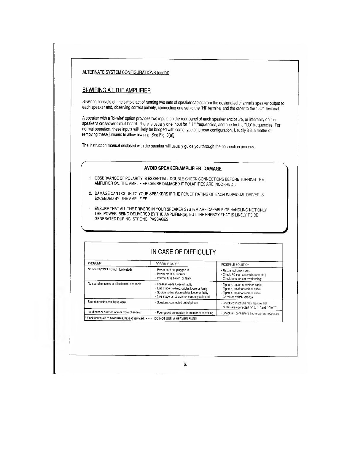
BI-WIRING
AT
THE
AMPLIFIER
'NS
(cffllttfl
Bi-wiring
consists
of
the
simple
act
of
running
two
sets
of
speaker
cables
from
the
designated
channel's
speaker
output
to
each
speaker
and,
observing
correct
polarity,
connecting
one
set
to
the
"HI"
terminal
and
the
other
to
the
"LO"
terminal.
A
speaker
with
a
’bi-wire’
option
provides
two
inputs
on
the
rear
panel
of
each
speaker
enclosure,
or
internally
on
the
speaker's
crossover
circuit
board.
There
is
usually
one
input
for
"HI”
frequencies,
and
one
for
the
"LO”
frequencies.
For
normal
operation,
these
inputs
will
likely
be
bridged
with
some
type
of
jumper
configuration.
Usually
it
is
a
matter
of
removing
these
jumpers
to
allow
biwiring.[See
Fig.
3(a)]
The
instruction
manual
enclosed,
with
the
speaker
will
usually
guide
you
through
the
connection
process,
AVOID
SPEAKER/AMPLIFIER
DAMAGE
^
1
OBSERVANCE
OF
POLARITY
IS
ESSENTIAL
DOUBLE-CHECK
CONNECTIONS
BEFORE
TURNING
THE
AMPLIFIER
ON.
THE
AMPLIFIER
CAN
BE
DAMAGED
IF
POLARITIES
ARE
INCORRECT.
2.
DAMAGE
CAN
OCCUR
TO
YOUR
SPEAKERS
IF
THE
POWER
RATING
OF
EACH
INDIVIDUAL
DRIVER
IS
EXCEEDED
BY
THE
AMPLIFIER
.
-
ENSURE
THAT
ALL
THE
DRIVERS
IN
YOUR
SPEAKER
SYSTEM
ARE
CAPABLE
OF
HANDLING
NOT
ONLY
THE
POWER
BEING
DELIVERED
BY
THE
AMPLIFIER(S),
BUT
THE
ENERGY
THAT
IS
LIKELY
TO
BE
GENERATED
DURING
STRONG
PASSAGES.
N---
J
IN
CASE
OF
DIFFICULTY
PROBLEM
POSSIBLE
CAUSE
POSSIBLE
SOLUTION
No
sound
('ON'
LED
not
illuminated)
-
Power
cord
not
plugged
in
-
Power
off
al
AC
source
-
Internal
fuse
blown
or
faulty
-
Reconnect
power
cord
-
Check
AC
sourcciswitch,
fuse
etc.)
-
Check
tor
shorts
or
overloading'
No
sound
on
some
or
all
selected
channels
-
speaker
leads
loose
or
faulty
-
Line
stage
-to-amp.
cables
loose
or
faulty
-
Source
to-iine
stage
cables
loose
or
faulty
-
Line
stage
or
source
not
correctly
selected
-
Tighten,
repair
or
replace
cable
-
Tighten,
repair
or
replace
cable
-
Tighten,
repair
or
replace
cable
-
Check
all
switch
settings
Sound
directionless,
bass
weak
-
Speakers
connected
out
of
phase
-
Check
connections
making
sure
that
cables
are
connected
"+"
to
and
to
Loud
hum
or
buzz
on
one
or
more
channels
-
Poorgound
connection
in
interconnect
cabling
■
Check
ah
connectors
and
repair
as
necessary
*
If
unit
continues
to
blow
fuses,
have
it
serviced.
—
DO
NOT
USE
A
HEAVIER
FUSE!
6
.


Fig.
3
The
two
configurations
shown
represent
the
most
common
forms
of
wiring
the
speaker.
Always
double-check
to
make
sure
polarity
is
correct.
VMR-65.4
(o)
STANDARD-WIRED
SPEAKER
CONFIGURATION
Fig.
4
A
diagram
showing
a
multichannel
layout
of
up
1o
6
channels
using
the
VMR-6.5.4
as
the
main
amplifier.
The
Blocks
adjaceni
to
each
speaker
location
can
be
used
to
enter
information
on
how
you
have
your
system
setup.
There
is
also
a
listing
point
for
source
outputs
in
the
event
you
are
driving
the
amplifier
from
something
olher
than
a
single,
mufti-charnel
(more
than
2
channel)
source.
SPECIFICATIONS
Power
Rating
-
8
ohms
60
watts
Frequency
Response
5Hz
-45KHz
Input
Sensitivity
900
millivolts
THD
(S+N)
0.09%
@
1
kHz
Input
Impedance
24,300
ohms
Damping
Factor
100@50Hz
Current
14
amps
(peak-peak)
Slew
Rate
14
volts/microsecond
!
Dynamic
Headroom
1.4dB
S/N
(A-weighted)
95dB
Voltage
Gain
j
24.3
Line
Power
120VAC
(Fuse:
12ASIo
Bio)
Dimensions
17"(w)
x
15.5"(d)
x
5.25”(h)
[O.A.]
Weight
35
lb.
(16.0Kg)
Specifications
Subject
To
Change
Without
Notice.
8
.
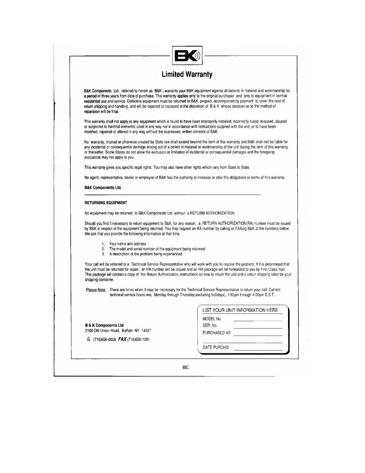
Limited
Warranty
B&K
Components
Ltd.,
referred
to
herein
as
B&K,
warrants
your
B&K
equipment
against
all
defects
in
material
and
workmanship
for
a
period
of
three
years
from
date
of
purchase.
This
warranty
applies
only
to
the
original
purchaser
and
only
to
equipment
in
normal
residential
use
and
service.
Defective
equipment
must
be
returned
to
B&K,
prepaid,
accompanied
by
payment
to
cover
the
cost
of
return
shipping
and
handling,
and
will
be
repaired
or
replaced
at
the
discretion
of
B
&
K
whose
decision
as
to
the
method
of
reparation
will
be
final.
This
warranty
shall
not
apply
to
any
equipment
which
is
found
to
have
been
improperly
installed,
incorrectly
fused;
misused,
abused
or
subjected
to
harmful
elements;
used
in
any
way
not
in
accordance
with
instructions
supplied
with
the
unit;
or
to
have
been
modified,
repaired
or
altered
in
any
way
without
the
expressed,
written
consent
of
B&K.
No
warranty,
implied
or
otherwise
created
by
Stale
law
shall
extend
beyond
the
term
of
this
warranty
and
B&K
shall
not
be
liable
for
any
incidental
or
consequential
damage
arising
out
of
a
defect
in
material
or
workmanship
of
the
unit
during
the
term
of
this
warranty
or
thereafter.
Some
States
do
not
allow
the
exclusion
or
limitation
of
incidental
or
consequential
damages
and
the
foregoing
exclusions
may
not
apply
to
you.
This
warranty
gives
you
specific
legal
rights.
You
may
also
have
other
rights
which
vary
from
State
to
Stale.
No
agent,
representative,
dealer
or
employee
of
B&K
has
the
authority
to
increase
or
alter
the
obligations
or
terms
of
this
warranty.
B&K
Components
Ltd.
RETURNING
EQUIPMENT
No
equipment
may
be
returned
to
B&K
Components
Ltd.
without
a
RETURN
AUTHORIZATION.
Should
you
find
it
necessary
to
return
equipment
to
B&K,
for
any
reason,
a
RETURN
AUTHORIZATION(RA)
number
must
be
issued
by
B&K
in
respect
of
the
equipment
being
returned.
You
may
request
an
RA
number
by
calling
or
FAXing
B&K
at
the
numbers
below.
We
ask
that
you
provide
the
following
information
at
that
time.
1.
Your
name
and
address
2.
The
model
and
serial
number
of
the
equipment
being
returned.
3.
A
description
of
the
problem
being
experienced.
Your
call
will
be
referred
to
a
Technical
Service
Representative
who
will
work
with
you
to
resolve
the
problem.
If
it
is
determined
that
the
unit
must
be
returned
for
repair,
an
RA
number
will
be
issued
and
an
RA
package
will
be
forwarded
to
you
by
First
Class
mail.
This
package
will
contain
a
copy
of
the
Return
Authorization;
instructions
on
how
to
return
the
unit
and
a
return
shipping
label
for
your
shipping
container.
Please
Note:
There
are
times
when
It
may
be
necessary
for
the
Technical
Service
Representative
to
return
your
call.
Current
technical
service
hours
are;
Monday
through
Thursday(excluding
holidays),
1:00pm
through
4:00pm
E.S.T..
B&K
Components
Ltd.
2100
Okl
Union
Road,
Buffalo
NY
14227
&
(716)656-0026
FAX
(716)656-1291
^
LIST
YOUR
UNIT
INFORMATION
HERE
MODEL
No.
_
SER.
No.
_
PURCHASED
AT:
[DATEPURCfTD
IBC

(£)
Copyright
1992
B
&
K
Components
Ltd.
2100
Old
Union
Road,
Buffalo
NY
14227
Tel
(716)656-0026
FAX
(
716)656-1291
This manual suits for next models
2
Table of contents
Other B&K Amplifier manuals


