B&K HD6 User manual

B&K Components, Ltd.
HD6
6 Zone
Transcoding
High Definition
Video Switcher
User Manual
SBIMPLY ETTER!
BK&
13840 040106

ii
USER MANUAL - HD6
© 2006 B&K Components, Ltd. All rights reserved.
The information in this manual is copyright protected. No part of this manual may be copied or reproduced in any form without prior
written consent from B&K Components, Ltd.
B&K Components Ltd. SHALL NOT BE LIABLE FOR OPERATIONAL, TECHNICAL OR EDITORIAL ERRORS/OMISSIONS MADE IN
THIS MANUAL. The information in this manual is subject to change without prior notice.
Product Information Acessories Included
Limited Warranty
B&K Components, Ltd., referred to herein as B&K, warrants your B&K equipment against all defects in material and workmanship for a period of five
years from the date of purchase. This warranty applies only to the original purchaser and only to equipment in normal residential use and service.
Defective equipment must be returned to B&K, prepaid, accompanied by proof of purchase and sufficient payment to cover the cost of return shipping
and handling, and will be repaired or replaced at the discretion of B&K whose decision as to the method of reparation will be final.
This warranty shall not apply to any equipment which is found to have been improperly installed, incorrectly fused, misused, abused, or subjected to
harmful elements, used in any way not in accordance with instructions supplied with the unit, or to have been modified, repaired or altered in any way
without the expressed, written consent of B&K. This warranty does not apply to the cabinet or appearance items such as the faceplate or control buttons,
nor does it cover any expenses incurred in shipping the unit to and from the manufacturer's service department.
This warranty on B& K Components, Ltd. products is NOT VALID if the products have been purchased from an unauthorized dealer or an E-tailer or if the
original factory serial number has been removed, defaced or replaced in any way. B& K Components, Ltd. sells its products through authorized dealers
in order to ensure that consumers obtain proper dealer service and support. Buying from an authorized B&K Components, Ltd. dealer insures that you
have a FACTORY WARRANTY on your B&K Components, Ltd. product. If you have any questions concerning your Factory Warranty call
B& K Components, Ltd. at 716-656-0026.
Upgradeability : B& K is one of the first manufacturers in the audio/video industry to consistently offer software and hardware upgrades to its processing
of audio signals. Through upgrades B&K delivers exceptional value to its customers. But what is "upgradeability"? Upgradeability is not a guarantee; we
define it as a philosophy of designing and manufacturing products so that as audio technology evolves, B&K can provide enhancements and improve-
ments to its products that are economically viable.
THE EXPRESS FACTORY WARRANTY HEREIN CONTAINED IS IN LIEU OF ANY AND ALL OTHER WARRANTIES, EXPRESSED OR IMPLIED,
INCLUDING ANY WARRANTY OF MERCHANTABILITY, UPGRADEABILITY OR OF FITNESS FOR ANY PARTICULAR PURPOSE. B &K COMPO-
NENTS, LTD. SHALL NOT UNDER ANY CIRCUMSTANCES BE LIABLE FOR DAMAGES, INCLUDING SPECIAL, INCIDENTAL, EXEMPLARY,
PUNITIVE OR CONSEQUENTIAL DAMAGES ARISING OUT OF OR IN CONNECTION WITH THE PURCHASE, USE OR PERFORMANCE OF ANY
B& K PRODUCT.
This warranty gives you specific legal rights. You may also have other rights which vary from State to State. Some States do not allow the exclusion or
limitation of incidental or consequential damages and the foregoing exclusions may not apply to you.
No agent, representative, dealer or employee of B & K has the authority to increase or alter the obligations or terms of this warranty.
Returning Equipment
No equipment may be returned to B& K Components, Ltd. without a RETURN AUTHORIZATION (RA). Should you find it necessary to return equipment
to B&K, for any reason, a RETURN AUTHORIZATION (RA) number must be issued by B& K in respect to the equipment being returned. You may request
an RA number by calling B & K at the numbers below. We will need the following information to issue your RA number. Please have it ready before you
call.
1. Your name, address, and phone number.
2. The model and serial number of the equipment being returned.
3. A description of the problem being experienced.
4. Your sales receipt.
Your call will be referred to a Technical Service Representative who will work with you to resolve the problem. If it is determined that the unit must be
returned for repair, an RA number will be issued.
SIMPLY BETTER! is a registered trademark of B & K Components, Ltd.
Limited Warranty
1 - HD6 User Manual
1 - Power Cord
1 - MZ128 Remote Control
1 - BKcSuite Setup CDROM
1 - DB-9 to RJ-45 Adapter
2 - S-Video to RCA Adapters
BK&
SBIMPLY ETTER!
2100 Old Union Road Buffalo, NY 14227 1-800-543-5252 In NY: 716-656-0026 fax: 716-656-1291
Date of Purchase: _______________________
Product Model #: _______HD6____________
Serial Number:__________________________
Purchased From: _______________________
Address: ______________________________
Phone #: ______________________________

1
Table of Contents
SBIMPLY ETTER!
BK&
SAFETY PRECAUTIONS 2
FEATURES 3
HARDWARE DESCRIPTION 5
COMMON VIDEO SOURCE CONNECTIONS 7
S-Video Source Inputs 8
Dedicated Video Source Inputs 9
BUFFERED VIDEO SOURCE OUTPUTS 9
ZONE VIDEO CONNECTIONS 10
Zone Video Outputs 10
CAT5 -> RCA Zone Video Conversion Modules 11
COMMAND AND CONTROL 12
Connection with a CT Series Receiver 12
Stand-Alone Operation using IR or Keypad 12
Stand-Alone Operation over RS-232 12
MZ-128 CT Series IR Remote Controller 13
BKcSuite Setup 14
BKcSuite Group Code-Set and Zone Setup 19
BKcSuite Input Settings Setup 20
BKcSuite Input Configuration Setup 21
BKcSuite RS-232 Port Setup 22
RS-232 Command and Control 23
Power Commands 23
Input Select Commands 23
SPECIFICATIONS 25
Video Input 25
Buffered Video Output 25
Zone Video Output 25
Command and Control 25
Mechanical and Power 25
UTILITIES 26
Color Bar Video Test Generator 26
Reset Unit to Factory Default 26
Flash Memory Update and Upgrade 26

2
SBIMPLY ETTER!
BK&
SAFETY PRECAUTIONS
WARNING: to prevent fire or shock hazard, do not expose this unit to rain or moisture. Care should be
taken to prevent objects or liquid from entering the enclosure. Never handle the power cord with wet
hands.
• The lightning flash with arrowhead within a triangle is intended to alert the user of the presence of
uninsulated "dangerous voltage" within the product's enclosure that may constitute a risk of electric
shock to you.
• The exclamation point within a triangle is intended to alert the user of the presence of important
operating and maintenance (servicing) instructions in the literature accompanying the unit.
• Caution: To prevent the risk of electric shock, do not remove cover. No user-serviceable parts inside.
Refer servicing to qualified service personnel.
• Unplug the video switcher from the AC outlet when plugging in or unplugging cables, when left unused
for an extended period of time, when moving the video switcher, or when you suspect lightning in your
area.
• Prevent damage to the power cord. Replace the power cord if it becomes damaged in any way. Always
grasp the plug on the power cord when plugging or unplugging the preamplifier from the AC outlet.
• Protect the video switcher from impact. Do not drop.
• Install the video switcher on a level surface.
• The video switcher is equipped with raised feet to provide ventilation, and protect against scratching
the surface the unit is resting on. We advise against removing the feet.
• Do not stack anything on top of the video switcher (processor, source, etc.) Leave a minimum of 2"
clearance from the top of the video switcher to the next shelf (or component).
• The video switcher should be located away from sources sensitive to heat.
• Do not perform any internal modifications to the video switcher.
• Always connect the video switcher’s power cord to a dedicated AC outlet for normal operation.
• If young children are present, adult supervision should be provided until the children are capable of
following all rules for safe operation.
• Service should only be performed by authorized service centers. Contact B& K for assistance.
SAFETY
CAUTION
RISK OF ELECTRIC SHOCK
DO NOT OPEN

3
SBIMPLY ETTER!
BK&
FEATURES
The HD6 component video switcher is a six zone, high definition, video control center. The video switcher is
designed to be an attractive, easy-to-use addition to any Audio/Video system. The HD6 is designed to be a
simple Plug n Play companion to our CT Series of multi-zone receivers. One HD6 may be mated (linked) to one
CT Receiver in a system. For use as a stand alone video switcher, the HD6 allows command and control
operation with any of the following rear panel connections.
1) IR Data, 3 pin Phoenix connector for IR Data Input, GND and +12 VDC out.
2) RS-232 I/O, RJ-45 allows BKC-DIP commands for use with an external automation system.
3) Ethernet , RJ-45 (see www.bkcomp.com for availability and support).
Six Zones of Video Control - The HD6 has 6 zones of high definition component video distribution for use with
both RCA terminated cable and differential Category 5e (CAT5) cable.
Video Transcoding - All 6 zones of the HD6 allow seamless integration and operation with composite, S-Video
and component. The HD6 automatically detects the input video type. Component video is passed through
without processing. Both composite and S-Video are transcoded to component. Resolution of the original video
signal is not altered. Note: S-Video must be split into separate Y-C for use with the HD6 RCA inputs. B&K has
available an S-Video -> RCA (Y-C) adapter (B&K p\n 13969).
Common Source Video Inputs - 9 general purpose component video inputs are provided. When Linked to a
CT Receiver, these 9 inputs easily provides a component video distribution system that is in sync with the 9 A/V
general purpose inputs on a CT Receiver.
Buffered Video Source Output - 9 buffered video pass through outputs. These video outputs allow for easy
system expansion when it is desired to support more than six zones.
Dedicated Video Input - 6 inputs, each zone has an additional dedicated video input for use only in that zone.
With a linked CT Receiver, each dedicated input has the capability to be auto-selected when video is detected.
RCA Component Video Distribution - 6 zones of video for use with standard RCA connector terminations.
CAT5 Component Video Distribution - 6 zones of powered differential video drive for use with Category 5e
cable and RJ-45 termination. A B&K LB10W or LB20F video CAT5 -> RCA video conversion module may be
used for converting back to standard RCA connections.
Signal Sensing - The HD6 includes circuitry to scan all inputs for the presence of video. This information is
made available to a linked CT Receiver for use with triggering page/events or dedicated input auto-switching.
RS-232 Control - An HD6 allows for command and control using RS-232. See the appropriate BKC-DIP appen-
dices for the RS-232 protocol. Typically an HD6 will be controlled via serial information supplied directly from an
RS-232 Linked CT Series Receiver. The HD6 will automatically configure itself to operate with the RS-232
Linked CT Receiver. The HD6 may also be operated stand-alone over the main RS-232 connection.
IR Control - A single 3-pin Phoenix-style connector is provided for directly controlling the HD6 using IR. 12 volt
power is supplied from the HD6 and to allow an external IR eye or keypad to be connected.
BKcSuite Interface - Setup and configuration may be accomplished using BKcSuite interface software avail-
able at www.bkcomp.com.
Gold Plated Connectors - Minimum signal loss and degradation.
Ethernet - Allows software upgrades and device command and control via TCP/IP.
HD6 FEATURE OVERVIEW
4
SBIMPLY ETTER!
BK&
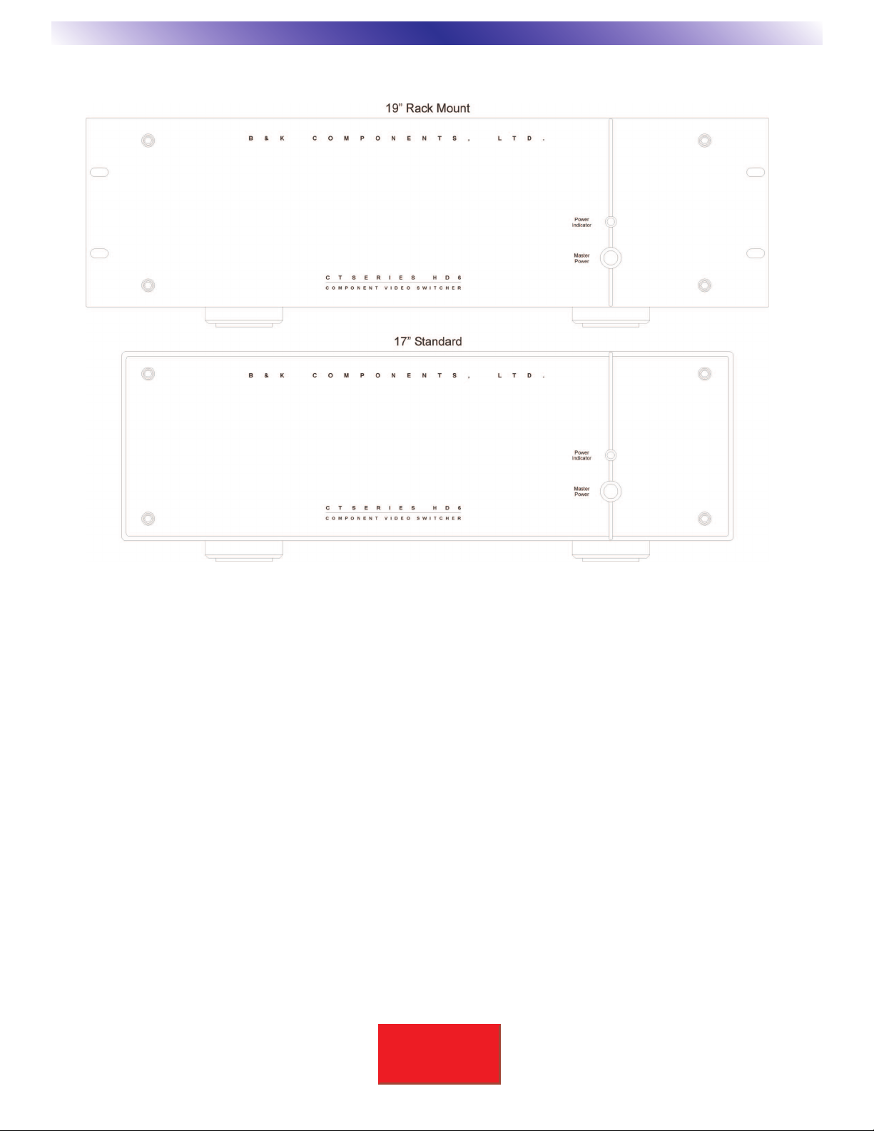
Faceplate Options
The front face of the HD6 includes an anodized aluminum faceplate available in various configurations. The HD6
front panel is comprised of an LED power indicator and master power On/Off switch.
17” Black faceplate (Standard)
available options
17” Silver
19” Black
19” Silver
FRONT PANEL
5
SBIMPLY ETTER!
BK&
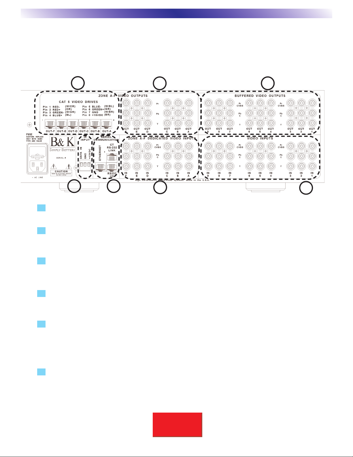
Rear Panel Summary
1 CAT5 Zone Video Outputs - Six zones of video output allow distribution with up to 1080P resolution.
The CAT5 video outputs supply both the power for use with a B&K LB10W or LB20F CAT5 --> RCA external
conversion module and differential video drive for for up to 500 feet.
2 RCA Zone Video Outputs - Six zones of video output, Red, Blue and Green RCAs allow component
video drive for up to 150 feet.
3 Buffered Video Source Outputs - Buffered video outputs will pass video signals connected to the
source inputs 1-9. Unity gain amplified signals essentially eliminate signal degradation and allow easy
cascading of multiple units.
4 Common Video Source Inputs - Up to 9 high definition component video sources may be distributed
throughout any of the six video zones. Composite video (CVBS) and S-Video (Y-C) are transcoded to
component video (Y, Pr, Pb)
5 Dedicated Video Source Inputs - Each of the six video zones has one local high definition source.
Local source connections must be home run to the connections indicated by the letter of the zone, i.e. IN
A. Selectable auto switching is available for use with these inputs when linked to a CT Receiver.
6 Serial Communication Ports - The HD6 is normally controlled via serial communication sent from
the linked CT Receiver.
CT RS-232 LINK - Connects to a CT Receiver RS-232 RJ-45 jack, use straight through cable.
RS-232 I/O - Standard serial in/out. Connect RS-232 controllers here.
ETHERNET - Future control applications and flash memory upgrades.
7 IR Input - A single 3-pin Phoenix-style connector is provided for connecting an external IR ‘eye’ or
Keypad to the HD6. Allows control of the HD6 for simple stand-alone applications where IR is the only
source of real-time control. A 12VDC, 200mA power output is supplied.
HARDWARE DESCRIPTION
123
4
5
6
7

6
SBIMPLY ETTER!
BK&
Placement and Ventilation
As with other advanced video components, the HD6 video processor does generate heat and it is advised to
allow at least 2" of free air space above the unit. If built into a rack, please insert at least one rack space of vent
panel immediately above the unit.
Default Operation
The HD6 is designed for simplicity and functionality right out of the box. The HD6 is designed to be linked to a
B&K CT Series Receiver all settings are automatically configured once the HD6 is powered on. No further setup
programming is required when the HD6 is linked to a B&K CT Receiver. For use in a stand alone installation the
HD6 may be configured using our BKcSuite software setup application.
Connection Strategy
Connecting an HD6 may be a daunting task at first glance. However, the secret to a great looking and easy to
service installation is to be as deliberate as possible. Always make the installation SERVICEABLE as well as
neat! It is recommended to dress wires in groups according to purpose:
• AC Power lines tied together and attached to the cabinet/rack on the opposite side of the signal
cabling. Any component without enough slack in the power wire to enable rotating it or extracting it
should have its length extended with a dedicated extension cord.
••CAT5 cables should be labeled for the appropriate zone or interface, tied, and run together.
••RCA cables should be labeled for the appropriate zone and tied together.
• Combine Keypad/IR Sensor cables together with any Dedicated Zone Input cables that originates in
another zone. Tie each Zone Control cable together with its dedicated source. Tie everything together,
make sure there is a service loop of free cable and dress on the opposite side of the AC Power cables.
•• Combine all cables coming from the sources, label each cable and connect them to the nine inputs.
•• Combine all buffered outputs for use with other preamplifier / receivers units in the system.
•• If you are utilizing any external power amps, combine the zone line outputs and connect to each
amplifier in turn.
Always leave enough slack in the ends of the cable so that the HD6 may be rotated in its shelf or pulled out of
the shelf. Don't leave all the wires tied down so tightly as to make it difficult to rotate or remove components.
HARDWARE CONNECTIONS

7
SBIMPLY ETTER!
BK&
AC Power and Line Fuse
Before connecting any cables, verify that the HD6 powers up. Check functionality of the HD6 by connecting the
AC power cord and powering on the unit with the main power button. Check the front panel LED for illumina-
tion. Disconnect the AC power cord at the rear of the HD6 for safety. You may re-connect once all system unit
connections are complete.
If you need to check the fuse, follow this procedure:
1Power off the unit and unplug the power cord.
2Push up on the fuse release tab.
3Pull the entire fuse holder out.
4Remove the fuse from the fuse holder and measure the fuse with a meter.
You may not be able to tell if it is blown by looking at it.
5Replace only with a fuse of same type and value. The HD6 requires a 2A
Slow-Blow fuse for main A/C.
COMMON VIDEO SOURCE CONNECTIONS
The HD6 is designed to accommodate three types of video source devices: composite video, S-Video and
component video. Component video is passed directly to the appropriate zone output. When a composite or
S-Video is selected, it is converted (transcoded) to component and passed on to the appropriate zone for simul-
taneous distribution out both the RCA and CAT5 Outputs.
Video resolution remains unaltered at all times - and no video scaling is applied.
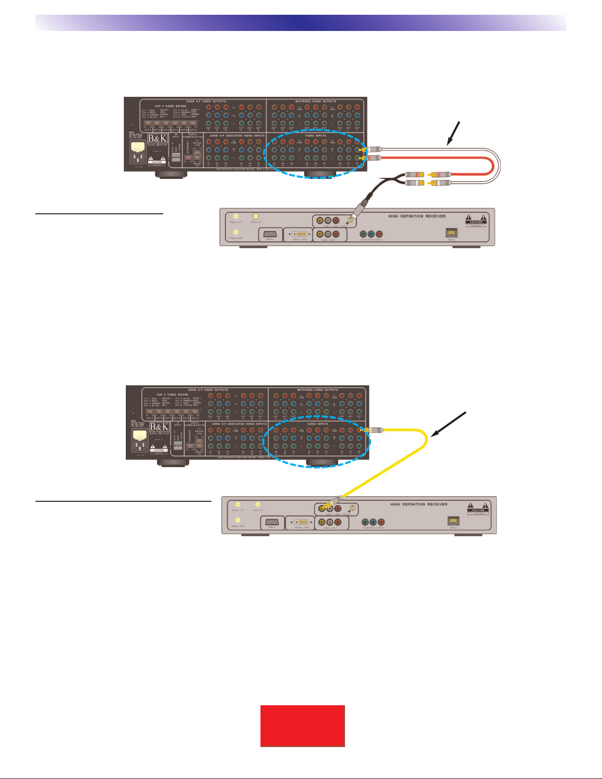
Component Video Connection
Each source that is to be shared throughout the system should be connected to one of the Common Video
Source Inputs. Up to nine sources may be shared throughout any zone in an HD6 system. For use with compo-
nent video sources, connected each device according to the diagram above. Simply connect the three RCA
connections from the component video output of the source to one of the nine common source inputs labeled
IN1 - IN9.
Green is labeled Y, Red is labeled Pr, Blue is labeled Pb.
HARDWARE CONNECTIONS
Component Video Connection
CAUTION: FOR CONTINUED
PROTECTION AGAINST RISK
OF FIRE REPLACE ONLY WITH
SAMETYPEANDVALUEFUSE
8
SBIMPLY ETTER!
BK&
S-Video Source Inputs
S-Video Connection
For use with S-Video, the S-Video (Y-C) signal must first be split into separate RCAs, one for Y and one for C.
Y video must connect to the Green RCA input connector and C video must connect to the Blue RCA input
connector. An adapter similar to the one pictured above is typically used. The HD6 will automatically select
S-Video when it is detected on any common source input IN 1 through IN 9 or dedicated zone input IN A through
IN F. S-Video is converted (transcoded) to component for simultaneous distribution out both the RCA and CAT5
zone outputs.
Video resolution will remain unchanged when transcoding from S-Video to component.
Composite Video Connection
For use with composite video, the composite video signal must be connected to the Red RCA input connector.
The HD6 will automatically select composite video when it is detected on any common source input IN 1 through
IN 9 or dedicated zone input IN A through IN F. Composite video is converted (transcoded) to component for
simultaneous distribution out both the RCA and CAT5 zone outputs.
Video resolution will remain unchanged when transcoding from composite video to component.
HARDWARE CONNECTIONS
Convert S-Video to RCA
HD6 S-Video Connection
Blue = C
Green = Y
HD6 Composite Video Connection
Red = Composite Video (CVBS)
Common Source Inputs
Composite video connection
Common Source Inputs

9
SBIMPLY ETTER!
BK&
Dedicated Video Source Inputs
Dedicated source inputs should be used for sources that are intended for use in only one zone. When linked to
a CT Receiver, the dedicated source inputs have the capability to be auto-selected when video presence is
detected. In addition when a zone’s current state is off, video detection may also be set to power on the zone.
Once the video signal is no longer detected, the zone will return to its previous state. The dedicated source input
auto-selection may be disabled if desired. Each of the 6 dedicated inputs are referred to by the zone letter they
correspond to, i.e. IN A = Zone A. All dedicated inputs accommodate component video, S-Video and composite
video in the same fashion as the common video source inputs 1 through 9. No video scaling is applied to
dedicated input signals.
BUFFERED VIDEO SOURCE OUTPUTS
One buffered line output is provided for each source input, IN 1 through IN 9. Sometimes referred to as loop
through outputs, the buffered video outputs pass the video present on the nine source inputs. The buffered video
output is designed to be terminated by the 75 ohm input stage of another device. The buffered outputs allow
easy cascading of multiple units and minimize signal degradation that might occur with other external splitters
and adapters. For use with composite or S-Video, you need only connect to the appropriate Red (composite) or
Green (Y) and Blue (C) (S-Video). However, for future expansion, you may wish to loop through all buffered
outputs using standard RCA (RGB) cables.
HARDWARE CONNECTIONS
Dedicated Inputs
IN A - IN F
HD6 #1
Source
Buffered Video signals
HD6 #2
10
SBIMPLY ETTER!
BK&
ZONE VIDEO CONNECTIONS
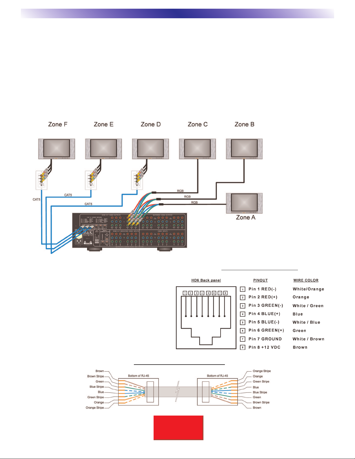
Zone Video Outputs
The selected video in each zone is routed to the appropriate Zone A-F video out. Each of the HD6’s six zones
provide simultaneous video distribution for use with standard RCA cable and Category 5e (CAT5) cable. RCA
terminated video cable works best with distribution runs under 150 feet. Category 5e cable allows differential
video runs of up to 1000 feet. The HD6 CAT5 video drive allows direct connection to B&K LB10W and LB20F
modules for use in converting the video signal back to RCA. The LB10W is for use with a decora wall mount
plate. The LB20F is a fully enclosed box for use where mounting in a wall plate is not possible. The diagram
below shows the HD6 connected using RCA termination in zones A-C, and CAT5 termination with LB10W CAT5
-> RCA local decora video conversion modules in zones D-F.
CAT5 Video Drive Pinout
CAT5 RJ-45 pinouts use the T568B standard. See the
figure at right. Each color twisted pair carries the differ-
ential video signal to the corresponding video output.
For use with Category 5e cable up to 500 feet, Pin 7
and 8 will directly power a B&K LB10W or LB20F
module without the need for an external power supply.
Use of other CAT5 connection standards may result in
increased crosstalk between Y, Pr, Pbsignals with
associated video degradation.
Note: DC power on Pin 7 and 8 is intended only for use
with a B&K LB10W or LB20F module.
HARDWARE CONNECTIONS
Typical CAT5 wire termination
CAT5 RJ-45 Video Pinout

11
SBIMPLY ETTER!
BK&
Transcoding - Video transcoding is the process of converting one video format to another. Video transcoding
is a technology brought about by the need to integrate different video formats. Video transcoding allows different
video formats to be viewed on one video monitor without changing the montor’s settings.
Both S-Video and composite video are transcoded for use with the RCA and CAT5 video drive outputs.
Component video will pass up to 200MHz video bandwidth.
CAT5 -> RCA Zone Video Conversion Modules
When distributing video using the CAT5 video drive outputs, B& K offers two
types of CAT5 -> RCA video conversion modules to convert the signal back
to standard RCA termination. The LB10W decora wall plate may be used to
mount on a wall near the video monitor. The compact LB20F traditional box
type design may rest on a shelf, be mounted behind a rack or even to the
back of the video monitor. Both modules function identically.
LB10W - a decora wall plate conversion module may be installed
into any standard decora wall mount plate. The HD6 CAT5 video
drive cable must always connect to the Master Input on the back
of the first video conversion module. For use with additional slave
modules, the slave output from the first device must connect to
the next conversion module’s Master Input. A small flat blade
screwdriver may be used to adjust the Video EQ trim on the front
panel to match the total installed length of Category 5e cable.
LB20F- a closed box conversion module allows for a myriad of
mounting options. The HD6 CAT5 video drive cable must always
connect to the Master Input on the back of the first video conver-
sion module. A small flat
blade screwdriver may be used to adjust the Video EQ on the front panel
to match the total length of Category 5e cable 0 to 1000 Feet.
HARDWARE CONNECTIONS
LB20F Video
Conversion Module
Master Input
Slave Output
For use with up to 500 feet of Category 5e cable the LB10W or
LB20F module may be powered directly from the HD6 CAT5
Video Drive cable via the modules Master Input. For use with
greater than 500 feet of category 5e cable, an external power
source of 12VDC is required.
Note: All slaved video conversion modules require an external
power supply and will not pass video unless an external
12VDC power source is connected.
Additional Slave Monitors - the LB10W and LB20F provide RJ-45 slave outputs to connect
additional monitors displaying identical video. Simply connect the slave output of one
module to the master input of the next. Any number of monitors may be connected in this
manner so long as the total cable run from the HD6 to the last monitor does not exceed 1000
feet. LB10Ws and LB20Fs may be freely mixed in master/slave configurations. When using
the slave monitor capability, ALL LB10Ws and LB20Fs must each be individually powered.
The slave output is not active when the module is powered over CAT5 from the HD6. Nor
does the slave output provide power for the next module.
12
SBIMPLY ETTER!
BK&
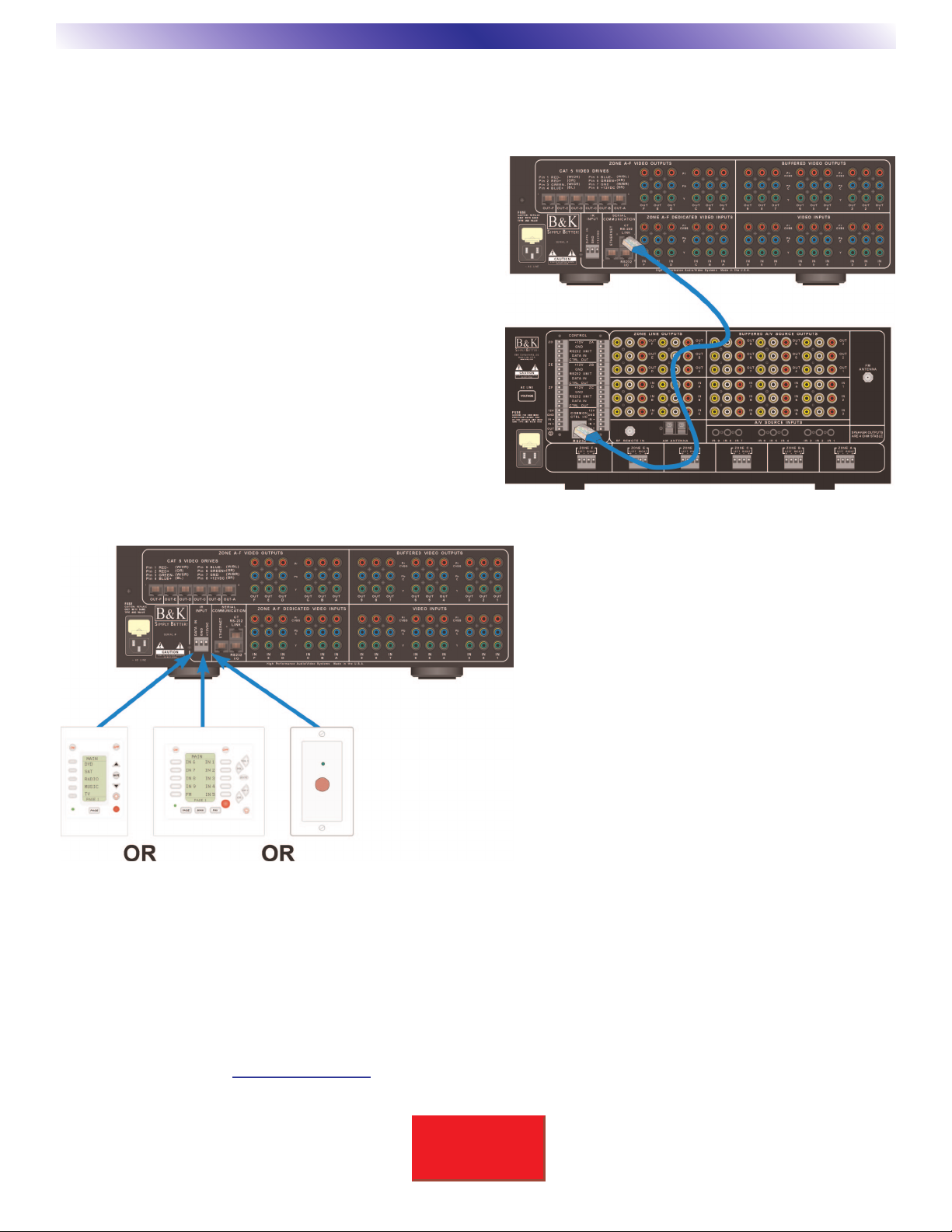
Connection with a CT Series Receiver
The HD6 is designed to operate seamlessly with a CT
Series Receiver. Simply connect the HD6's CT RS-232
LINK connector to the CT's RS-232 connector using a
straight trough CAT5 cable. At power up, the HD6 will
learn all of it's settings from the CT. No additional HD6
setup is required. The LINKING process takes about 15
seconds.
When connected in this manner, the HD6 will stay in sync
with the CT Receiver for keypad and IR messages.
Dedicated input and page/event settings that depend on
video detection will continue to work as expected even
though the video is connected to the HD6 instead of the
CT. Refer to the CT manual for details on dedicated
inputs and page/events.
Stand-Alone Operation using IR or
Keypad
In the absence of a CT Receiver, the HD6 may
be operated directly with an IR eye or keypad.
The HD6 contains no internal IR eye. An
external eye or keypad must be connected for
operation in this configuration.The connection is
made through a 3-pin phoenix style connector.
The connector provides +12V at up to 200mA to
power an external eye or keypad and an IR input
compatible with IR data between +5 and +12
volts. This is strictly a one-way connection. The
HD6 is not capable of providing display feedback
or page jumps on the keypad.
From the factory, an HD6 has zones A-F set to
code-sets 11-16, respectively. And it will also
respond to code-set 0 - whole house. Refer to
"Code-Set Description and Overview" on page
19. These default settings may be changed
using BKcSuite Group Code-Set - see page 20.
Stand-Alone Operation over RS-232
In the absence of CT Receiver, the HD6 may be operated directly with an external controller or PC. Simply
connect the controller to the HD6's main RS-232 I/O connection. See "Connection to a PC" on page 16 for
details on making this connection to a standard RS-232 connector. Leave the CT LINK unconnected. In this
configuration the controller will "see" the HD6 and be able to control it directly. See the HD6 BKC-DIP Product
Specific Appendices for detailed information on setup and control of the HD6 over RS-232. There are also
examples of common RS-232 command and control messages on page 24 of this manual. Additional documen-
tation may be found at www.bkcomp.com, or in the documents folder for use with BKcSuite.
COMMAND AND CONTROL
CT RS-232 LINK
IR Device Communication
Straight through CAT5
13
SBIMPLY ETTER!
BK&
Press buttons slowly. The MZ-128 will not respond to rapid button presses while in setup.
Code-set 128
Code-set 128 is a special IR code-set which allows control only from a Hardware Zone Input
Port. Code-set 128 will not control an HD6 via any IR receiver.
Code-set 999 [B & K ALL Commands]
[ON] [B&K] B & K POWER ON
OFF B & K POWER OFF
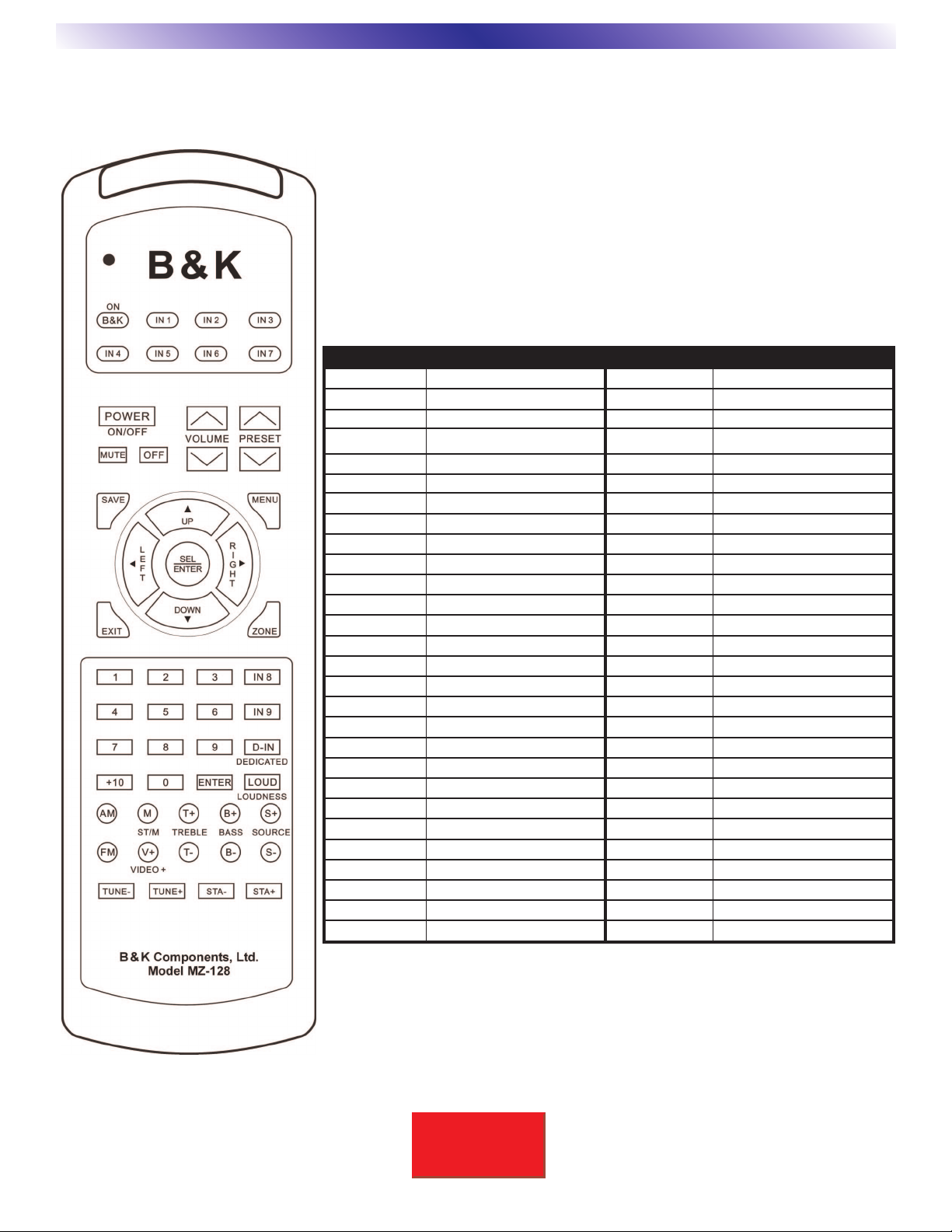
IR REMOTE CONTROL
The MZ-128 Remote Controller has multiple functions:
1) The MZ-128 Remote Controller may be used to control and setup B&K products.
2) The MZ-128 may be used as a source of IR for use in programming learning keypads etc...
3) The MZ-128 may be used to directly control a single zone of an HD6 with an external IR
eye or keypad connected.
Note: No remote or keypad will function directly with the HD6 while it is LINKED to a CT Receiver.
Send IR / Keypad messages directly to the CT Receiver.
MZ-128 CT Series IR Remote Controller
Setup the MZ-128 to use a discrete B & K code-set:
1) Install 4 AAA batteries into the remote. Observe polarity.
2) Press and hold the B & K and MUTE buttons simultaneously for two seconds. The LED will
light up solid red and stay illuminated.
3) Enter the desired B & K three digit code-set. Always use three digits (i.e. 0 1 1)
4) Press the B & K button again to confirm setup. The red LED should blink three times when
the IR code has been successfully programmed.
MZ-128 Button HD6 Function MZ-128 Button HD6 Function
B&K POWER ON SAVE SAVE
POWER POWER TOGGLE MENU MENU
MUTE No Function LEFT LEFT
OFF POWER OFF RIGHT RIGHT
VOLUME UP No Function SEL / ENTER SELECT / ENTER
VOLUME DN No Function UP UP
PRESET UP No Function DOWN DOWN
PRESET DN No Function EXIT EXIT
IN 1 IN 1 ZONE ZONE SELECT
IN 2 IN 2 1 1
IN 3 IN 3 2 2
IN 4 IN 4 3 3
IN 5 IN 5 4 4
IN 6 IN 6 5 5
IN 7 IN 7 6 6
IN 8 IN 8 7 7
IN 9 IN 9 8 8
D-IN DEDICATED ZONE INPUT 9 9
AM No Function +10 +10
FM No Function 0 0
MNo Function ENTER SELECT / ENTER
V+ VIDEO SOURCE UP LOUD No Function
T+ No Function
T- No Function
B+ No Function TUNE - No Function
B- No Function TUNE + No Function
S+ SOURCE UP STA - No Function
S- SOURCE DOWN STA + No Function

14
SBIMPLY ETTER!
BK&
BKcSuite Setup
Setup Using a PC and BKcSuite
B& K Tool Suite may be installed using the CD-ROM included with the HD6 Transcoding Video Switcher. The
software is also available online at www.bkcomp.com. Your PC should be equipped with a CD-ROM or DVD
drive. B& K Tool Suite includes software for setting up B & K Receivers, Preamplifiers, SR10.1 remote, and
CK1.2 / CK1.1 Keypads and Video Switchers.
The installation path for BKcSuite is [c:/program files/B & K Components Ltd/BkcSuite.exe].
***Warning - PC requirements - 128MB RAM, Pentium grade or better processor, Windows 98SE operating
system or greater. (Exception- BKcSuite may not be compatible on some Windows NT machines) ***
Note: This section applies only if it is desired to operate the HD6 in a stand-alone configuration.
Do not perform this setup if the HD6 is to be connected to a CT Series Receiver.
Instead, set up the CT Receiver as desired - refer to the CT Receiver manual. The CT setup may be set either
stand-alone or connected through the HD6.
15
SBIMPLY ETTER!
BK&
BKcSuite Setup
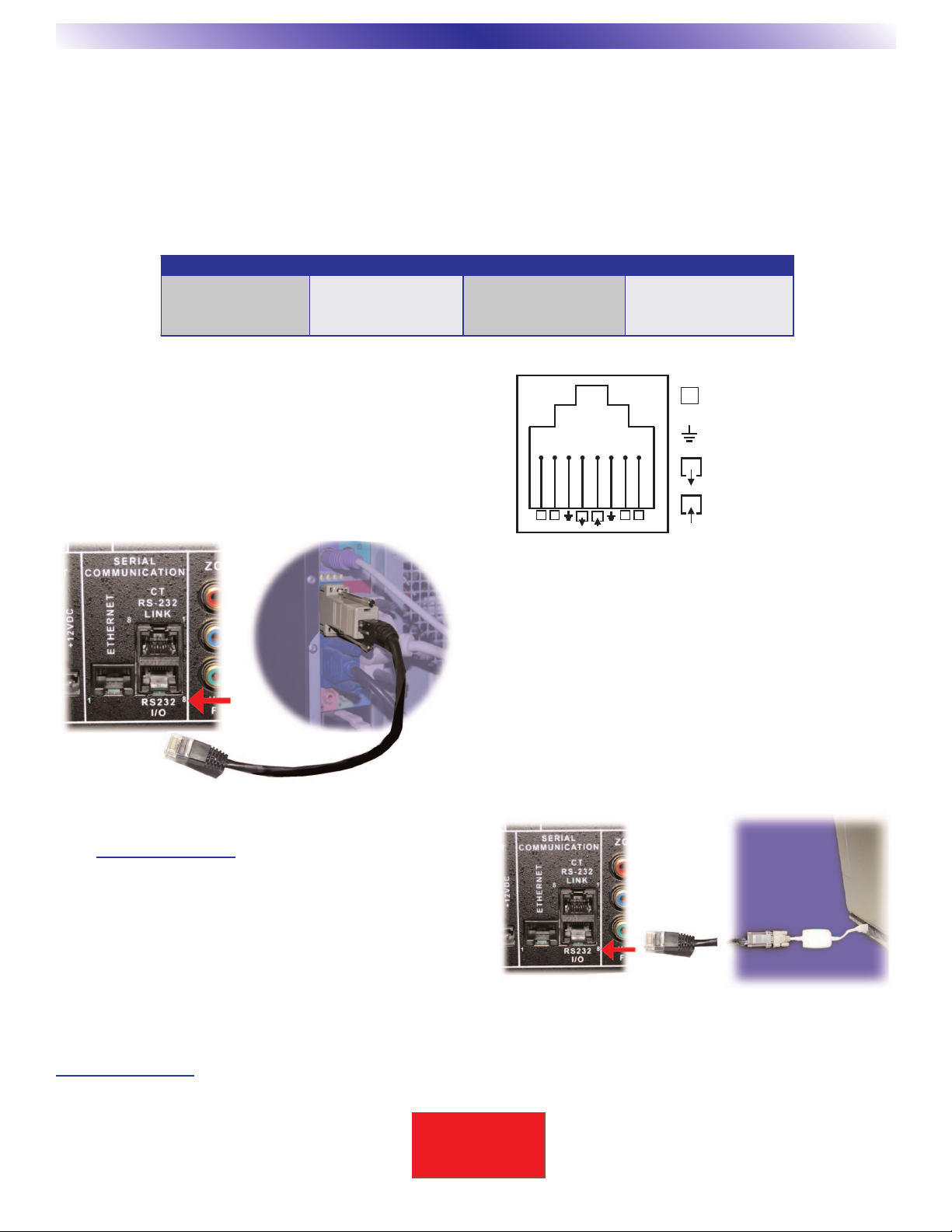
Connection to a PC
The HD6 requires an RS-232 computer connection for use with RS-232 BKcSuite setup. Currently many modern
computers and laptops do not come equipped with an DB-9 RS-232 serial port. If your computer only has a USB
style serial port, you will need to obtain a USB to DB-9 RS-232 serial port adapter cable.
B& K has available a pre-made adapter (B&K p\n 13290) for use in converting a DB-9 serial port for use with the
HD6 RJ-45 RS-232 I/O port. The adapter allows a standard CAT5 network cable to be used to link the PC and
HD6. Shown below is the pin configuration of the HD6 RJ-45 RS-232 I/O serial port for use with a DB-9 or DB-25:
Computer RS-232 Connection
As shown below, connect a DB-9 RS-232 to RJ-45 adapter
(B&K p\n 13290) into an available DB-9 RS-232 port on the
back of the computer. Next, connect one end of a “straight-
through” RJ-45 terminated CAT5 cable into the adapter.
HD6 RS-232 I/O Connection
Next, connect the remaining end of the RJ-45 CAT5
cable into the HD6 RS-232 I/O serial port.
USB to Serial Adapter
USB to serial adapters are a convenient solution for
connecting to a computer that has no available DB-9
type serial port. Install any required software drivers and
note the com port the USB Adapter is set to use. Once
your COM settings are determined, run BKcSuite and set
the appropriate port settings for a simple and easy setup.
Ethernet
Visit www.bkcomp.com for availability of HD6 Ethernet
software support. The HD6 rear panel ETHERNET port
requires a standard CAT5 straight through network cable
for connection to a network router. A CAT5 crossover
cable is required for direct connection to a PC.
BKcSuite Installation
Determine if BKcSuite has previously been installed for use with another B&K product. If yes, visit
www.bkcomp.com and update BKcSuite for use with the HD6. If no BKcSuite has been installed, please insert
the CD supplied with the HD6 and continue with the HD6 setup.
DB9
DB25
Function
RJ45 Connection
Pin 3
Pin 2
Host Transmit
To RJ45 Red
Pin 2
Pin 3
Host Receive
To RJ45 Green
Pin 5
Pin 7
Host Ground
To RJ45 Black
NCNC NCNC
TX
RCV
NC
TX
RCV
No Connection
RS-232 Host Transmit
RS-232 Signal Ground
RS-232 Host Receive
16
SBIMPLY ETTER!
BK&
BKcSuite Setup
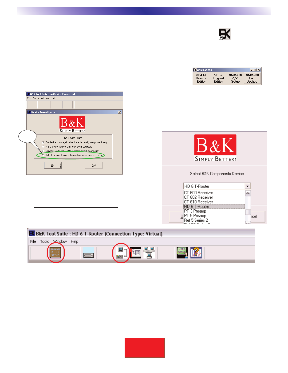
BKcSuite Setup and Overview
During the BKcSuite software install, BKTask was automatically installed as a shortcut
icon on the desktop [BKTask icon (grey)]. Make sure all other applications which use the
serial port are closed before opening the taskbar. BKcSuite software has the capability to connect in real-
time (live) to any of our software controlled preamplifiers, receivers and switchers. However, to avoid possible
system compatibility errors it is recommended that all setup be performed virtually. Once a setup file has been
created, connect to the unit and open the saved files. Typical PC setup should follow the described procedure:
1. DO NOT CONNECT UNIT TO COMPUTER. This is
considered virtual mode. Open BKcSuite A/V Setup from BKTask.
2. When Tool Suite is first opened, the Device Investigator
automatically scans to find a connected B& K product.
Choose “select product for operation without a connected
device.”
3. Choose the product you wish to work with.
4. Create and save the system setup file using the
Advanced Setup menu of in BKcSuite.
5. Connect the PC to the B&K product and establish a
live connection by running the device investigator.
6. Once a live connection is established, open the previously created file. When the file is opened,
BKcSuite will send all settings to the B& K product.
Note: While a live HD6 connection is established with a PC, any changes made in BKcSuite will immediately
update the unit. As good practice, B&K recommends all important BKcSuite HD6 system settings be backed up
with an appropriate name on a computer. HD6 BKcSuite system settings are saved using a .bks file extension.
Click
Here!
Device Investigator
17
SBIMPLY ETTER!
BK&
BKcSuite Setup
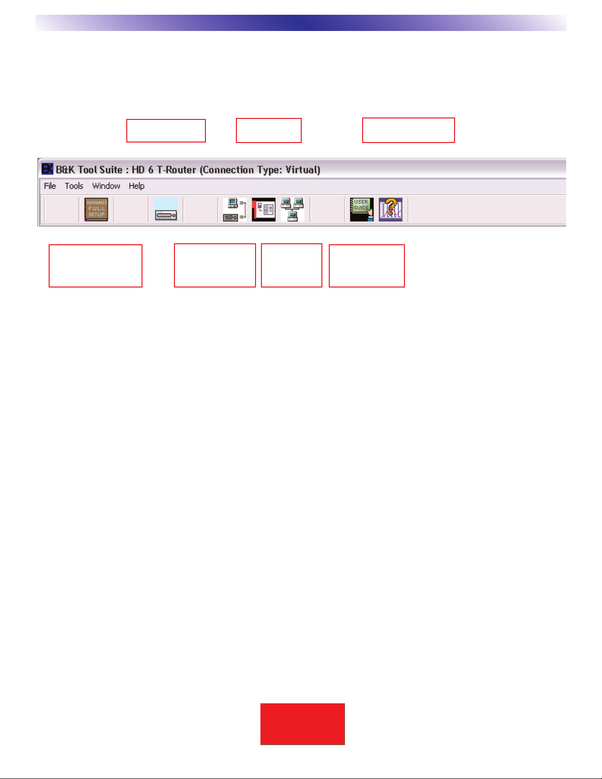
BKcSuite Task Bar Explained
Once you have chosen the HD6 T-Router, BKcSuite displays a tool bar of icons (applications) for with setup and
configuration. Use the mouse to select an icon on the tool bar to activate the appropriate application. The HD6
setup applications are described below:
Open the Advanced System
Editor to program the system
parameters of your HD6.
Select another B&K
Virtual Product to setup.
Run the Device
Investigator so that you
may connect to the HD6
to upload or download
your setup files.
Get information about your
current connection B&K
Device connection
Select a server to
connect to the
internet. (currently
not supported.)
Open one of B&K’s user
manuals or info sheets
using Adobe Reader.
(PDF library)
View / Set comm
port communication
properties

18
SBIMPLY ETTER!
BK&
BKcSuite Setup
Code-set Description and Overview
B& K uses discrete code-sets for command and control of all of its audio/video zones. Code-sets range from
code 0-0-0 (zero zero zero) to 1-2-8. This is the same practice that satellite manufacturers use so that one
remote controller could control three identical satellites. The satellites are first set (via switches or on-screen
menus) to be either an A, B or C satellite. When the remote control is set to IN 1 only IN 1 responds and so on.
In the advanced setup menu of the HD6, code-sets are assigned to control each zone. B&K applies this theory
to each of its zones. Once codes have been assigned, functions like selecting video IN 2 in Junior's room from
the Kitchen keypad is possible. Code-sets may also be used to control a group of zones (such as upstairs or
party modes) or control the whole house (all zones) using code-set 0-0-0.
Code-set 1-2-8 is a special case for use with IR data commands sent directly into a CT Receiver’s IR data in
(keypad) port. The HD6 must be linked to a CT Receiver to use this feature. The CT Receiver monitors which
of the six available Zone IR Data ports that the IR command was received in. The CT Receiver will only process
a code-set 1-2-8 command in the hardware zone that it was received in. Thus, when a keypad or IR controller
is connected to a hardware Zone (A-F) all devices may be programmed identically using code-set 1-2-8 and
control only the hardware zone it is connected to. However, a more powerful and versatile install may be realized
by utilizing other discrete code-sets to enable any keypad to control any zone, any group of zones or the whole
house. Note any front panel code-set 1-2-8 commands received will be ignored and not processed. By design
the intent of a code-set 1-2-8 is to allow a B&K device to very easily be controlled by an external IR data
controller connected to a Zone input port and control only the directly connected zone.
B& K created 128 different sets of the same CT Receiver commands. These commands also work with other
B& K products assigned to the same code-set.
Each code-set differs from the next only in the initial IR code-set identification or prefix, i.e. 11 - Power On. This
allows a way for any hardware zone set to use code-set 11 to be Powered On independent from which zone
received the code-set 11 Power On command. Thus, any zone may control any other zone (or group of zones)
by programming a remote control or a keypad with the appropriate set or sets of codes from the following
choices:
Code-set 000 Controls ALL zones simultaneously. (Multi Zone and Home Theater)
Code-set 001-127 May be utilized for use with groups or independent zone operation. (Discrete)
Code-set 128 Controls only the hard-wired IR Data Input zone receiving the command.
Code-set 999 For use with a special set of ‘B& K ALL’ commands (Multi Zone and Home Theater)
Other manuals for HD6
2
Table of contents
Other B&K Switch manuals


