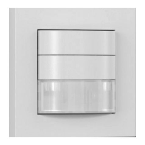
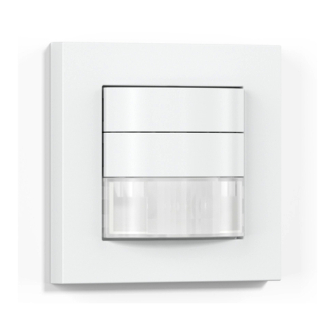
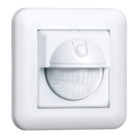
STEINEL IR 180 UP easy User manual

- 2 -
STEINEL Vertrieb GmbH
Dieselstraße 80-84
33442 Herzebrock-Clarholz
Tel: +49/5245/448-188
www.steinel.de
Contact
www.steinel.de/contact
110075506 03/2020_A Technische Änderungen vorbehalten. / Subject to technical modification without notice.
IR 180 UP easy
IR 180 AP easy
LV
LT
EE
HR
SI
RO
PL
SK
CZ
HU
TR
GR
NO
FI
DK
SE
PT
ES
IT
NL
FR
GB
DE
STL-11104-20_IR180_85x120mm.indd 1 19.03.20 07:23
RU
CN
BG

- 2 - - 3 -
3
...
3.1
3.2
Textteil beachten!
Follow written instructions!
Dodržujte písemné pokyny!
Dodržiavajte písomné informácie!
Postępować zgodnie zinstrukcją!
Respectați instrucțiunile următoare!
Upoštevajte besedilo!
Pridržavajte se uputa!
Järgige tekstiosa!
Atsižvelgti į rašytines instrukcijas!
Pievērsiet uzmanību teksta daļai!
Соблюдать текстовую инструкцию!
Прочетете инструкциите!
遵守文字说明要求!
DE. . . . . . 14
GB . . . . .24
CZ. . . . . . 33
SK. . . . . .42
PL . . . . . .51
RO . . . . .60
SI . . . . . .69
HR . . . . . 78
EE. . . . . . 87
LT . . . . . .96
LV . . . . .105
RU . . . . 114
BG . . . .123
CN . . . .132

- 4 - - 5 -
3.3
81
81 57
3.4
82
72 67
3.5
H
CB
GF
D
E
A
3.6
CB
I
H
D
E
F
A
G

- 6 - - 7 -
4.2
L
LL
N
PE
N L´L N
I
O
4.3
L
LL
N
PE
N L´L N
N L´L
I
O
5
3.7
max. 8 m
1,1 m
4
4.1
L
LL
N
PE
N L´L N
I
O

- 8 - - 9 -
5.1
5.2
5.3
5.4

- 10 - - 11 -
5.5
5.6
5.7
5.8
I
O
6

- 12 - - 13 -
6.1
2.
1.
6.2
6.3
5 min.
5 sec.
30 min.
LED ON/OFF
CB
H

- 14 - - 15 -
DE
1. Zu diesem Dokument
Bitte sorgfältig lesen und aufbewahren!
–Urheberrechtlich geschützt. Nachdruck, auch auszugsweise,
nur mit unserer Genehmigung.
–Änderungen, die dem technischen Fortschritt dienen, vorbehalten.
–Alle Produktmaße in mm.
Symbolerklärung
!
Warnung vor Gefahren!
...
Verweis auf Textstellen im Dokument.
2. Allgemeine Sicherheitshinweise
!
Vor allen Arbeiten am Sensorschalter die
Spannungszufuhr unterbrechen!
• Bei der Montage muss die anzuschließende elektrische Leitung spannungs-
frei sein. Daher als erstes Strom abschalten und Spannungsfreiheit mit einem
Spannungsprüfer überprüfen.
• Bei der Installation der Sensorschalter handelt es sich um eine Arbeit an
der Netzspannung. Sie muss daher fachgerecht nach den landesüblichen
Installationsvorschriften und Anschlussbedingungen durchgeführt werden
(z.B. DE: VDE 0100, AT: OVE-EN 1, CH: SEV 1000).
3. IR180UPeasy/IR180APeasy
Bestimmungsgemäßer Gebrauch IR180UPeasy:
–Sensorschalter zur Unterputzmontage in trockenen Innenräumen.
Bestimmungsgemäßer Gebrauch IR180APeasy:
–Sensorschalter zur Aufputzmontage in feuchten und trockenen Innenräumen.
Die Sensorschalter sind mit einem Pyro-Sensor ausgestattet, der die unsicht-
bare Wärmestrahlung von sich bewegenden Körpern (Menschen, Tieren, etc.)
erfasst. Diese registrierte Wärmestrahlung wird elektronisch umgesetzt und ein
angeschlossener Verbraucher (z. B. eine Leuchte) wird eingeschaltet.
Durch Hindernisse, wie z. B. Mauern oder Glasscheiben, wird keine Wärme-
strahlung erkannt, es erfolgt also auch keine Schaltung.
Der Sensorschalter ist sowohl für eine 2- als auch für eine 3-Draht-Installation
ausgelegt.
Lieferumfang IR180UPeasy (Abb.3.1)
Lieferumfang IR180APeasy (Abb.3.2)
Produktmaße IR180UPeasy (Abb.3.3)
Produktmaße IR180APeasy (Abb.3.4)
Geräteübersicht IR180UPeasy (Abb.3.5)
A Lastmodul
B Dämmerungseinstellung
C Zeiteinstellung
D Schraubenschaft der Anschlussklemme
E Kabelschacht der Anschlussklemme
F Rahmen
G Sensormodul
H Taster für Lichtfunktion
Geräteübersicht IR180APeasy (Abb.3.6)
A Aufputzgehäuse
B Dämmerungseinstellung
C Zeiteinstellung
D Schraubenschaft der Anschlussklemme
E Kabelschacht der Anschlussklemme
F Lastmodul
G Sensormodul
H Taster für Lichtfunktion
I Abdeckung
Erfassungsbereich (Abb.3.7)
4. Elektrischer Anschluss
Schaltplan Anschluss: Zwei-Draht (Abb.4.1)
Schaltplan Anschluss: Drei-Draht (Abb.4.2)
Schaltplan Anschluss: Vernetzung mehrerer Sensorschalter (Abb.4.3)
Die Netzzuleitung besteht aus einem 2- bzw. 3-adrigen Kabel:
L= Phase (meistens schwarz oder braun)
N= Neutralleiter (meistens blau, optional)
L' = Geschaltete Phase (meistens schwarz, braun oder grau)

- 16 - - 17 -
Im Zweifel müssen Sie die Kabel mit einem Spannungsprüfer identifizieren;
anschließend wieder spannungsfrei schalten. Phase (L) und (L') werden an die
Anschlussklemme angeschlossen. Neutralleiter (N) kann optional angeschlossen
werden. Ein Schutzleiter wird nicht benötigt.
Wichtig:
Ein Vertauschen der Anschlüsse führt im Gerät oder Sicherungskasten zu einem
Kurzschluss. In diesem Fall müssen nochmals die einzelnen Kabel identifiziert
und neu verbunden werden.
Eine Parallelschaltung mehrerer Sensorschalter ist möglich. Die maximale an-
schließbare Leistung erhöht sich dadurch nicht. An jedem Sensorschalter muss
der Neutralleiter (N) angeschlossen werden.
5. Montage
• Alle Bauteile auf Beschädigung prüfen.
• Bei Schäden das Produkt nicht in Betrieb nehmen.
• Geeigneten Montageort auswählen unter Berücksichtigung der Reichweite
und Bewegungserfassung.
Montageschritte UP
• Stromversorgung ausschalten (Abb.4.1/4.2/4.3)
• Anschlusskabel am Lastmodul anschließen (Abb.5.1)
–Anschluss 2-Draht (Abb.4.1)
–Anschluss 3-Draht (Abb.4.2)
• Lastmodul in die Unterputzdose schieben (Abb.5.2)
• Lastmodul festschrauben (Abb.5.3)
• Rahmen und Sensormodul auf Lastmodul stecken (Abb.5.4)
• Stromversorgung einschalten (Abb.5.8)
• Einstellungen "6. Funktion"
Montageschritte AP
• Stromversorgung ausschalten (Abb.4.1/4.2/4.3)
• Aufputzgehäuse anschrauben (Abb.5.5)
• Anschlusskabel am Lastmodul anschließen (Abb.5.6)
–Anschluss 2-Draht (Abb.4.1)
–Anschluss 3-Draht (Abb.4.2)
• Lastmodul, Sensormodul und Abdeckung montieren (Abb.5.7)
• Stromversorgung einschalten (Abb.5.8)
• Einstellungen "6. Funktion"
6. Funktion
Werkseinstellungen
Dämmerungseinstellung: 1000Lux (Tageslichtbetrieb)
Zeiteinstellung: 5Sekunden
Für Funktionseinstellungen muss das Sensormodul geönet werden.
• Drücken Sie mit dem Schraubendreher auf die Rastnase und önen Sie die
Klappe (UP). (Abb.6.1)
• Schrauben Sie die Abdeckung ab (AP). (Abb.6.2)
Dämmerungseinstellung (Abb.6.3/B)
Die gewünschte Ansprechschwelle des Sensorschalters kann in Stufen von
2Lux bis 1000Lux bzw. helligkeitsunabhängig eingestellt werden.
Einstellregler : Tageslichtbetrieb (helligkeitsunabhängig)
Einstellregler : Dämmerungsbetrieb (2Lux)
Bei der Einstellung des Erfassungsbereiches und für den Funktionstest bei
Tageslicht muss der Einstellregler auf stehen.
Zeiteinstellung (Abb.6.3/C)
Die gewünschte Leuchtdauer der angeschlossenen Leuchte kann in Stufen von
5Sekunden bis maximal 30Minuten eingestellt werden.
Einstellregler 5s: kürzeste Zeit (5Sekunden)
Einstellregler 5min: 5Minuten
Einstellregler 30min: längste Zeit (30Minuten)
Durch jede erfasste Bewegung vor Ablauf dieser Zeit wird die Nachlaufzeit neu
gestartet. Bei der Einstellung des Erfassungsbereiches und für den Funktions-
test wird empfohlen, die kürzeste Zeit einzustellen.
Hinweis:
Nach jedem Abschaltvorgang ist eine erneute Bewegungserfassung für ca.
6Sekunden unterbrochen. Erst nach Ablauf dieser Zeit kann der Sensorschalter
bei Bewegung wieder Licht schalten.
LED ON/OFF
Wenn die Status-LED als störend empfunden wird, kann sie problemlos aus-
geschaltet werden.

- 18 - - 19 -
Einstellregler kurz (1Sekunde) auf LED ON/OFF stellen.
LED blinkt 1-mal: LED ist eingeschaltet.
LED blinkt 2-mal: LED ist abgeschaltet.
Anschließend muss der Einstellregler wieder auf die gewünschte Zeiteinstellung
gestellt werden. Passiert dies nicht, beträgt die Zeiteinstellung 2Minuten.
Taster für Lichtfunktion (Abb.6.3/H)
Status Licht AN: 1×Drücken
Licht geht aus. Wird keine Bewegung mehr erfasst, läuft die Nachlaufzeit ab und
der Sensorschalter wechselt in den normalen Sensorbetrieb.
Status Licht AUS: 1×Drücken
Licht geht an, auch wenn ausreichend Helligkeit vorhanden ist. Das Licht bleibt
so lange eingeschaltet, bis es der Sensorschalter aufgrund fehlender Bewegung
oder ausreichender Umgebungshelligkeit ausschaltet.
Teach-Modus
Der Teach-Modus speichert den aktuellen Wert der Umgebungshelligkeit, unter-
halb dessen der Sensorschalter zukünftig auf Bewegung reagieren soll.
Wird der Taster für 5Sekunden gedrückt, wird die Helligkeit eingelernt. Dies
erfolgt 5Sekunden nach Loslassen des Tasters, um ein Abschatten des
Helligkeitssensor zu verhindern. Der Eintritt in den Teach-Modus wird durch
einmaliges Blinken der LED angezeigt. Während des Teach-Vorgangs ist
die angeschlossene Leuchte ausgeschaltet. Das Abspeichern des aktuellen
Helligkeitswerts wird durch einmaliges Blinken der LED bestätigt. Danach geht
der Sensorschalter zurück in den Sensorbetrieb und arbeitet mit der neuen
Schwelle. Der Teach-Modus kann beliebig häufig wiederholt werden.
Um den Teach-Modus zu verlassen, betätigen Sie den Einstellregler Dämme-
rungseinstellung.
7. Wartung und Pflege
Dieses Produkt ist wartungsfrei.
Die Oberfläche kann bei Verschmutzung mit einem feuchten Tuch (ohne Reini-
gungsmittel) gesäubert werden.
8. Entsorgung
Elektrogeräte, Zubehör und Verpackungen sollen einer umweltgerechten
Wiederverwertung zugeführt werden.
Werfen Sie Elektrogeräte nicht in den Hausmüll!
Nur für EU-Länder:
Gemäß der geltenden Europäischen Richtlinie über Elektro- und Elektronik-
Altgeräte und ihrer Umsetzung in nationales Recht müssen nicht mehr
gebrauchsfähige Elektrogeräte getrennt gesammelt und einer umweltgerechten
Wiederverwertung zugeführt werden.
9. Herstellergarantie
Herstellergarantie der STEINEL Vertrieb GmbH, Dieselstraße 80-84,
33442 Herzebrock-Clarholz
Wir beglückwünschen Sie zum Kauf Ihres STEINEL-Produkts, das höchste
Qualitätsansprüche erfüllt. Aus diesem Grund leisten wir als Hersteller Ihnen
als Endkunde gerne eine unentgeltliche Garantie gemäß den nachstehenden
Bedingungen: Wir leisten Garantie durch kostenlose Behebung der Mängel
(nach unserer Wahl: Reparatur, Austausch ggf. durch ein Nachfolgemodell oder
Rückerstattung des Kaufpreises), die innerhalb der Garantiezeit auf einem Mate-
rial- oder Herstellungsfehler beruhen. Die Garantiezeit für Ihr erworbenes STEINEL-
Produkt beträgt 3 Jahre und beginnt mit dem Kaufdatum Ihres Produktes. Diese
Herstellergarantie lässt gesetzliche Gewährleistungsansprüche, die Ihnen als
Verbraucher gegenüber dem Verkäufer nach geltendem Recht einschließlich
besonderer Schutzbestimmungen für Verbraucher zustehen können, unberührt.
Die hier beschriebenen Leistungen gelten zusätzlich zu den gesetzlichen
Gewährleistungsansprüchen und beschränken oder ersetzen diese nicht.
Ausdrücklich ausgenommen von dieser Garantie sind alle auswechselbaren
Leuchtmittel. Darüber hinaus ist die Garantie ausgeschlossen:
• bei einem gebrauchsbedingten oder sonstigen natürlichen Verschleiß von
Produktteilen oder Mängeln am STEINEL-Produkt, die auf gebrauchsbeding-
tem oder sonstigem natürlichem Verschleiß zurückzuführen sind,
• bei nicht bestimmungs- oder unsachgemäßem Gebrauch des Produkts oder
Missachtung der Bedienungshinweise,

- 20 - - 21 -- 20 -
• wenn An- und Umbauten bzw. sonstige Modifikationen an dem Produkt
eigenmächtig vorgenommen wurden oder Mängel auf die Verwendung von
Zubehör-, Ergänzungs- oder Ersatzteilen zurückzuführen sind, die keine
STEINEL-Originalteile sind,
• wenn Wartung und Pflege der Produkte nicht entsprechend der Bedienungs-
anleitung erfolgt sind,
• wenn Anbau und Installation nicht gemäß den Installationsvorschriften von
STEINEL ausgeführt wurden,
• bei Transportschäden oder -verlusten.
Die Garantie gilt für sämtliche STEINEL-Produkte, die in Deutschland gekauft
und verwendet werden. Es gilt deutsches Recht unter Ausschluss des Über-
einkommens der Vereinten Nationen über Verträge über den internationalen
Warenkauf (CISG).
Geltendmachung
Wenn Sie Ihr Produkt reklamieren wollen, senden Sie es bitte vollständig und
frachtfrei mit dem Original-Kaufbeleg, der die Angabe des Kaufdatums und der
Produktbezeichnung enthalten muss, an Ihren Händler oder direkt an uns, die
STEINEL Vertrieb GmbH – Reklamationsabteilung –, Dieselstraße 80-84,
33442 Herzebrock-Clarholz.
Wir empfehlen Ihnen daher, Ihren Kaufbeleg bis zum Ablauf der Garantiezeit
sorgfältig aufzubewahren. Für Transportkosten und -risiken im Rahmen der
Rücksendung übernehmen wir keine Haftung.
HERSTELLER
1
3
JAHR
DEU
GARANTIE
5
HERSTELLER
GARANTIE
HERSTELLER
GARANTIE
10. Technische Daten
IR180UPeasy IR180APeasy
Abmessungen (H×B×T) 81×81×57mm 82×72×67mm
Netzanschluss 220-240V, 50/60Hz
Leistungsaufnahme 25mW
Leistung
Glüh-/ Halogenlampenlast
Leuchtstoampen EVG
Leuchtstoampen unkompensiert
Leuchtstoampen reihenkompensiert
Niedervolt Halogenlampen
LED < 2 W
2 W < LED < 8 W
LED > 8 W
Kapazitive Belastung
200W
150W
150VA
150VA
200VA
40W
100W
160W
132µF
Minimale Anschlussleistung mit N: 1W
ohne N: 4W
Montagehöhe 1,1m
Sensorik Passiv Infrarot
Erfassungswinkel 180° mit 90° Önungswinkel
Reichweite max. 8m tangential
Dämmerungseinstellung 2-1000Lux
Zeiteinstellung 5 s - 30min
Temperatur 0 bis +40 °C
Schutzart IP20 IP54

- 22 - - 23 -
11. Betriebsstörungen
Störung Ursache Abhilfe
Sensorschalter ohne
Spannung ■Sicherung hat ausgelöst,
nicht eingeschaltet
■Kurzschluss
■Sicherung einschalten,
tauschen, Netzschalter
einschalten, Leitung
überprüfen mit
Spannungsprüfer
■Anschlüsse überprüfen
Sensorschalter schaltet
nicht ein ■Leuchtmittel defekt ■Leuchtmittel austauschen
Sensorschalter schaltet
nicht ein ■bei Tagesbetrieb,
Dämmerungseinstellung
steht auf Nachtbetrieb
■Sicherung hat ausgelöst
■neu einstellen
■Sicherung einschalten,
tauschen, evtl. Anschluss
überprüfen
Sensorschalter schaltet
nicht aus ■dauernde Bewegung im
Erfassungsbereich
■geschaltete Leuchte
befindet sich im
Erfassungsbereich und
schaltet durch Tempera-
turveränderung neu
■weiterer Sensorschalter
parallel geschaltet und
noch aktiv
■Bereich kontrollieren
■Zeiteinstellung des
anderen Sensorschalters
abwarten
Sensorschalter schaltet
immer EIN/AUS ■geschaltete Leuchte
befindet sich im
Erfassungsbereich
■Tiere bewegen sich im
Erfassungsbereich
■Bereich kontrollieren
LEDs glimmen, flackern ■LEDs reagieren zu
sensibel ■Neutralleiter (N)
anschließen, Leuchtmittel
tauschen
12. LED-Blinkcodes bei Störung
LED-Blinkcode Ursache Abhilfe
1-mal Blinken
jede Sekunde
Betrieb gestört Anschlüsse überprüfen,
Leuchtmittel tauschen,
Neutralleiter anschließen
2-mal Blinken
alle 5Sekunden
Versorgungsspannung
fehlerhaft
Anschlüsse überprüfen,
Leuchtmittel tauschen,
Neutralleiter anschließen
3-mal Blinken
alle 5Sekunden
Überlast, Kurzschluss Anschlüsse überprüfen,
Leistung reduzieren,
Anzahl angeschlossener
Leuchtmittel reduzieren
4-mal Blinken
alle 5Sekunden
Zu hohe Temperatur Leistung reduzieren
5-mal Blinken
alle 5Sekunden
Zu geringe Temperatur Einsatzort überprüfen
Nachdem die Störung behoben wurde, kann der Sensorschalter durch Drücken
des Tasters neu gestartet werden. Nur bei den Temperaturstörungen geht der
Sensor automatisch in den Normalbetrieb über, sobald sich die Temperatur
normalisiert hat.

- 24 - - 25 -
GB
1. About this document
Please read carefully and keep in a safe place.
–Under copyright. Reproduction either inWhole or in part onlyWith our
consent.
–Subject to change in the interest of technical progress.
–All product dimensions in mm.
Symbols
!
HazardWarning!
...
Reference to other information in the document.
2. General safety precautions
!
Disconnect the power supply before attempting any
Work
on the sensor switch.
• During installation, the electric power cable being connected must not be
live. Therefore, switch o the power first and use a voltage tester to make
sure theWiring is o-circuit.
•
• Installing the sensor switch involves work on the mains voltage supply.
This work must therefore be carried out professionally in accordance with
national wiring regulations and electrical operating conditions (e.g.
DE: VDE 0100, AT: OVE-EN 1, CH: SEV 1000).
3. IR180UPeasy/IR180APeasy
Proper use - IR180UPeasy:
–Sensor switch for concealed installation in dry interior spaces.
Proper use - IR180APeasy:
–Sensor switch for surface installation in dry interior spaces and those
exposed to moisture.
The sensor switches are equipped with a pyro sensor which detects the invisible
heat emitted by moving objects (people, animals etc.). The heat detected in this
way is converted electronically into a signal that switches a connected load ON
(e.g. a light).
Heat is not detected through obstacles, such as walls or panes of glass, and will
therefore not activate the light.
The sensor switch is designed for both 2 and 3-wire electrical systems.
Package contents - IR180UPeasy (Fig.3.1)
Package contents - IR180APeasy (Fig.3.2)
Product dimensions - IR180UPeasy (Fig.3.3)
Product dimensions - IR180APeasy (Fig.3.4)
Product components - IR180UPeasy (Fig.3.5)
A Load module
B Twilight setting
C Time setting
D Connecting terminal screw shaft
E Connecting terminal cable duct
F Surround
G Sensor module
H Switch for light function
Product components - IR180APeasy (Fig.3.6)
A Surface-mounting enclosure
B Twilight setting
C Time setting
D Connecting terminal screw shaft
E Connecting terminal cable duct
F Load module
G Sensor module
H Switch for light function
I Cover
Detection zone (Fig.3.7)
4. Electrical connection
Connection wiring diagram: two-wire (Fig.4.1)
Connection wiring diagram: three-wire (Fig.4.2)
Connection wiring diagram: interconnecting several sensor switches (Fig.4.3)

- 26 - - 27 -
The supply lead is a 2 or 3-core cable:
L = phase conductor (usually black or brown)
N = neutral conductor (usually blue, optional)
L' = switched phase conductor (usually black, brown or grey)
If you are in any doubt, identify the conductors using a voltage tester; then
disconnect from the power supply again. Connect phase conductor (L) and (L')
to the terminal. Neutral conductor (N) can be connected to the terminal as an
option. A protective-earth conductor is not required.
Important:
Mixing up the connectionsWill cause a short circuit in the product or your fuse
box. In this case, you must identify the individual conductors once again and
reconnect them.
Several sensor switches can be connected in parallel. This does not increase
the maximum connectable load. The neutral conductor (N) must be connected
at each sensor switch.
5. Mounting
• Check all components for damage.
• Do not use the product if it is damaged.
• Select an appropriate mounting location, taking the reach and motion
detection into consideration.
Mounting procedure for concealed installation (UP)
• Switch OFF power supply (Fig.4.1/4.2/4.3)
• Connect conductors to load module (Fig.5.1)
–2-wire connection (Fig.4.1)
–3-wire connection (Fig.4.2)
• Push load module into the flush-mounting box (Fig.5.2)
• Screw load module into place (Fig.5.3)
• Fit surround and sensor module on load module (Fig.5.4)
• Switch ON power supply (Fig.5.8)
• Settings "6. Function"
Mounting procedure for surface installation (AP)
• Switch OFF power supply (Fig.4.1/4.2/4.3)
• Screw on surface-mounting enclosure (Fig.5.5)
• Connect conductors to load module (Fig.5.6)
–2-wire connection (Fig.4.1)
–3-wire connection (Fig.4.2)
• Fit load module, sensor module and cover (Fig.5.7)
• Switch ON power supply (Fig.5.8)
• Settings "6. Function"
6. Function
Factory settings
Twilight setting: 1000Lux (daylight mode)
Time setting: 5seconds
The sensor module must be opened to make the function settings.
• Press the screwdriver onto the tab and open the flap (concealed installation).
(Fig.6.1)
• Unscrew the cover (surface installation). (Fig.6.2)
Twilight setting (Fig.6.3/B)
The sensor switch response threshold can be set in increments from
2lux to 1000lux.
Control dial set to : daylight operation (independent of ambient light level)
Control dial set to : twilight operation (2lux)
The control dial must be turned to When adjusting the detection zone and
performing the functional test in daylight.
Time setting (Fig.6.3/C)
The time youWant the connected lamp to stay ON for can be set in increments
from 5seconds to a maximum of 30minutes.
Control dial set to 5s: shortest time (5seconds)
Control dial set to 5min: 5minutes
Control dial set to 30min: longest time (30minutes)
The stay-ON time s restarted by any movement before this time elapses.
The shortest time setting is recommendedWhen adjusting the detection zone
and performing the functional test.
Note:
Every time the light switches OFF, it takes approximately 6seconds for the
sensor to start detecting movement again. Only after this time elapses can the
sensor switch turn light ON again in response to motion.

- 28 - - 29 -
LED ON/OFF
If you are irritated by the status LED, it can easily be switched OFF.
Briefly (1 second) set control dial to LED ON/OFF.
LED flashes once: LED is ON.
LED flashes twice: LED is OFF.
The control dial must then be adjusted to the chosen time setting. If this is not
done, the time set is 2minutes.
Switch for light function (Fig.6.3/H)
Light ON status: press once
Light goes out. If no movement is being detected, the stay-ON time elapses and
the sensor switch changes to normal sensor mode.
Light OFF status: press once
Light come ON even in sucient ambient brightness. The light stays switched
ON until the sensor switch turns it OFF because no movement is being detected
or ambient brightness is sucient.
Teach mode
Teach mode saves the current ambient light level below which you do not want
the sensor switch to respond to movement from now on.
Pressing the button for 5seconds programs in the light level. This takes place
5seconds after releasing the button to prevent any shadow being cast over the
brightness sensor. The LED flashes once to indicate that Teach mode has been
selected. The connected lamp is switched OFFWhile the Teach cycle is in pro-
gress. The LED flashes once to confirm that the current ambient light level has
been saved. The sensor switch then returns to sensor mode and operatesWith
the new threshold. Teach mode can be repeated any number of times.
To quit Teach mode, turn the twilight setting control dial.
7. Maintenance and care
This product requires no maintenance.
The surface can be cleanedWith a damp cloth (without detergents) if dirty.
8. Disposal
Electrical and electronic equipment, accessories and packaging must be recy-
cled in an environmentally compatible manner.
Do not dispose of electrical and electronic
equipment as domesticWaste.
EU countries only:
Under the current European Directive onWaste Electrical and Electronic Equip-
ment and its implementation in national law, electrical and electronic equipment
no longer suitable for use must be collected separately and recycled in an
environmentally compatible manner.
9. Manufacturer’sWarranty
This STEINEL product has been manufacturedWith great care, tested for
proper operation and safety in accordanceWith applicable regulations and then
subjected to random sample inspection. STEINEL guarantees that it is in perfect
condition and properWorking order. TheWarranty period is 36 months, starting
from the date of sale to the consumer.WeWill remedy defects caused by
material flaws or manufacturing faults. TheWarrantyWill be met by repair or re-
placement of defective parts at our own discretion. TheWarranty shall not cover
damage toWear parts, damage or defects caused by improper treatment or
maintenance. Further consequential damage to other objects shall be excluded.
Claims underWarranty shall only be accepted if the product is sent fully
assembled andWell packed completeWith receipt or invoice (date of purchase
and dealer’s stamp) to the appropriate service centre or handed in to the deal-
erWithin the first 6 months.
Repair service:
Please ask your nearest service centre how to proceed for repairing faults not
covered by theWarranty or occurring after theWarranty expires.
MANUFACTURER'S
1
3
5
YEAR
GB
WARRANTY
MANUFACTURER'S
YEAR
WARRANTY
MANUFACTURER'S
YEAR
WARRANTY

- 30 - - 31 -- 30 -
10. Technical specifications
IR180UPeasy IR180APeasy
Dimensions (H×W×D) 81×81×57mm 82×72×67mm
Power supply 220-240V, 50/60Hz
Power consumption 25mW
Output
Incandescent / halogen lamp load
Fluorescent lamps, electronic ballast
Fluorescent lamps, uncorrected
Fluorescent lamps, series-corrected
Low-voltage halogen lamps
LED < 2 W
2 W < LED < 8 W
LED > 8 W
Capacitive load
200W
150W
150VA
150VA
200VA
40W
100W
160W
132µF
Minimum connected load with N: 1W
without N: 4W
Mounting height 1.1m
Sensor system Passive infrared
Angle of coverage 180° with 90° angle of aperture
Reach Max. 8 m tangential
Twilight setting 2-1000lux
Time setting 5 s - 30min
Temperature 0°C to +40°C
IP rating IP20 IP54
11. Troubleshooting
Malfunction Cause Remedy
Sensor switchWithout
voltage ■Fuse has tripped, not
switched ON
■Short circuit
■Activate, change fuse,
turn ON mains switch,
checkWiringWith
voltage tester
■Check connections
Sensor switch not
switching ON ■Lamp faulty ■replace lamp
Sensor switch not
switching ON ■Twilight setting in night-
time mode during
daytime operation
■Fuse has tripped
■Reset
■Activate, change fuse,
check connection if
necessary
Sensor switch not
switching OFF ■Continued
movementWithin the
detection zone
■Light is in detection zone
and keeps switching ON
as a result of
temperature change
■Other sensor switch is
connected in parallel and
still active
■Check detection zone
■Wait for time setting of
the other sensor switch
to elapse
Sensor switch always
switches ON/OFF ■Light being operated in
the detection zone
■Animals moving in
detection zone
■Check detection zone
LEDs glowing, flickering ■LEDs responding too
sensitively ■Connect neutral
conductor (N), change
lamp

- 32 - - 33 -- 32 -
CZ
1. Ktomuto dokumentu
Pozorně si jej přečtěte auschovejte!
–Chráněno autorským právem. Dotisk, ičástečný, jen snaším souhlasem.
–Změny, které slouží technickému pokroku, vyhrazeny.
–Všechny rozměry výrobku v mm.
Vysvětlení symbolů
!
Varování před nebezpečím!
... Odkaz na text vdokumentu.
2. Všeobecné bezpečnostní pokyny
!
Před zahájením jakýchkoli prací na senzorovém spínači přerušit
přívod napětí!
• Připojované elektrické vedení nesmí být během montáže pod napětím.
Proto je nejprve třeba vypnout proud apoté pomocí zkoušečky napětí
zkontrolovat, zda je vedení bez napětí.
• Při instalaci senzorového spínače se jedná opráci na síťovém napětí. Musí
proto být provedena odborně podle obvyklých předpisů pro instalaci elektric-
kých zařízení a podmínek jejich připojení dle ČSN (např. DE: VDE 0100,
AT: OVE-EN 1, CH: SEV 1000).
3. IR180UPeasy/IR180APeasy
Používání vsouladu surčením IR180UPeasy:
–Senzorový spínač k montáži pod omítku do suchých vnitřních prostorů.
Používání vsouladu surčením IR180APeasy:
–Senzorový spínač k montáži na omítku do vlhkých a suchých vnitřních
prostorů.
Senzorové spínače jsou vybaveny pyroelektrickým senzorem, který zazname-
nává neviditelné tepelné záření vydávané pohybujícími se těly (osob, zvířat atp.).
Takto zaznamenané tepelné záření je pak elektronicky převedeno na signál
způsobující zapnutí připojeného spotřebiče (např. osvětlení).
12. LED flashing code for malfunction
LED flashing code Cause Remedy
1 flash
every second
Operating malfunction Check connections,
change bulb, connect
neutral conductor
2 flashes
every 5seconds
Faulty power supply Check connections,
change bulb, connect
neutral conductor
3 flashes
every 5seconds
Overload, short circuit Check connections,
reduce output, reduce
number of bulbs con-
nected
4 flashes
every 5seconds
Temperature too high Reduce output
5 flashes
every 5seconds
Temperature too low Check place of use
Once the malfunction has been remedied, the sensor switch can be restarted by
pressing the button. For temperature faults only: the sensor automatically goes
to normal operating mode as soon as the temperature has returned to normal.

- 34 - - 35 -
Poněvadž tepelné záření neprochází překážkami, jako např. zdmi nebo skle-
něnými tabulemi, nedochází vtěchto případech kjeho zaznamenání atedy ani
kzapnutí.
Senzorový spínač je dimenzován jak pro 2, tak i 3vodičovou instalaci.
Rozsah dodávky IR180UPeasy (obr.3.1)
Rozsah dodávky IR180APeasy (obr.3.2)
Rozměry výrobku IR180UPeasy (obr.3.3)
Rozměry výrobku IR180APeasy (obr.3.4)
Přehled zařízení IR180UPeasy (obr.3.5)
A Zátěžový modul
B Soumrakové nastavení
C Časové nastavení
D Dřík šroubu připojovací svorky
E Kabelová šachta připojovací svorky
F Rám
G Senzorový modul
H Tlačítko pro funkci svícení
Přehled zařízení IR180APeasy (obr.3.6)
A Těleso na omítce
B Soumrakové nastavení
C Časové nastavení
D Dřík šroubu připojovací svorky
E Kabelová šachta připojovací svorky
F Zátěžový modul
G Senzorový modul
H Tlačítko pro funkci svícení
I Kryt
Oblast záchytu (obr.3.7)
4. Elektrické připojení
Schéma zapojení, přípojka: dvouvodičová (obr.4.1)
Schéma zapojení, přípojka: třívodičová (obr.4.2)
Schéma zapojení, přípojka: propojení několika senzorových spínačů do sítě
(obr.4.3)
Kpřipojení kelektrické síti použijte 2 popř. 3pólový kabel:
L= fázový vodič (většinou černý nebo hnědý)
N= neutrální vodič (většinou modrý)
L' = spínaný fázový vodič (většinou černý, hnědý nebo šedý)
Vpřípadě pochybností je nutno identifikovat jednotlivé vodiče kabelu pomocí
zkoušečky napětí; zda jsou zase bez napětí. Fáze (L) a (L') se připojí k připojova-
cí svorce. Neutrální vodič (N) může být volitelně připojen. Ochranný vodič není
potřebný.
Důležité: Případná záměna přívodů způsobí po zapnutí zkrat v přístroji nebo
pojistkové krabici. Vtomto případě je nutno jednotlivé kabely opakovaně identifi-
kovat apoté znovu zapojit.
Je možné paralelní zapojení několika senzorových spínačů. Tím se nezvýší ma-
ximální připojitelný výkon. Ke každému senzorovému spínači musí být připojen
neutrální vodič (N).
5. Montáž
• Zkontrolovat poškození uvšech konstrukčních dílů.
• Při poškození výrobek nepoužívat.
• Vhodné montážní místo vybrat při zohlednění dosahu azachycení pohybu.
Postup při montáži pod omítku
• Vypnout napájení elektrickým proudem (obr.4.1/4.2/4.3)
• Připojit připojovací kabel k zátěžovému modulu (obr.5.1)
–2vodičová přípojka (obr.4.1)
–3vodičová přípojka (obr.4.2)
• Zátěžový modul vložit do krabice pod omítku (obr.5.2)
• Zátěžový modul pevně přišroubovat (obr.5.3)
• Rám a senzorový modul nasunout na zátěžový modul (obr.5.4)
• Zapnout napájení elektrickým proudem (obr.5.8)
• Nastavení „6. Funkce“
Postup při montáži na omítku
• Vypnout napájení elektrickým proudem (obr.4.1/4.2/4.3)
• Našroubovat těleso na omítku (obr.5.5)
• Připojit připojovací kabel k zátěžovému modulu (obr.5.6)
–2vodičová přípojka (obr.4.1)
–3vodičová přípojka (obr.4.2)
• Namontovat zátěžový modul, senzorový modul a kryt (obr.5.7)
• Zapnout napájení elektrickým proudem (obr.5.8)
• Nastavení „6. Funkce“

- 36 - - 37 -
6. Funkce
Nastavení zvýroby
Soumrakové nastavení: 1000 lx (provoz za denního světla)
Časové nastavení: 5 sekund
K nastavení funkce musí být senzorový modul otevřený.
• Šroubovákem zatlačte na zaskakovací nos a otevřete klapku (pod omítkou).
(Obr.6.1)
• Odšroubujte kryt (na omítce). (Obr.6.2)
Soumrakové nastavení (obr.6.3/B)
Požadovanou prahovou reakční hodnotu senzorového spínače je možno nasta-
vovat ve stupních 2 až 1000 lx, popř. nezávisle na jasu.
Otočný regulátor : provoz za denního světla (nezávisle na jasu)
Otočný regulátor : provoz za soumraku (2 lx)
Při nastavování oblasti záchytu a provádění funkční zkoušky za denního světla
musí být otočný regulátor nastaven na .
Časové nastavení (obr. 6.3/C)
Požadovanou dobu, po kterou má být připojené svítidlo zapnuto, je možno
nastavit ve stupních od 5 sekund do maximálně 30 minut.
Otočný regulátor 5 s: nejkratší čas (5 sekund)
Otočný regulátor 5 min.: 5 minut
Otočný regulátor 30 min.: nejdelší čas (30 minut)
Každým pohybem před uplynutím této doby bude znovu spuštěna doba doběhu.
K nastavení oblasti záchytu a pro funkční test se doporučuje nastavit nejkratší čas.
Upozornění:
Po každém vypnutí je opětovné zaznamenávání pohybu asi na 6sekund pře-
rušeno. Teprve po uplynutí této doby může senzorový spínač při pohybu zase
zapnout světlo.
LED ON/OFF
Jestliže je stavová LED vnímána jako rušivá, může být bezproblémově vypnuta.
Otočný regulátor krátce (1 sekunda) nastavit na LED ON/OFF.
LED 1krát zabliká: LED je zapnutá.
LED 2krát zabliká: LED je vypnutá.
Poté musí být otočný regulátor opět umístěn na požadované časové nastavení.
Pokud tomu tak není, činí časové nastavení 2 minuty.
Tlačítko pro funkci svícení (obr. 6.3/H)
Stavové světlo ZAP: 1× stisknout
Světlo zhasne. Není-li již zaznamenán žádný pohyb, uplyne doba doběhu asen-
zorový spínač přejde do normální senzorového provozu.
Stavové světlo VYP: 1× stisknout
Světlo se rozsvítí, i když je k dispozici dostatečný jas. Světlo zůstane zapnuté
tak dlouho, dokud kvůli chybějícímu pohybu nebo dostatečnému jasu prostředí
nevypne senzorový spínač.
Konfigurační režim (Teach)
Konfigurační režim (Teach) uloží aktuální hodnotu jasu prostředí, při které má
senzorový spínač napříště zareagovat na pohyb.
Je-li tlačítko stisknuto na 5 sekund, dojde ke konfiguraci jasu. Dojde k tomu
5 sekund po uvolnění tlačítka, aby nedošlo k zatemnění senzoru jasu. Vstup
do konfiguračního režimu je signalizován jedním zablikáním LED. Během kon-
figurace je vypnuté připojené svítidlo. Uložení aktuální hodnoty jasu se potvrdí
jedním zablikáním LED. Poté se senzorový spínač vrátí do senzorového provozu
a pracuje s novou prahovou hodnotou. Konfigurační režim se může libovolně
často opakovat.
K opuštění konfiguračního režimu aktivujte otočný regulátor soumrakového
nastavení.
7. Údržba a ošetřování
Tento výrobek je bezúdržbový.
Povrch lze v případě znečištění očistit vlhkým hadříkem (bez použití čisticích
prostředků).

- 38 - - 39 -- 38 -
8. Likvidace
Elektrická zařízení, příslušenství a obaly by měly být odvezeny k ekologickému
opětovnému zhodnocení.
Nevyhazujte elektrická zařízení do domovního odpadu!
Jen pro země EU:
V souladu splatnou evropskou směrnicí oodpadních elektrických a elektro-
nických zařízeních a jejím převedení do národního práva musí být nepoužitelná
elektrická zařízení separována a odevzdána kekologickému opětovnému
zhodnocení.
9. Záruka výrobce
Tento výrobek firmy Steinel je vyráběn s maximální pozorností věnovanou jeho
funkčnosti a bezpečnosti, které byly vyzkoušeny podle platných předpisů,
přičemž se výrobek rovněž podrobil namátkové výstupní kontrole. Firma Steinel
přebírá záruku za bezvadné provedení a funkčnost. Záruka se poskytuje vdélce
36 měsíců azačíná dnem prodeje výrobku spotřebiteli. Odstraněny vám budou
výrobní vady azávady zapříčiněné vadným materiálem, přičemž záruka spočívá
vopravě nebo výměně chybného dílu dle našeho výběru. Záruka se nevztahuje
na škody na dílech podléhajících opotřebení, na škody avady zapříčiněné
nesprávným zacházením nebo údržbou. Uplatňování dalších nároků následných
škod na cizích věcech je vyloučeno. Záruka bude uznána jen tehdy, bude-li
nedemontovaný přístroj dobře zabalen, přiložen krátký popis závady, pokladní
stvrzenka nebo faktura (datum prodeje arazítko prodejny), poslán na adresu
příslušného servisu.
Servisní opravny:
Po uplynutí záruční doby nebo v případě závad bez nároku na záruku se ve
vašem nejbližším servisu zeptejte na možnost opravy.
1
3
CZ
ZÁRUKA
LETÁ
VÝROBCE 5
ZÁRUKA
LETÁ
VÝROBCE
ZÁRUKA
LETÁ
VÝROBCE
10.Technické parametry
IR180UPeasy IR180APeasy
Rozměry (vך×h) 81×81×57mm 82×72×67mm
Připojení ksíti 220–240V, 50/60Hz
Příkon 25mW
Výkon
Zatížení žárovky/halogenové žárovky
Zářivky elektronické předřadné zařízení
Zářivky nekompenzované
Zářivky sériově kompenzované
Nízkonapěťové halogenové žárovky
LED < 2 W
2 W < LED < 8 W
LED > 8 W
Kapacitní zatížení
200W
150W
150VA
150VA
200VA
40W
100W
160W
132µF
Minimální připojovací výkon s N: 1W
bez N: 4W
Montážní výška 1,1m
Senzorika pasivní infračervená
Úhel záchytu 180° s úhlem otevření 90°
Dosah max. 8m tangenciálně
Soumrakové nastavení 2–1000lx
Časové nastavení 5 s – 30min
Teplota 0 až +40°C
Krytí IP20 IP54
Other manuals for IR 180 UP easy
2
This manual suits for next models
1
Table of contents
Languages:
Other STEINEL Switch manuals
Popular Switch manuals by other brands

Pickering
Pickering 4 880B Series user manual

Cerio
Cerio CS-1005G-4PX user guide

Johnson Controls
Johnson Controls exacqVision G Series quick start guide

StarTech.com
StarTech.com WIFI2HDVGAGE user manual

D-Link
D-Link DGS-3224TGR - Switch user guide

Moxa Technologies
Moxa Technologies TN-5308-LV installation guide

Renesas
Renesas IDT 89HPES4T4 user manual

KROHNE
KROHNE OPTISWITCH 5100 C manual

Crestron
Crestron CNX-PVID8x3 Operation guide

SSV Works
SSV Works SWITCH WORKS ALPHA 12 SW-E12 quick start guide

Flowserve
Flowserve F5 User instructions

Moxa Technologies
Moxa Technologies ToughNet TN-5510-2GLSX-ODC Hardware installation guide