The AS-Interface
8 AS-Interface X20IF10A1-1 user's manual and data sheet 2.00
4 The AS-Interface
AS-i stands for "Actuator Sensor interface" and is a bus system for the lowest field level of automation technology.
Using AS-Interface bus systems provides an easy and affordable way to connect, operate and service sensors
and actuators.
AS-i is particularly suitable for safety-related components such as safety monitors, emergency stop switches or
door locks.
The bus system is composed of a 2-conductor cable that transfers both power and information at the same time.
This eliminates the need for parallel wiring, where each individual sensor or actuator is connected to the controller's
input or output module via a separate wire.
AS-i is a single master system, meaning only one master can be operated in a network at a time. The communication
between master and slave works via the cyclic polling method. The master sends a poll request to each slave,
which is answered by the individual slaves with a poll response.
Either 31 or 62 slaves can be operated depending on the type of addressing.
•Standard addressing is suitable for 1 to 31 slaves
•Extended addressing is suitable for up to 62 slaves. Here, the slaves are grouped as A and B slaves, i.e.
1A to 31A and 1B to 31B).
Information:
Only AS-i slaves with the ID code A can be addressed in extended form. With an ID code other than A,
only the standard addressing of up to 31 slaves can be used.
4.1 EDS device description file
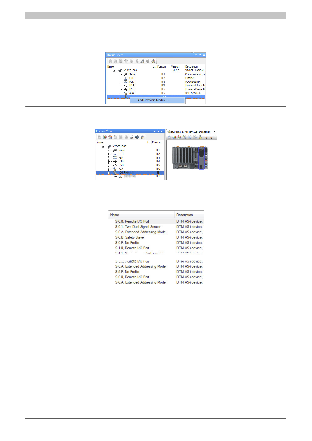
All possible AS-i slave variants have already been imported into Automation Studio as device description files and
can be taken from the Hardware Catalog.
Each AS-i slave is described with its own AS-i profile. The AS-i profile is composed of 4 components:
•I/O configuration
Contains information about the configuration of individual AS-i slave ports: output, input or bidirectional
input/output.
•ID code
Contains the ID code of the slave.
•Extended ID code 1
Length: 4 bits
In extended address mode, the MSB indicates whether it is an A (MSB = 0) or B (MSB = 1) slave (starting
with specification 3.0). In the Automation Studio Hardware Catalog, the extended address mode can be
identified by an "A" in the slave address (e. g."S-0. A"). The lower 3 bits contain additional slave-specific
information.
•Extended ID code 2
Used for slave-specific settings. See description of the corresponding slave.
4 status register bits follow subsequently.
Bit Explanation Values Information
0 Permanent memoryS0 Storage of the address or extended ID code 1
1 Volatile memory
0 No error occurredS1 Peripheral error state occurred
1 Error occurred
S2 Undefined -
0 No error occurredS3 Error occurred while reading a permanent memory area.
1 Error occurred