manuals.online logo
Brands
  1. Home
  2. •
  3. Brands
  4. •
  5. Bang & Olufsen
  6. •
  7. Cassette Player
  8. •
  9. Bang & Olufsen Beocord 4500 User manual

Bang & Olufsen Beocord 4500 User manual

This manual suits for next models

11

Other Bang & Olufsen Cassette Player manuals

Bang & Olufsen Beocord 3300 User manual

Bang & Olufsen

Bang & Olufsen Beocord 3300 User manual

Bang & Olufsen BEOCORD 1500 User manual

Bang & Olufsen

Bang & Olufsen BEOCORD 1500 User manual

Bang & Olufsen Beocord 6500 User instructions

Bang & Olufsen

Bang & Olufsen Beocord 6500 User instructions

Bang & Olufsen Beocord 5000 Type 4715 User manual

Bang & Olufsen

Bang & Olufsen Beocord 5000 Type 4715 User manual

Popular Cassette Player manuals by other brands

Ahuja CPA-360 Operation manual

Ahuja

Ahuja CPA-360 Operation manual

Sony Pressman TCS-60DV Specifications

Sony

Sony Pressman TCS-60DV Specifications

Philips AQ6485/14 Product information

Philips

Philips AQ6485/14 Product information

Sony TCM-200DV - Cassette Recorder operating instructions

Sony

Sony TCM-200DV - Cassette Recorder operating instructions

Nakamichi BX-300 Service manual

Nakamichi

Nakamichi BX-300 Service manual

Panasonic RQ-E25V operating instructions

Panasonic

Panasonic RQ-E25V operating instructions

Aiwa TP-VS535 operating instructions

Aiwa

Aiwa TP-VS535 operating instructions

Yamaha MT8X Operation manual

Yamaha

Yamaha MT8X Operation manual

Sherwood Newcastle D-480 operating instructions

Sherwood

Sherwood Newcastle D-480 operating instructions

Manta MA408 user manual

Manta

Manta MA408 user manual

GPO W0162B user guide

GPO

GPO W0162B user guide

Marantz CP230 Service manual

Marantz

Marantz CP230 Service manual

Sony HST-471 Service manual

Sony

Sony HST-471 Service manual

Sharp JC-AV1 Operation manual

Sharp

Sharp JC-AV1 Operation manual

Pioneer CT-W103 Service manual

Pioneer

Pioneer CT-W103 Service manual

Sony CFS-B15 - Am/fm Stereo Cassette Recorder operating instructions

Sony

Sony CFS-B15 - Am/fm Stereo Cassette Recorder operating instructions

Sony WMFS220 - Portable Sports AM/FM Cassette... operating instructions

Sony

Sony WMFS220 - Portable Sports AM/FM Cassette... operating instructions

Aiwa HS-TA21 operating instructions

Aiwa

Aiwa HS-TA21 operating instructions

manuals.online logo
manuals.online logoBrands
  • About & Mission
  • Contact us
  • Privacy Policy
  • Terms and Conditions

Copyright 2025 Manuals.Online. All Rights Reserved.

Bang
&Olufsen
Beocord
4500
Type
4961,
4962,
4963,
4964,
4965
BEOCORD
3500
Type
4966-4967-4968-4969-4970
SERVICEANVISNING
SERVICE
MANUAL
INDHOLD
CONTENTS
Moduloversigt
.....--.0esceeereee
reer
en
ernst
1
Survey
of
modules
....---..esreeeerrerserrts
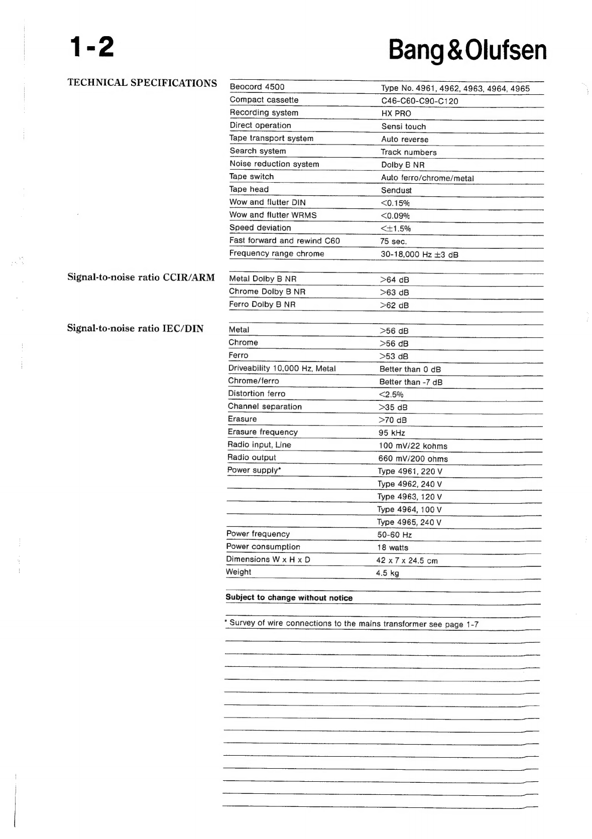
Tekniske
specifikationer
.......+--+sseeersrtrere
1
Technical
specifications
.....------sessersrrr
Diagrammer
......---+eceeececee
reser
ses
erers
see
9
Circuit
diagrams
....-...ceceeseeeesretere
terre
Elektrisk
stykliste
......--....eeeeeeeeee
ernest
3
List
of
electrical
parts
....--+---sserrrererretr
Mekanisk
stykliste
.......---.sseerereeerer
estes
4
List
of
mechanical
parts
....------erssrerreeren
TStEHIAGEP
<caden
ac
eatiee
rind
reise
ncmenneetnes
tee
5
Adjustments
....-.-.-.s-screrererererre
NaslcilelGv
ce
<poctas
taeed
esate
eee
ee
ee
eet
&.
Dictate
qvarncy
ws
teacedecer
Serene:
Reparationstips
........--0sreeserrer
treet
7
Repait
hints
....s0.tsecsaree
ne
ree
eer
eeneenenener
Lsolationstest
sccivetue
ne
tvee<seasees
deseo
oe
8
Insulation
test
.....--..seeeereeeeeece
rete
Bang
&
Olufsen
1-1
Modules
1
CAFS
Control
sass
ei
ceased
ee
Bae
eta
sheeted
diagr.
A,
B,
C
5
2?
Dolby:NR
i:cetic
ss
cchaeaesd
es
Gawd
ees
ca
Oe
Sota
diagr.
B
page
2-4
3
Operation
Panel
.........
0.00
cece
eee
e
eee
een
e
eee
eee
tenes
diagr.
C
page
2-5
4
Tape
Deck
Control
........
0c
cece
cece
eee
eee
eee
eee
eeee
diagr.
D
page
2-6
5
Tape
Head
Rec./P.B.
Switch
.......
0.
cece
ence
eee
eee
eee
eeee
diagr.
A
page
2-3
93)
Tape
Deck
2
iis.
beau
dd
bi
alid
ann
he
cesanacaa
bags
diagr.
A,
B,C,
D
page
2-3,
4,5,
6
1-2
TECHNICAL
SPECIFICATIONS
Signal-to-noise
ratio
CCIR/ARM
Signal-to-noise
ratio
IEC/DIN
Bang
&
Olufsen
Beocord
4500
Type
No.
4961, 4962,
4963,
4964,
4965
Compact
casseite
C46-C60-C90-C120
Recording
system
HX
PRO
Direct
operation
Sensi
touch
Tape
transport
system
Auto
reverse
Search
system
Track
numbers
Noise
reduction
system
Dolby
B
NR
Tape
switch
Auto
ferro/chrome/metal
Tape
head
Sendust
Wow
and
flutter
DIN
<0.15%
Wow
and
flutter
WRMS
<0.09%
Speed
deviation
<1+1.5%
Fast
forward
and
rewind
C60
75
sec.
Frequency
range
chrome
30-18,000
Hz
+3
dB
Metal
Dolby
B
NR
>64
dB
Chrome
Doiby
B
NR
>63
dB
Ferro
Dolby
B
NR
>62
dB
Metal
>56
dB
Chrome
>56
dB
Ferro
>53
dB
Driveability
10,000
Hz,
Metal
Chrome/ferro
Distortion
ferro
Channel
separation
Erasure
Erasure
frequency
Radio
input,
Line
Radio
output
Power
supply*
Better
than
0
dB
Better
than
-7
dB
<2.5%
>35
dB
>70
dB
95
kHz
100
mV/22
kohms
660
mV/200
ohms
Type
4961,
220
V
Type
4962,
240
V
Type
4963,
120
V
Type
4964,
100
V
Type
4965,
240
V
Power
frequency
50-60
Hz
Power
consumption
18
watts
Dimensions
WxHxD
42
x7x
24.5
cm
Weight
4.5
kg
Subject
to
change
without
notice
*
Survey
of
wire
connections
to
the
mains
transformer
see
page
1-7
Bang
&Olufsen
DIAGRAMFORKLARING
Pa
diagrammerne
er
der
angivet
typenumre
pa
tran-
sistorer
og
IC’er.
Hvis
positionsnummeret
er
efter-
fulgt
af
en
stjerne,
skal
reservedelsnummeret
altid
benyttes,
da
denne
komponent
er
specielt
udvalgt,
f.eks.
TR102*.
Komponenttryk
og
koordinatsystem
De
sterste
printplader
er
forsynet
med
kompo-
nenttryk
og
et
koordinatsystem
pa
bade
print-
og
komponentside.
Pa
diagrammerne
er
enhver
komponent
forsynet
med
et
koordinatnummer.
Dette
fortzeller
i
hvilket
koordinat
pa
printpladen,
komponenten
er
placeret.
Koordinatnumrene
er
angivet
med
mindre
skrifttype
end
positionsnumrene.
Styrekredslob
I
visse
styrekredslgb
er
den
aktive
tilstand
angivet
med
en
funktions-
eller
bogstavsangivelse.
Denne
kan
eksempelvis
vere
ST.BY.
=
»low«
i
stand-by-
stilling
eller
ST.BY.
=
»high«
i
stand-by-stilling.
Ledningsforbindelser
Ledningsforbindelserne
pa
diagrammerne
er
samlet
i
»bundter«.
De
enkelte
ledninger
er
forsynet
med
en
af
felgende
koder:
INTERN
FORBINDELSE
PA
EN
DIAGRAMSIDE
Interne
forbindelser
pa
en
diagramside
angives
med
et
tal.
Kneekket
pa
ledningen
viser,
i
hvilken
retning,
den
anden
ende
af
ledningen
findes.
FORBINDELSE
TIL
EN
ANDEN
DIAGRAMSIDE
DIAGRAM
A
|
C3
(32
ee
Forbindelsen
til
en
anden
diagramside
angives
med
et
tal
samt
et
bogstav
for
det
diagram,
forbindelsen
gar
til.
Forsyningsspzendinger
Alle
forsyningsspendinger
i
diagrammerne
er
angivet
med
en
pil
og
en
spendingsangivelse.
Eksempel:
Ved
siden
af
speendingsangivelsen
star
der
f.eks.
7
CON.
Dette
betyder,
at
den
pagaldende
forsy-
ningsspending
gar
til
7
steder
pa
den
pageeldende
diagramside
(7
CON.
=
7
connections).
1-3
EXPLANATION
OF
DIAGRAM
Type
numbers
of
transistors
and
ICs
are
indicated
on
the
diagrams.
If
the
position
number
is
followed
by
an
asterisk
the
spare
part
number
must
always
be
used
because
the
component
in
question
has
been
specially
selected,
e.g.
TR102*.
Component
print
and
coordinate
system
The
largest
PCBs
have
component
prints
and
a
coordinate
system
on
both
the
print
and
the
compo-
nent
side.
On
the
diagrams
every
component
has
a
coordinate
number.
This
indicates
in
which
coordinate
on
the
PCB
the
component
is
situated.
The
coordinate
numbers
are
written
in
smaller
print
types
than
the
position
numbers.
Control
Circuit
In
certain
control
circuits
the
active
mode
is
indi-
cated
by
a
function
term
or
by
an
abbreviation.
This
may
be
e.g.
ST.BY.
=
low
in
the
stand-by
mode
or
ST:BY.
=
high
in
the
stand-by
mode.
Wiring
Connections
The
wiring
connections
on
the
diagrams
are
assembled
in
‘bundles’.
The
individual
wires
are
provided
with
one
of
the
following
codes:
INTERNAL
CONNECTION
ON
ONE
DIAGRAM
PAGE
Internal
connections
on
a
diagram
page
are
indi-
cated
by
a
number.
The
bend
of
the
wire
indicates
in
which
direction
the
other
end
of
the
wire
is
found.
CONNECTION
TO
ANOTHER
DIAGRAM
PAGE
DIAGRAM
C
|
A32
A3
A
connection
to
another
diagram
page
is
indicated
by
a
number
as
well
as
by
a
letter
of
the
diagram
to
which
the
connection
leads.
Supply
Voltages
All
supply
voltages
in
the
diagrams
are
indicated
by
an
arrow
and
a
voltage
indication.
Example:
“7
CON.”
This
means
that
the
supply
voltage
in
question
goes
to
7
different
places
on
the
diagram
page
in
question
(7
CON
=
7
connections).
1-4
STELSYMBOLER
Der
anvendes
3
forskellige
stelsymboler
i
apparatet.
|
=
Stel
j
=
Signalstel
a
=
Chassis
SYMBOL
FOR
SIKKERHEDSKOMPONENTER
ZN
Ved
udskiftning
af
komponenter
med
dette
symbol
skal
der
anvendes
komponenter
med
samme
reser-
vedelsnummer.
Den
nye
komponent
skal
monteres
pa
samme
made
som
den
udskiftede.
MALEBETINGELSER
Alle
DC-spzendinger
er
malt
i
forhold
til
stel
med
et
voltmeter
med
en
indgangsmodstand
pa
10
Mohm.
DC-speendingerne
er
opgivet
i
volt
(V),
f.eks.
0,7
V.
Alle
AC-speendinger
er
malt
i
forhold
til
stel
med
et
voltmeter
med
en
indgangsmodstand
pa
1
Mohm.
AC-speendingerne
er
opgivet
i
millivolt
(mV),
f.eks.
660
mV.
Stilling
gengive
(833
Hz
250
pWb
mm).
Signalvejen
i
optage
position
er
vist
i
venstre
kanal,
og
gengive
position
er
vist
i
hajre
kanal.
Bang
&Olufsen
GROUND
SYMBOLS
Three
different
ground
symbols
are
used
in
the
set.
i
=
ground
s
=
signal
ground
|
=
chassis
SYMBOL
OF
SAFETY
COMPONENTS
LN
When
replacing
components
with
this
symbol,
components
with
identical
part
numbers
must
be
used.
The
new
component
must
be
mounted
in
the
same
way
as
the
one
replaced.
MEASURING
CONDITIONS
All
DC
voltages
have
been
measured
in
relation
to
ground
with
a
voltmeter
with
an
input
resistance
of
10
Mohms.
The
DC
voltages
are
stated
in
volts
(V),
e.g.
0.7
V.
All
AC
voltages
have
been
measured
in
relation
to
ground
with
a
voltmeter
with
an
input
resistance
of
1
Mohm.
AC
voltages
are
stated
in
millivolts
(mV),
e.g.
660
mV.
Position
play
back
(333
Hz
250
pWb
mm).
The
signal
path
in
recording
pos.
is
shown
in
left
channel,
and
replay
pos.
is
shown
in
right
channel.
ERLAUTERUNGEN
ZUM
SCHALTBILD
Auf
den
Schaltbildern
sind
Typen-Nummern
fiir
Transistoren
und
IC’s
angegeben.
Wenn
auf
die
Positionsnummer
ein
Stern
folgt,
ist
die
Ersatzteilnummer
zu
benutzen,
da
diese
Kompo-
nente
speziell
ausgewdhlt
worden
ist
—
z.B.
TR102*.
Komponentendruck
und
Koordinatensystem
Die
gré&ten
Printplatten
sind
mit
Komponenten-
druck
und
Koordinatensystem
sowohl
auf
der
Print-
als
auf
der
Komponentenseite
(Bestiickungsseite)
versehen.
In
den
Schaltbildern
ist
jede
Komponente
mit
einer
Koordinatennummer
versehen.
Diese
gibt
an,
in
welcher
Koordinate
auf
der
Printplatte
die
Kompo-
nente
angebracht
ist.
Die
Koordinatennummer
ist
in
kleinerer
Schrift
als
die
der
Positionsnummer
ange-
geben.
NOTICE
EXPLICATIVE
DES
SCHEMAS
Sur
les
schémas,
les
numéros
de
types
sont
indi-
quées
pour
les
transistors
et
les
circuits
imprimés.
Si
le
numéro
de
position
est
suivi
par
un
astérisque,
il
est
impératif
d’utiliser
le
numéro
de
la
piéce
de
rechange,
étant
donné
qu'il
s’agit
d’un
composant
spécialement
sélectionné,
par
exemple
TR102*.
Composants
imprimés
et
systeme
de
coordonnées
Les
circuits
imprimés
les
plus
grands
sont
munis
de
composants
imprimés
et
de
systémes
de
coordon-
nées
sur
la
cété
impression
et
sur
la
cété
compo-
sant.
Chaque
composant
figurant
sur
un
schéma
est
pourvu
d’un
numéro
de
coordonnées.
Ceci
indique
dans
quelles
coordonnées
de
la
carte
le
component
en
question
est
situé.
Les
numéros
de
coordonnées
sont
écrits
avec
des
caractéres
plus
petites
que
celles
des
numéros
de
position.
Bang
&
Olufsen
1-5
Steuerschaltkreise
Circuits
de
commande
Bei
gewissen
Steuerschaltkreisen
ist
der
aktive
Dans
certains
circuits
de
commande,
l’état
actif
est
Zustand
durch
eine
Anzeige
der
Funktion
oder
eine
indiqué
par
un
terme
de
fonction
ou
par
une
repré-
Buchstabenbezeichnung
angegeben,
z.B.
ST.BY.
=
sentation
en
lettres.
Celle-ci
peut
étre
p.ex.
ST.BY.
=
»low”
in
der
Bereitsschaftsstellung
oder
ST.BY.
=
bas
en
position
veille
ou
ST.BY.
=
haut
en
position
»high”
in
der
Bereitsschaftsstellung.
veille.
Leitungsverbindungen
Connexions
des
fils
Die
Leitungsverbindungen
sind
auf
den
Schaltbil-
Les
connexions
de
fils
sur
les
schémas
sont
assem-
dern
in
,,Biindeln”
zusammengefaft.
Die
einzelnen
blées
en
«faisceaux».
Chaque
fil
est
pourvu
d’un
des
Leitungen
sind
mit
einer
der
folgenden
Code-
codes
suivants:
Bezeichnungen
versehen:
INTERNE
VERBINDUNGEN
AUF
EINER
SCHALT-
CONNEXION
INTERNE
SUR
UN
COTE
DU
BILDSEITE
SCHEMA
t
t
bh
¢
Interne
Verbindungen
auf
einer
Schaltbildseite
Connexions
internes
sur
une
page
de
schéma
sont
werden
mit
einer
Nummer
angegeben.
Die
Biegung
indiquées
par
un
chiffre.
Vangle
du
fil
indique
la
der
Leitung
zeigt,
in
welcher
Richtung
das
andere
direction
dans
laquelle
l’autre
bout
du
fil
peut
étre
Ende
der
Leitung
sich
befindet.
trouvé.
VERBINDUNGEN
AN
EINE
ANDERE
SCHALT-
CONNEXION
VERS
UN
AUTRE
COTE
DU
BILDSEITE
SCHEMA
SCHALTBILD
A
SCHALTBILD
C
DIAGRAM
A
DIAGRAM
C
|
|
|
3
C32
A32
A3
Na
re
ie
Eine
Verbindung
an
eine
andere
Schaltbildseite
wird
|
Une
connexion
vers
une
autre
page
de
schéma
est
mit
einer
Nummer
sowie
einem
Buchstaben
des
indiquée
par
un
chiffre
et
par
une
lettre
indiquant
le
Schaltbildes,
an
das
die
Verbindung
geht,
angegeben.
schéma
que
la
connexion
relie.
Versorgungsspannungen
Tensions
d’alimentation
Alle
Versorgungsspannungen
in
den
Schaltbildern
Sur
les
schémas
tous
les
tensions
d’alimentation
werden
mit
einem
Pfeil
sowie
einer
Indikation
der
sont
munies
d’une
fléche
et
d’une
indication
du
Spannung
angegeben.
voltage.
Beispiel:
Exemple:
Neben
der
Netzspannung
steht
z.B.
7
CON.
Dies
A
cété
de
lindication
du
voltage
est
indiqué
p.
ex.
bedeutet,
da
die
Versorgung
an
7
Stellen
auf
das
«7
CON».
Cela
signifie
que
la
tension
d’alimentation
Schaltbild
geleitet
wird
(7
CON.=
7
connections).
en
question
est
conduite
a
7
endroits
sur
le
schéma
(7
CON.
=
7
connections).
MASSE-SYMBOLE
SYMBOLES
CONCERNANT
LA
MASSE
Im
Geradt
werden
3
verschiedene
Masse-Symbole
On
utilise
trois
signes
différents
pour
indiquer
la
verwandt.
masse
dans
|’appareil.
1g
=
Masse
He
=
Masse
,
=
Signal-Masse
l
=
Potentiel
de
masse
du
signal.
ih
=
Chassis-Masse
ale
=
Chassis
1-6
SYMBOL
FUR
SICHERHEITSKOMPONENTEN
LN
Bei
der
Auswechslung
von
Komponenten
mit
diesem
Symbol
sind
Komponenten
mit der
gleichen
Ersatznummer
zu
verwenden.
Die
neue
Komponente
ist
in
derselben
Weise
wie
die
ausgewechselte
Komponente
zu
montieren.
MESBEDINGUNGEN
Alle
DC-Spannungen
sind
im
Verhaltnis
zu
Masse
mit
einem
Voltmeter
mit
einem
Eingangswiderstand
von
10
Mohm
gemessen.
Die
DC-Spannungen
sind
in
Volt
(V)
aufgegeben,
z.B.
0,7
V.
Alle
AC-Spannungen
sind
im
Verhiltnis
zu
Masse
mit
einem
Voltmeter
mit
einem
Eingangswiderstand
von
1
Mohm
gemessen.
Die
AC-Spannungen
sind
in
Millivolt
(mV)
aufge-
geben,
z.B.
660
mV.
Position
Wiedergabe
(333
Hz
250
pWb
mm).
Der
Signalweg
in
Aufnahmeposition
ist
im
linkem
Kanal
gezeigt,
und
die
Wiedergabeposition
ist
im
rechten
Kanal
gezeigt.
Explanation
of
the
fuse
symbols
used
in
the
set
Explanation
de
symboles
du
fusible
utilisés
dans
lappareil
Bang
&
Olufsen
SYMBOLE
DES
COMPOSANTS
SECURITE
AN
En
remplacant
un
composant
portant
ce
symbole
il
faut
utiliser
les
composants
du
méme
numéro
de
référence.
Le
nouveau
composant
doit étre
monté
de
la
méme
maniére
que
celui
qu'il
remplace.
CONDITIONS
DE
MESURE
Toutes
les
tensions
en
courant
alternatif
(CA)
sont
mesurées
par
rapport
a
la
masse
a
l’aide
d’un
volt-
métre
avec
une
résistance
interne
de
10
Mohms.
Les
tensions
CC
sont
indiquées
en
volt
(V),
par
exemple
0,7
V.
Tous
les
tensions
en
courant
alternatif
(CA)
sont
mesurées
par
rapport
a
la
masse
4a
l’aide
d’un
volt-
métre
avec
une
résistance
interne
de
1
Mohm.
Les
tensions
CA
sont
indiquées
en
millivolt
(mV),
par
exemple
660
mV.
Position
reproduction
(333
Hz
250
pWb
mm).
La
trajectoire
du
signal
en
position
enregistrement
est
indiquée
dans
le
canal
gauche,
et
en
position
reproduction
dans
le
canal
droit.
Replace
with
the
same
type
of
315
milliamperes
250
volts
slow
acting
fuse.
[
[7315
ma
LT
250v
“Vj
amperes
250
volts.
Remplacer
par
un
fusible
retardé
de
la
méme
type
et
de
315
milli-
Bang
&
Olufsen
1-7
Oversigt
over
ledningsforbindelser
Survey
of
wire
connection
to
the
mains
til
nettransformatoren
transformer
fewest
1
[ef]
eis
mao
moved
worse]
| |
[ew
mar
ooo
240
V,
GB/AUS
sorssi0.,
=
||
[za
|76]
[73]
|
[200
ma-T
6600089
sono
[raf]
|
[rr]
[ois
mart
ooo
ons)
|
[rele]
[ra]
|
fone
ma
amos
*Special
transformer
2-1
CONTROL
P14.8V
Vy
22_|27/28/291
30
[32/33/34
35/36
ws
TAKE
UP
24]
POWER
Bo
we
RESET
&
TAPE
LEADER
TTR
6-17
Ss]
INFORMATION
=x]
SILENCE
39
ENABLE
Ai
PAR-SER
TAPE
DECK
DATA
Bang
&
Olufsen
TAPE
DECK
FEEDBACK’
931C
12
TAKE
UP
LIR
93811314
POSITION
SWITCH
TAPE
DECK
CONTROL
4IR4I6
TAPE
HEAD
LID
CONTROL
93M1
4TRE
4103