1640-IN-026-A-00 Page 2 of 10
1.0 INTRODUCTION
The Society of the Plastic Industry, Inc. has established a
standard communication protocol (SPI) that provides a plat-
form for instrumentation manufactured by different compa-
niestocommunicatetogetheronthesameRS-485localarea
network.
TheSPIAuxiliaryEquipmentInterfacemodule(71-946-X)will
allow the MACO®4000, 5000 and 6000 Series controllers to
communicate (via SPI protocol) with auxiliary equipment
typically found in plastic molding, extruding or blowmolding
facilities, including mold temperature controllers, hot runner
controllers,chillers,dryers, additive feeders andmeltpumps.
A maximum of 32 separate devices can be connected to a
MACO on the same SPI auxiliary interface module. With this
interfacethestandardfeaturesoftheMACOcontrollerswould
beutilized, such as recipestorage (allowing fast setup times)
RLDinterface capabilitywithouttheneedfor extensivewiring
to the Sequence inputs/outputs Statistical Process Control
(SPC) of auxiliary equipment parameters.
The SPI Auxiliary Equipment Interface module is pre-config-
ured to communicate with SPI compatible auxiliary equip-
ment. The end user or OEM needs no programming skill, or
knowledge of the intricacies of the SPI protocol. You simply
need to know what SPI compatible devices being used and
the quantity you wish to communicate with. The user needs
a working knowledge of Barber-Colman OptiGrafix and RLD
programming software.
The SPI Auxiliary module will communicate with any device
listed in the current, released version 3.01a of the SPI Phase
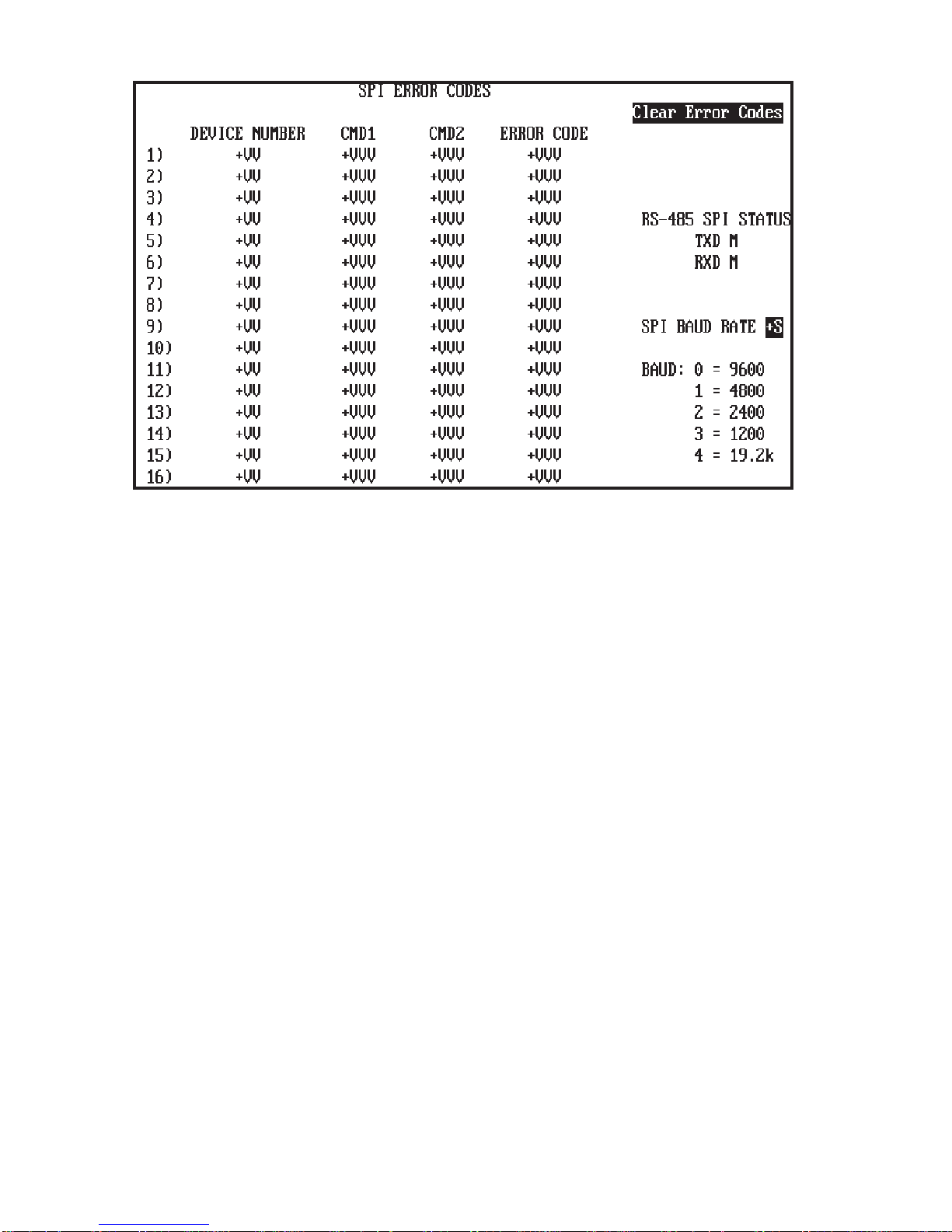
I protocol (also listed in section 3.1 of this document). It will
communicate at a user selectable baud rate of 1200, 2400,
4800, 9600, and 19.2K. Every "required" command, as de-
fined by the protocol, for the devices listed are supported in
this release of firmware.
2.0 SETUP INSTRUCTIONS
2.1 Board Location
TheSPIAuxiliarymodulemaybeplacedinslot1,2,or3ofthe
communicationsmotherboard(A-13408-1).Thecommunica-
tions motherboard must be installed in primary chassis 1 in a
slotwhichhasacontroldatabusconnector;thisisthemiddle
connector on the back-plane of the MACO controllers. You
may only have one (1) RS-485 SPI Module per system.
The SPI Auxiliary Equipment module can be used with data
handler version V20.75 or newer.
2.2 Jumpers and Switches
There are two hardware jumpers that have to be manual set
before installing the SPI Auxiliary module (daughterboard)
onto the communications motherboard A-13408-1XX.
Jumpers J1 and J2 are to be in the "IN" position, see Figure
2.2. These jumpers connect the bus termination resistors to
the Data(+) and Data(-) terminals.
SHIELD
ISOCOM
DATA
DATA
4
3
2
1
ON OFF
S1
8
7
6
5
4
3
2
1
IN OUT
J1
U10
A-13404-2
RS-485 COMMUNICATIONS
T1
IN OUT
J2
Figure 2.2 SPI Auxiliary Interface module.
2.3 Node Address
ThenodeaddressswitchS1ontheSPIAuxiliarymoduleisnot
used.
2.4 MACO SERIAL COMMUNICATION SETUP
TheMACOserialcommunicationssetupscreen(figure2.4)is
used for setting baud rates and enabling communications.
This controller can have as many as three separate external
devices connected for use with serial communications.
Daughterboards purchased for the communications
motherboard determine what type of device can be con-
nected. The COMM setpoints correspond to daughterboard
locations on the motherboard:
COMM 1 bottom slot.
COMM 2 middle slot.
COMM 3 upper slot.
2.4.1 Modfiles and Sample Screens
The diskette SA-00064-01X-0-00 is provided. It contains the
modfiles and sample SPI screens that will be required by the
MACO and OptiGrafix programming software. Preform the
followingstepstoinstallthesefilesontoyouruserapplication.
A. Copy the two modfiles; to copy the modfiles place
the diskette into floppy drive and copy to your exist-
ing modfile directory.
Example: Copy A:\modfiles\*.* C:\modfiles.
B. Using the OptiGrafix screen editor copy the SPI
samplescreensfromthediskette(A:\ADB0001name
of application to copy from) to your user application
on the hard drive using the Application ...
Utilities...Copy from ... Screens Feature.
2.4.2 COMM Setpoints
Examine the Module Information Screen to determine which
communicationsboardsarepresentandthenenterasetpoint
foreachdaughterboard,seeFigure2.4.COMM1,2or3may
be an RS-485 device (a setpoint of 0 to enable SPI commu-
nications) and COMM 1, 2 or 3 may be an RS-232 device (a
setpoint of 0, 1 or 2). Note that only one of EACH DEVICE is
allowed (i.e., can’t have two RS-232 printers or two RS-232
PCs, etc.). Al other information on this screen (Figure 2.4) is
for RS-232 communications.