Barco NGS-V161 User manual

NGS-V161
Installation manual
R59112800-00

2
Intentionally left blank

Customer notice 3
1Customernotice
Thank you for buying Barco!
Barco is a world leader in display and visualization solutions. We are convinced that you will
enjoy our products.

4About
2 About
2.1 NGS-V161
The NGS-V161 network video recorder supports 16 channels of NTSC or PAL video via an
onboard dedicated H.264 encoder. Each channel is capable of compressing a single full D1
video stream and a G.711 audio stream in real time.
The NGS-V161 provides 16 channel video encoding and network transmission at up to full
D1 resolution. The network video platform utilizes the latest H.264 standard to ensure the
highest level of video quality with the lowest levels of storage and network bandwidth
requirements. Supporting full D1 NTSC and PAL formats, our network video platforms take
16 analog video signals and simultaneously encode them to H.264 compressed digital
format, allowing customers to build world class network video solutions with excellent
video quality.
Features
• 16-channel full D1 video encode
• H.264 AVC hardware encode
• Supports NTSC and PAL video input
• 16-channel audio encode up to 16 bit – 32 kHz
• Intel Q35 + ICH9DO
• Intel Core 2 Duo processor
• DDR2 memory
• Dual gigabit Ethernet
• Scalable Video Coding (SVC)
2.2 Content Quick Start Guide
This installation manual is designed to aid quick installation and set up of your new NGS-
V161, however, should you experience any problems not covered in this guide please refer
to the User Manual.
The installation manual consists of the following steps:
STEP1: Checking package content
The chapter gives an overview of all parts delivered within the package of the unit and
some unpacking warnings.
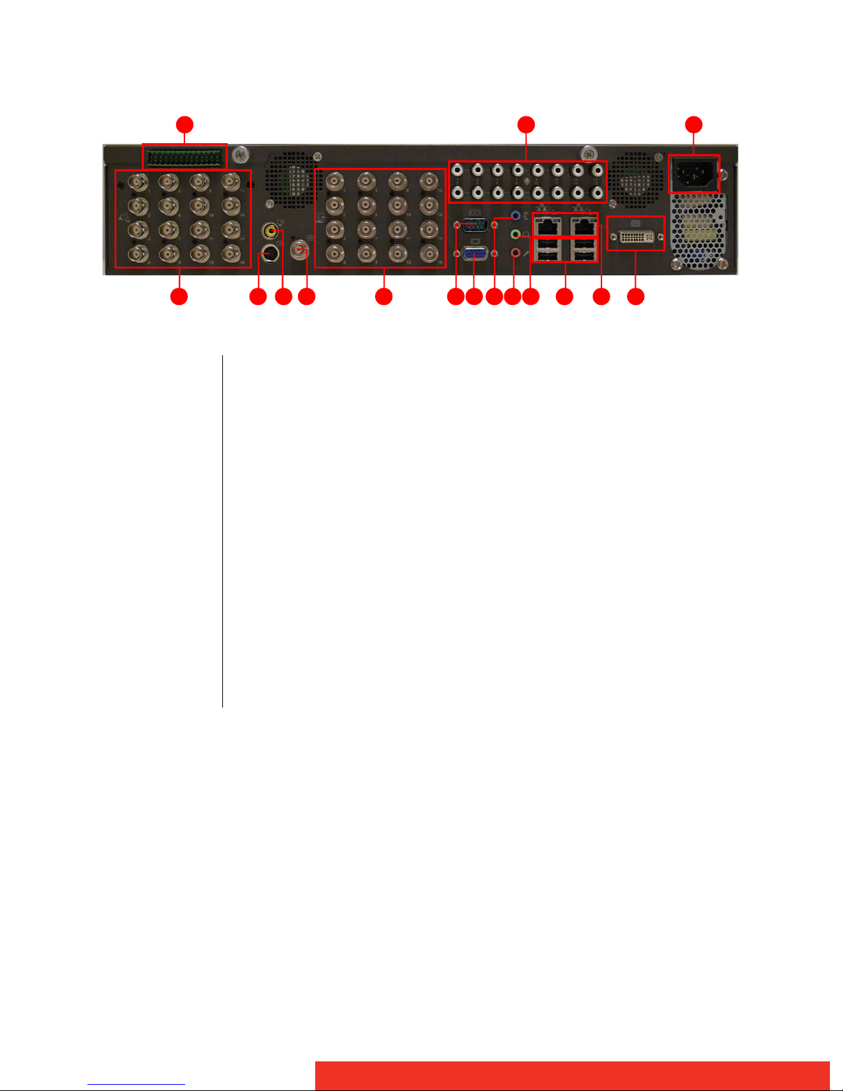
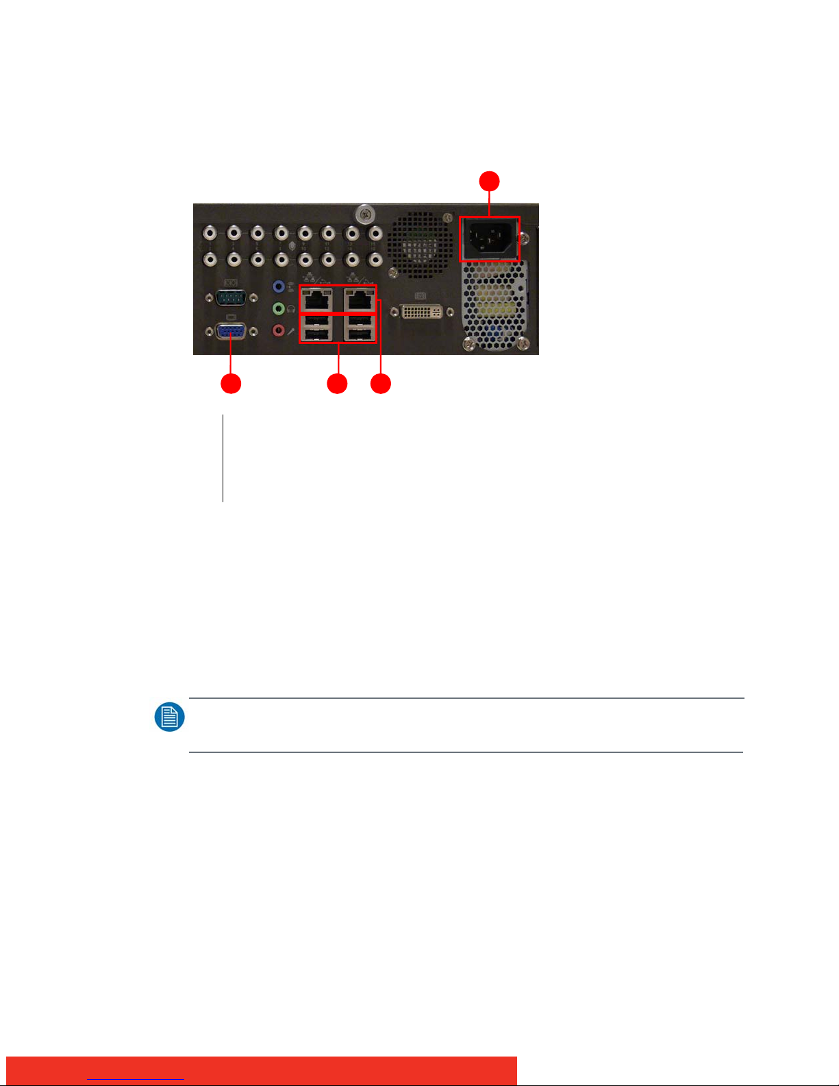
STEP2: Device and its components
The chapter gives overviews of the device and the location of the components on it.
STEP3: Connecting the components
This chapter describes how the system components should be connected.
STEP4: Switching on the system
This chapter describes the setup procedure to follow when you switch on the system for the
first time.
STEP5: Controlling streams
This chapter contains how you can control streams over the network.

About 5
2.3 Notation convention
Following notations are applicable to this manual and should be respected throughout the
manual.
WARNING:
Warnings – presented in this manual, provide information, which if not adhered to, may result in personal
injury or death.
CAUTION:
Cautions – presented in this manual, provide information, which if not adhered to, may result in damage to the
equipment.
NOTE:
Notes – presented in this manual, provide information, which emphasize points, significant to understand and
operate the unit.
IMPORTANT:
Important – presented in this manual, provide information, which is important to highlight.
2.4 Change record
Revision Date Description
00 Sept 2011 Initial Release

6STEP1: Checking package content
3 STEP1: Checking package content
3.1 Package content
Your box should contain:
• NGS-V161 (B560686)
• MGS software CDROM (R33044100)
• Installation Manual (R59112800)
3.2 Packaging
A safe transport of the units can only be guaranteed if the original undamaged package is
used for shipping. Handle with care when transporting.
Keep your original packaging. It is designed for this unit and is the ideal protection during
transportation.

STEP2: The device and its components 7
4 STEP2: The device and its components
4.1 Front View NGS-V161
Figure 1: Front view
1DVD-RW drive
22 x USB ports
3Status LEDs (L1, L2, L3, L4)
4Reset button
5Power Switch
L1
L2
L3
L4
Ethernet Port 1 Led
Ethernet Port 2 Led
Hard Disk Led
Power Led
Green
Orange (flashing)
Green
Orange (flashing)
Green
Red
When LAN is connected
When Data is being accessed
When LAN is connected
When Data is being accessed
When system is powered on
When Hard Disk is being accessed
1
4 52 3
L1 L3
L2 L4
4 52 3

8STEP2: The device and its components
4.2 Rear view NGS-V161
Figure 2: Rear view
1Video Looping
2TV-Out via RCA
3S-Video
4Sequence Monitor
5Video Input
6COM Port
7VGA Connector
8Line In (for audio sources)
9Microphone Port
10 Line Out Port (headphone, speaker)
11 4 USB Ports
12 2 Ethernet Ports
13 DVI-D Port
14 Power
15 Audio Input
16 Alarm
14
15
16
1 6 83 5 12 132 4 7 9 10 11

STEP3: Connecting the components 9
5 STEP3: Connecting the components
5.1 Cabling and connections
Figure 3: Connections at rear side
Make the following connections
1. Connect a control screen to the VGA output connector (see 1 on the figure above)
2. Connect the USB Keyboard and Mouse into vacant USB connectors (see 2 on the figure above).
3. Connect your network to Ethernet port 1 (see 3 on the figure above)
4. Connect the power cable (see 4 on the figure above)
NOTE:
The keyboard and mouse can also be plugged into USB connectors on the front side of the unit.
1VGA output connection for control screen
24 USB ports (keyboard and mouse)
32 Ethernet ports (port 1: left, port 2: right) for network connection
4Power connection
4
3
12

10 STEP4: Switching on the system and Setup
6 STEP4: Switching on the system and Setup
6.1 Switching On and Setup
Figure 4: Power On the unit
1 Power On the unit by pressing the Power Switch (see 1 on the figure below).
2. Insert the MGS software CDROM (R33044100) in the CDROM drive (see 1 on the figure below)
as soon as the unit is powered on.
3The Setup procedure starts automatically and takes approximately 15 minutes.
When the setup is finished, the CDROM drive opens and the system reboots auto-
matically.
1Power Switch
2CDROM drive
2
1

STEP5: Using the NGS web interface 11
7 STEP5: Using the NGS web interface
7.1 Pre-configured network settings
After the installation of the MGS software, the unit is pre-configured with a default IP
address.
The default network settings are as follows:
7.2 Starting the web interface
The web interface provides access to configuration and operating parameters of the NGS-
V161.
The web interface runs in a standard web browser. It can be accessed from any PC within
video network.
To start the web interface:
• On the computer open a web-browser.
• Enter the IP address of the NGS-V161 into the address bar of the browser. If it had not
been configured yet, the streaming network interface of the unit has the default factory
IP address https://172.16.0.2. The browser will display the web interface.
NOTE:
Accept the certificate before the web browser opens.
When the web interface has started, its home page can be seen. On the left hand side there
is a navigation-menu, which provides access to the different kind of settings. Each section
can be accessed on an individual page.
The web interface can be used in three different modes: standard user mode (without
login), Barco mode and administration mode. Depending on this mode the menu as well as
the possibility to configure settings on the respective pages differs. The mode can be
switched by logging in or out.
IP address 172.16.0.2
Net mask 255.248.0.0
Default gateway 172.16.0.1
DHCP Disabled

12 STEP5: Using the NGS web interface
Figure 5: Left: Standard mode & Barco mode, Right: Administrator mode
NOTE:
It is not possible to change the Functional settings in the standard user mode. To change these settings login
to Barco mode or administrator mode.
7.3 Changing the IP address via the web interface
• To change the IP address, you first need to be logged in as administrator:
3Use the link “Log in” at the right top corner of the screen.
3A login and password will be needed here:
Login=admin, Password:b4rc0,BCD
•Nowgoto
System settings, Network configuration
and the following window appears
on the screen:

STEP5: Using the NGS web interface 13
Figure 6: Network configuration – using DHCP
• When DHCP is selected, an IP address will be automatically allocated to the unit.
• When Static is selected, one can manually change the IP address as shown in the
screenshot below. After the IP address is changed, click the Update button on the right
hand side.

14 STEP5: Using the NGS web interface
Figure 7: Network configuration – using Static
• After changing the network configuration, one should restart the services:
3Go to
System settings, System access
and select Restart Service(s).
3Push the update button.
3Select
Yes
to confirm.

STEP5: Using the NGS web interface 15
7.4 Showing the workers via the web interface
•Goto
Functional settings, workers
and the following window appears on the screen:
Figure 8: List of workers
NOTE:
The workers are listed from 100 to 115. Worker 100 matches input 1, worker 115 matches input 16.

16 STEP6: Video streaming over the network
8 STEP6: Video streaming over the network
8.1 Connecting the video input(s)
The video signal must be provided on a BNC cable. Connect the source to one of the 16 BNC
connectors on the unit.
Figure 9: Connecting the video input(s)
IMPORTANT:
Make sure that all inputs that are connected to the unit have the same format.
8.2 Checking the video input(s) via RTSP
One can check the video input(s) via RTSP:
NOTE:
VideoLan Client (VLC
www.videolan.org
) media player is used in this example but any other media player
that allows network streaming can be used.
• Open the media player.
•Goto
Media, Open Network Stream
.
116 Video inputs
1

STEP6: Video streaming over the network 17
Figure 10: Open Network Stream (VLC media player)
• Give in the URL to connect to the unit. If it had not been configured yet, the streaming
network interface of the unit has the default factory IP address
rtsp://172.16.0.2
fol-
lowed by the worker (worker100 to worker115).

18 STEP6: Video streaming over the network
Figure 11: Enter the network URL
NOTE:
In the example above, worker100 is selected. One can do this for every worker.
•Pushthe
Play
button. The video stream should be visible.

Further reference 19
9 Further reference
To gain full advantage of your new NGS-V161 system it is recommended that you study the
User Manual that can be found on the CDROM.

20 Further reference
Table of contents
1 Customer notice ........................................................................................................................... 3
2 About ............................................................................................................................................ 4
2.1 NGS-V161 ...................................................................................................................................... 4
2.2 Content Quick Start Guide............................................................................................................. 4
2.3 Notation convention ..................................................................................................................... 5
2.4 Change record ............................................................................................................................... 5
3 STEP1: Checking package content ............................................................................................... 6
3.1 Package content ........................................................................................................................... 6
3.2 Packaging ...................................................................................................................................... 6
4 STEP2: The device and its components....................................................................................... 7
4.1 Front View NGS-V161 ................................................................................................................... 7
4.2 Rear view NGS-V161..................................................................................................................... 8
5 STEP3: Connecting the components ............................................................................................ 9
5.1 Cabling and connections............................................................................................................... 9
6 STEP4: Switching on the system and Setup.............................................................................. 10
6.1 Switching On and Setup ............................................................................................................. 10
7 STEP5: Using the MGS web interface ........................................................................................ 11
7.1 Pre-configured network settings ............................................................................................... 11
7.2 Starting the web interface ......................................................................................................... 11
7.3 Changing the IP address via the web interface ........................................................................ 12
7.4 Showing the workers via the web interface............................................................................. 15
8 STEP6: Video streaming over the network ............................................................................... 16
8.1 Connecting the video input(s) ................................................................................................... 16
8.2 Checking the video input(s) via RTSP ........................................................................................ 16
9 Further reference ....................................................................................................................... 19
Table of contents
Popular Network Hardware manuals by other brands

ZyXEL Communications
ZyXEL Communications Prestige 2602HW Series user guide

HPE
HPE Synergy 12Gb SAS Storage user guide

Nokia
Nokia XS-2426G-B Product guide

Matrix Switch Corporation
Matrix Switch Corporation MSC-CP8X1E product manual

Crestron
Crestron QM-WMIC Operation and installation guide

Lantronix
Lantronix XPort user guide