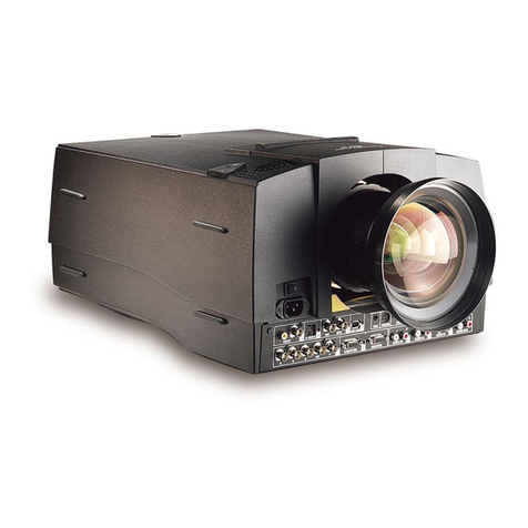
Barco BarcoData 2100 LC User manual

BARCO PROJECTION SYSTEMS
Rev 00
RETRO BLOCK DATA
INSTALLATION MANUAL
Date : 200598
2100LC
R9001168
Art. No : R5975349A

BARCO nv/Projection Systems
Noordlaan 5
B-8520 Kuurne
Belgium
Tel : +32/56/368211
Fax : +32/56/351651
Visit Barco at the web : http://www.barco.com
Printed in Belgium
FEDERAL COMMUNICATION COMMISSION (FCC STATEMENT)
This equipment has been tested and found to comply with the limits of a class A digital device, pursuant to Part 15 of the FCC Rules. These
limits are designed to provide reasonable protection against harmful interference when the equipment is operated in a commercial environment.
This equipment generates, uses and can radiate radio frequency energy and, if not installed and used in accordance with the instruction
manual, may cause harmful interference to radio communications. Operation of this equipment in a residential area is likely to cause harmful
interference in which case the user will be required to correct the interference at his own expense.
Note :
The use of shielded cables is required to comply within the limits of Part 15 of FCC rules and EN55022.
* All the safety and operating instructions should be read before using this unit.
* The safety and operating instructions manual should be retained for future reference.
* All warnings on the equipment and in the documentation manuals should be adhered to.
* All instructions for operating and use of this equipment must be followed precisely.
Due to constant research, the information in this manual is subject to change without notice.
Produced by BARCO NV, May 1998.
All rights reserved.
Trademarks are the rights of their respective owners.

i-1
Table of Contents
5975349A RETRO BLOCK DATA 2100LC 200598
iTABLE OF CONTENTS
TABLE OF CONTENTS ......................................................................................................................................................... I-1
POWER CONNECTION ...................................................................................................................................................... 1-1
Power (mains) cord connection ......................................................................................................................................................... 1-1
Fuses .................................................................................................................................................................................................. 1-1
Switching on ....................................................................................................................................................................................... 1-1
Lamp lifetime ....................................................................................................................................................................................... 1-2
Switching to stand-by. ........................................................................................................................................................................ 1-2
Switching off ...................................................................................................................................................................................... 1-2
PASSWORD SET UP ........................................................................................................................................................... 2-1
How to Enable or Disable the Password ........................................................................................................................................... 2-1
How to Change the Password Menu ................................................................................................................................................. 2-2
OFF-AXIS PROJECTION ..................................................................................................................................................... 3-1
Off-axis projection .............................................................................................................................................................................. 3-1
Adjustment Procedure ........................................................................................................................................................................ 3-1

1-1
Power Connection
5975349A RETRO BLOCK DATA 2100LC 2005984
1
Stand by button
(17(5
3$86(
3+$6(
)5( (=
7( ;7
(;,7$'-
$''5
67%<
6+$531(66
7,17
&2/25
%5,*+71 (66
&2175$67
087(
%$/$1&(
75(%/(
92/80(
%$66
+(/3
"
&2/25
3+$6(
6+$531 7,17 %5,*+71
67$1'%<
(17(5
7(;7
(;,7
3$86(
&2175$67
POWER CONNECTION
Fuses
Warning
For continued protection against fire hazard :
- replace with the same type of fuse.
- refer replacement to qualified service personnel
Fuse type : T16 AH/250V Order no. : B370076
Switching on
Use the power switch to switch on.
When '0' is visible, the projector is switched off.
When '1' is visible, the projector is switched on.
When switching on with the power switch, the projector starts in the
stand by mode.
To start image projection, press the 'Stand by' button on the local key-
pad or on the remote control.
Power (mains) cord connection
Use the delivered power cord to connect your projector to the wall
outlet. Plug the female power connector into the male connector at
the front of the projector.
The power voltage for the projector is indicated on the identification
plate on the rear of the projector.
The projector input voltage is fixed on 120 Vac.
This projector may be connected to an IT-power system.
$8',2,1&
$8',2,1%
$8',2,1$
9,'(2
9,'( 2
69, '(2
5*%+&9
5*%+&9
/5 /5 /5 /5
,5
5 5
**
%%
+& +&
9
9
3257
3257
3257
32573257
5628756,1
&2003257
&75/
KDUGZLUHUHPRWH
2KP:
/5
72/2&$/&21752/21/<
$8',2287
$8',2
,1
&
$8',2
,1
%
$8',2
,1
$
/5 /5 /5 /5
$8',2
287

1-2
Power Connection
5975349A RETRO BLOCK DATA 2100LC 200598
Switching to stand-by.
When the projector is running and you want to go to stand-by, press
the stand-by key.
Caution : Before powering down the projector, switch the projector
to stand-by and let the projector lamp cool down until the fans stop
blowing (or for at least 15 minutes).
Switching off
To switch off:
- Press first STANDBY key and let cool down until the fans stop
blowing (or at least 15 minutes).
- Switch off the projector with the power switch.
Lamp lifetime
30 hours before end of lamp lifetime, the following message will
scrolling over the screen for 1 minute. This message will be repeated
every 30 minutes. Press EXIT to remove the message before the
minute is over.
When the end of lamp lifetime is reached, the following message, with
the exact run time is displayed on the screen.
Lamp run time is 1000 hours. Operating the lamp longer than 1000
hours may damage the projector. Please replace the lamp.
When OK (ENTER) is pressed to go on, the warning will be repeated
every 30 minutes.
The total lifetime of the lamp for a safe operation is depending on the
type of lamp and on the operating mode. The different values are
shown in Table 1.
Do not use it longer. Always replace with a same type of lamp. Call
a BARCO authorized service technician for lamp replacement.
Warning : Using a lamp longer than Lamp Lifetime
is dangerous, the lamp could explode.
Note: Switching the projector off and on again, adds
a penalty time of 45 minutes to the lamp run time.
Remaining lamp
run time: 20
hours
Table 1
$UWLFOH
1XPEUH 'LPPLQJ/DPS
'ULYH0RGH /DPS
/LIHWLPH
5 'LPPLQJ
5 (FRQRPLF
1RUPDO
5 'LPPLQJ

2-1
Password Set Up
5975349A RETRO BLOCK DATA 2100LC 200598
2PASSWORD SET UP
How to Enable or Disable the Password
The password function is enabled/disabled when the password
strap plug on the controller circuit board module is installed in the
specified way. To get access to the controller circuit board module,
proceed as follows:
Remove top cover of projector as described in point of the
'voltage adaptation procedure' in Chapter 1 'Power Connection'.
The password strap on the controller circuit board module will
now be visible.
The strap plug can be seen approximately half way down on the
left side of the circuit board. To change its position just unplug by
pulling it out of its pins. The choice of password function is a user
definable decision!
a. When the password strap is inserted into the right pin and the
middle pin the password function is enabled.
b. When the password strap plug is inserted into the left pin and
the middle pin the password function is disabled.
PASSWORD
STRAP
PLUG
CONTROLLER
CIRCUIT
BOARD
MODULE
Once the password strap plug position has been chosen it is
necessary to secure the projector. Follow the instructions in reverse
order to reassemble the projector.
PASSWORD
STRAP PLUG
- ENABLE
PASSWORD
STRAP PLUG
- DISABLE
a. b.

2-2
Password Set Up
5975349A RETRO BLOCK DATA 2100LC 200598
SERVICE
IDENTIFICATION
CHANGE PASSWORD
CHANGE LANGUAGE
CHANGE PROJ. ADDRESS
CHANGE BAUDRATE PC
RESET LAMP RUN TIME
LAMP RUN TIME HISTORY
LAMP DRIVE MODE
CHANGE PASSWORD
ENTER NEW PASSWORD
0000
SELECT WITH çOR é
THEN <ENTER>
<EXIT> TO RETURN
How to Change the Password Menu
First enter into the Service mode (refer to the Owners manual Chapter
10 for exact procedural steps.)
Then highlight Change password by pressing the control disc up or
down.
ENTER displays the Change Password menu.
EXIT returns to the adjustment selection menu.
The old password is displayed and can be changed by entering the
digits with the numeric keys of the RCU or local key-pad.
Press ENTER to save the new entered password.
Press EXIT if no changes have to be made.

3-1
Off-axis Projection
5975349A RETRO BLOCK DATA 2100LC 200598
3OFF-AXIS PROJECTION
Off-axis projection
The projector can be adapted to off-axis installation in order to meet
environmental conditions. The range within which the projection
angle can be changed is 0° (= on-axis) to 10° downwards for the
QSD(0.8:1) and QSD(1.2:1) lens.
For every possible installation a number of things have to be geared
for one another:
- chosen lens : QSD(0.8:1) or QSD(1.2:1)
- position of the lens mounting, called 'discrete off-axis'
- internal conversion-kit: for each projection-angle/lens combi-
nation a different fresnel-lens is needed (see Table 1)
- mechanical shift
Table 1
5HDU7DEOH
3URMHFWLRQDQJOH
* Note: These combinations are not recommended! The optical
performance towards the corners of the image is reduced.
Adjustment Procedure
Note: for servicing the projector a special tool kit is available with the
Order No R9829530.
a) Changing the discrete off-axis
The discrete off-axis is determined by the position of the fixing
screws in the adaptation holes of the lens mounting. On the lens
mounting, each of the holes of the upper-right set have the
corresponding projection-angle/lens combinations indicated.
3URMHFWLRQDQJOH /HQV46' /HQV46'
5. 5.
5. 5.
5. 5.
5. 5.
5. 5.

3-2
Off-axis projection
5975349A RETRO BLOCK DATA 2100LC 200598
è
è
è
è
è
è
è
è
A B
In order to change the discrete off-axis, the procedure described
below has to be executed.
Remove the lens from the lens holder by turning it counter
clockwise and put it in safe place (where it can't fall or be
scratched by something).
Turn out the indicated fixing screws while carefully holding the
lens mounting (otherwise it will fall). When all of them are
removed, take the lens mounting a few centimetres away from
the projector and unplug the connector of the IR receiver
(yellow cabling with white connector) on the right side of the
lens mounting.
Check if the sealing plate for diffused lightning is in the correct
position.
The position of the plate is depending on the chosen projection-
angel/lens combination:
If this is not the case, then undo the screws indicated with an
arrow, remove the plate, place it back in the correct position and
fix it.
3URMHFWLRQDQJHO/HQV 3RVLWLRQVHDOLQJSODWH
IRUGLIIXVHGOLJKWQLQJ
$
$
$
$
$
%
%
%
%
%
%
%

3-3
Off-axis Projection
5975349A RETRO BLOCK DATA 2100LC 200598
è
è
è
è
è
èè
ç
Remount the lens mounting in such a way that the holes
corresponding to the chosen projection-angle/lens combina-
tion are just in front of the screw holes foreseen in the projector
housing for the fixing screws.
Put the screws in the screw holes and fasten them.
b) Changing the lens
Choose the lens to use:
Fresnel Lens
Place the chosen lens in the lens holder and turn it clockwise to
fasten.
c) Installing the internal conversion-kit.
Access the fresnel-lens by dismantling the projector as de-
scribed in point and of 'How to enable and disable the
password' in Chapter 2.
Turn out the 4 indicated screws numbered from 1 to 4.
Remove the installed fresnel lens.
Mount the fresnel lens corresponding to the chosen projection-
angle/lens combination and secure it with the 4 screws.
Reassemble the projector.
/HQV1DPH 2UGHU1R
46' 5
46' 5

3-4
Off-axis projection
5975349A RETRO BLOCK DATA 2100LC 200598
è
è
ë
d) Mechanical shift
Place the projector in its correct working position.
Adjust the lens holder to its reference position using the mechani-
cal shift.
This is reached when the gap (indicated with a white arrow)
coincides with the reference hole (indicated with a white circle).
The mechanical shift has two bolts (indicated with the white
arrows):
upper bolt: allows a limited vertical shift ( ± 5 mm) with a very
small horizontal influence.
lower bolt: allows a limited horizontal shift ( ± 8 mm).
Project an image.
With the mechanical shift the image position can now be adjusted
to meet the environmental requirements.
Table of contents
Other Barco Projector manuals

Barco
Barco OverView cDG67-DL User manual

Barco
Barco XDL Series User manual

Barco
Barco R9840100 User manual

Barco
Barco Thor Series User manual

Barco
Barco R9002380 User manual

Barco
Barco R9000901 User manual

Barco
Barco SIM 7Q User manual

Barco
Barco R9001760 User manual

Barco
Barco R9002110 User manual

Barco
Barco OV-501 User manual

Barco
Barco R9002260 User manual

Barco
Barco GRAPHICS 808s User manual

Barco
Barco C-10 User manual

Barco
Barco CINE VERSUM 60 User manual

Barco
Barco R9002321 User manual

Barco
Barco iQ Pro G300 Installation instructions

Barco
Barco SERIAL COMMUNICATION LCD PROJECTOR User manual

Barco
Barco iD H250 User manual

Barco
Barco RLM-W12 User manual

Barco
Barco PJWU-101B User manual